
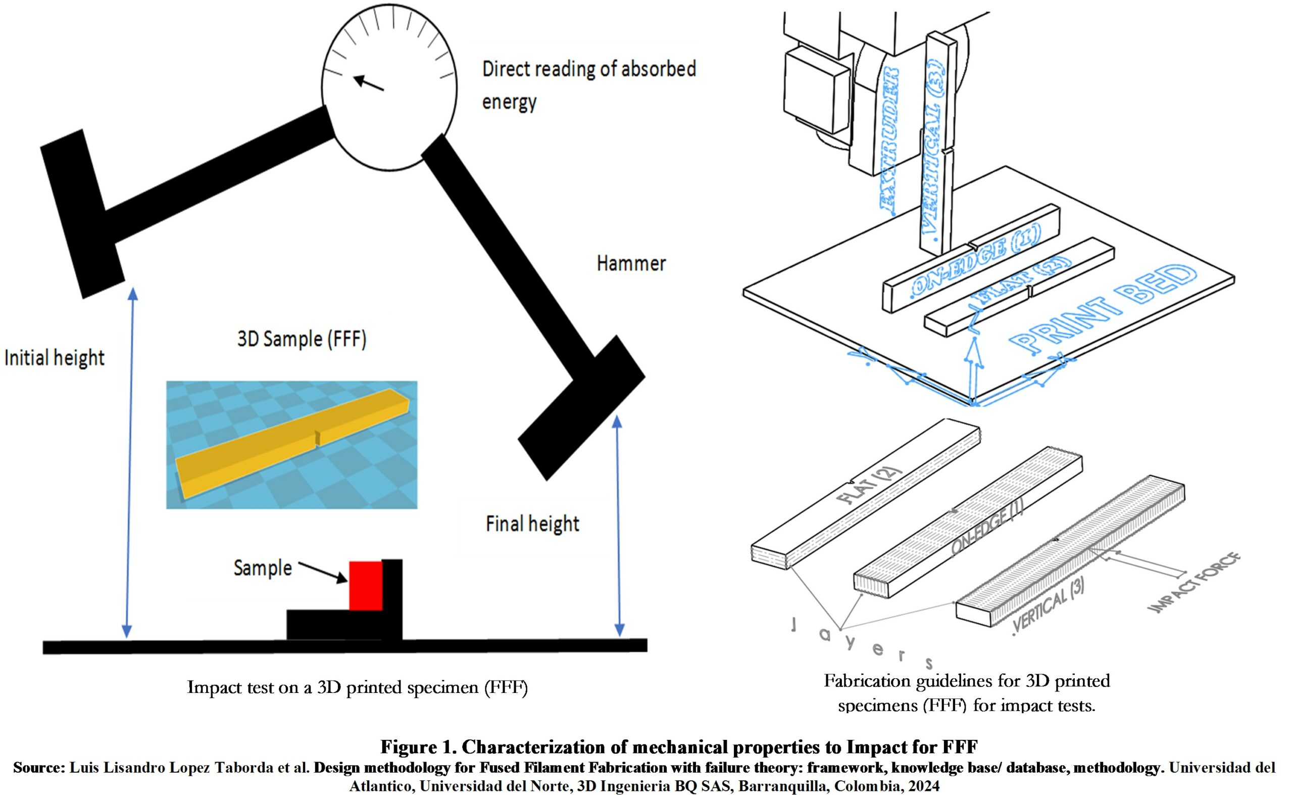
Characterization of mechanical properties to Impact for FFF
The following are the codified guidelines for improving mechanical properties (MEC) based on case analyses:
MEC-01. The percentage of filler must be increased to increase the mechanical strength.
The mechanical resistance increases with the percentage of filler, whether it is resistance to tension, bending, impact, or compression [1]–[4].
MEC-02. For 100% infill density, use +45°/-45° infill orientation for any loading, except creep, where 90° orientation is recommended.
At 100% infill density, infill orientation does not produce significant changes in tensile, flexural, and compressive strength, with sensitivity for impact strength, fatigue strength, and fracture toughness. For sensitive properties, it is recommended to use +45°/-45° infill orientation. For creep (slow creep deformation), a 90° infill orientation is recommended [1]–[4]
MEC-04. For optimal strength, it is recommended to fabricate parts oriented in the following order of highest to lowest strengths: edge, horizontal, and vertical.
The anisotropy of tensile strength, bending, and flexural fatigue is relatively low for edge and horizontal orientations, but very high when comparing edge and horizontal to vertical orientation [1], [5]–[7]
Figure 1-2 summarizes the specimen fabrication and test load orientations, illustrating the above guideline.
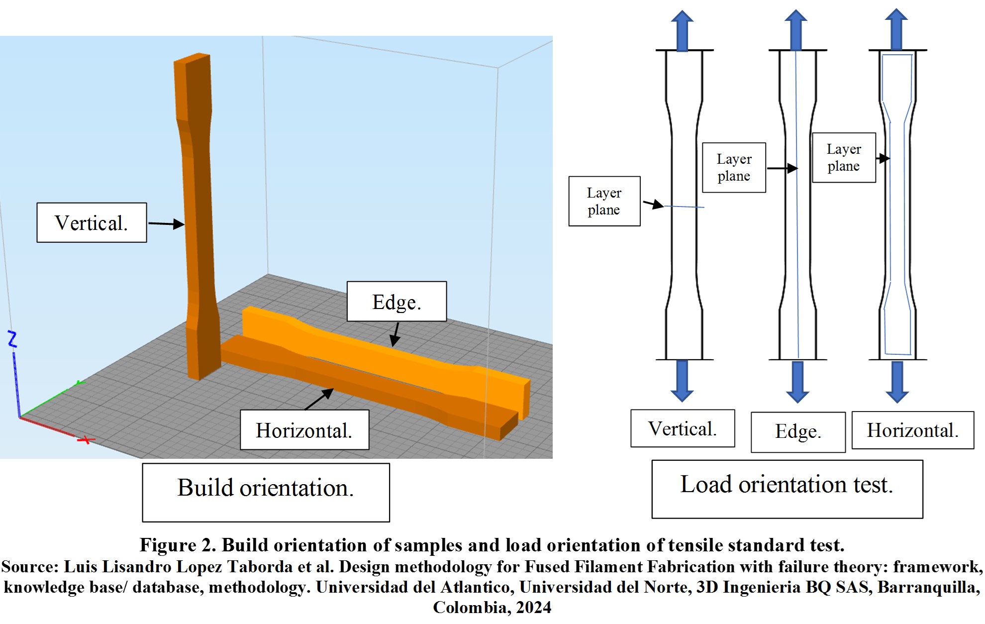
Figure 1-2 illustrates how it is preferable to manufacture the part so that the load is parallel or aligned with the manufacturing layer and not perpendicular to the build plane.
MEC-05. The optimal manufacturing orientations to achieve the highest strengths in fracture toughness, impact strength, and creep vary depending on the type of load and other factors. For example:
- Impact strength depends on the material, and the most favorable orientation may vary [5].
- For fracture toughness, it is advantageous to manufacture in a vertical orientation rather than horizontal, as the crack is oriented perpendicular to the printing plane [8].
- In terms of creep resistance, the edge influenced by perimeter layers is the most resistant, followed by the vertical and horizontal orientations [9], [10].
MEC-06. Before modifying parameters to enhance strength, to take a decision is recommended to characterize the strength of parts to printing speed, extrusion temperature, and layer thickness.
The effect of process parameters on strength varies depending on the material, interrelationships with other parameters, nonlinearities, and factors such as printer, material suppliers, build orientation, and infill orientation. While there is a general tendency to increase temperature, decrease speed, and reduce layer height to improve strength, there may be cases where the opposite is true, depending on the specific circumstances mentioned [6], [11], [12].
MEC-08. For semi-crystalline materials such as PLA, the temperature of the platform should be increased because it increases the impact strength, reduces anisotropy [4].
MEC-11. It is recommended to fabricate only one piece at a time. The fabrication time affects the mechanical properties of the parts; therefore, the number of replicas fabricated affects and reduces the strength of small-area parts (vertical 3D prints) [13].
MEC-12. Choose the type of support based on strength while paying attention to printing times, material waste, accuracy, and roughness to align with the design’s required objectives. The type of support used in cantilever, overhang, or bridge parts affects the accuracy and mechanical strength of the part [14].
MEC-13. The recommendation is to mechanically characterize the materials and the parts built with them [15], [16]. The mechanical properties reported by manufacturers do not correspond to those of mechanical characterizations of scientific articles and are above the scientific values. The properties of a material can vary from supplier to supplier, and mechanical properties vary from industrial to desktop machines for reasons such as the high chamber temperature that desktop printers lack. Mechanical properties may vary depending on the type of specimen used for testing, the size of the nozzle, or the number of perimeter layers.
MEC-14. Please select the color of the PLA carefully, as it can affect the mechanical properties. Color is not significant in mechanical properties except in semi-crystalline materials such as PLA [17].
MEC-15. Consider combining it with other processes to improve mechanical resistance (impact, toughness, flexural, tension, compression) , such as coatings [5], [18], [19], [20] infiltration [21],[22] and thermal treatments [23], [4].
Improvements in Mechanical strength to Impact.
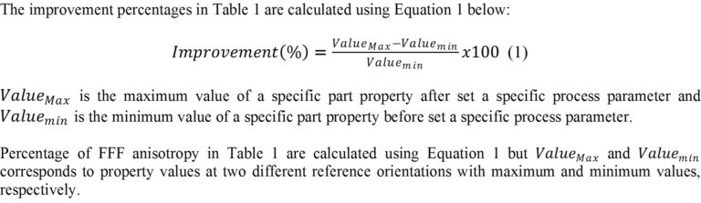
Table 1 summarizes a partial overview of the results obtained after analysis of FFF mechanical property characterizations as a function of process parameters. Table 1 provides ranges of improvement (percentage) or changes, dependent on the interaction of factors.
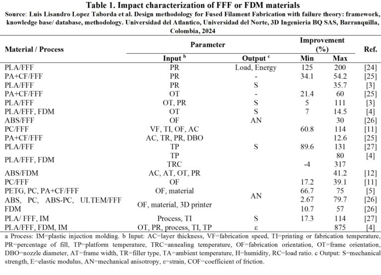
To interpret the findings in Table 1, an example is provided:
- For reference [24], the improvements achieved in PLA FFF Impact characterization range from a minimum of 125% to a maximum of 200%, as indicated below the “Improvement (%)” column. The improvement corresponds to mechanical properties Load, Energy specified below the “Parameter” and “Output” columns. The input parameters that were modified to achieve this improvement is PR, which represent percentage infill; this is specified below the “Parameter” and “Input” columns, along with the table footer indicating the meaning of the table symbols. The specific material and process details are provided in the “Material/process” column. The improvement values are presented as ranges (min and max), because the specific values depend on the interaction of FFF processing factors.
To use the figures of Table 1 or the database of failure theory and mechanical characterizations, from which these figures are derived, when designing a product, proceed as follows:
- Know the product’s properties a priori and compare them with the respective table or base until the material combination, output, and input parameters correspond to the desired property value.
- In case of redesign of parts outside of specifications, verify the percentages of improvement and the combination of material and parameters.
- Quantify times and costs associated with parameters to decide based on properties and costs.
- Consult on the specific base on the specific way to combine the parameters.
- In case of requiring clarification or expansion of specific information, consult the reference.
For more figures on improvements associated with characterization in tension, flexure, impact, compression, fatigue, wear and hardness, creep, and fracture toughness go to the database.
References
[1] R. J. Algarín Roncallo, L. L. Lopez Taborda, and D. Guillen, “Experimental characterization , theoretical modeling and failure analysis of the mechanical behavior of acrylonitrile butadiene styrene parts by fused fi lament fabrication,” no. June, 2023.
[2] N. Elmrabet and P. Siegkas, “Dimensional considerations on the mechanical properties of 3D printed polymer parts,” Polym. Test., vol. 90, p. 106656, 2020.
[3] M. Dawoud, I. Taha, and S. J. Ebeid, “Mechanical behaviour of ABS: An experimental study using FDM and injection moulding techniques,” J. Manuf. Process., vol. 21, pp. 39–45, 2016.
[4] C. Benwood, A. Anstey, J. Andrzejewski, M. Misra, and A. K. Mohanty, “Improving the Impact Strength and Heat Resistance of 3D Printed Models: Structure, Property, and Processing Correlationships during Fused Deposition Modeling (FDM) of Poly (Lactic Acid),” ACS Omega, vol. 3, no. 4, pp. 4400–4411, 2018.
[5] L. L. L. Taborda et al., “Experimental study of resin coating to improve the impact strength of fused filament fabrication process pieces,” Rapid Prototyp. J., vol. ahead-of-p, no. ahead-of-print, Mar. 2021.
[6] J. M. Chacón, M. A. Caminero, E. Garc\’\ia-Plaza, and P. J. Núñez, “Additive manufacturing of {PLA} structures using fused deposition modelling: Effect of process parameters on mechanical properties and~their optimal selection,” Mater. Des., vol. 124, pp. 143–157, Jun. 2017.
[7] J. M. Puigoriol-Forcada, A. Alsina, A. G. Salazar-Mart\’\in, G. Gomez-Gras, and M. A. Pérez, “Flexural fatigue properties of polycarbonate fused-deposition modelling specimens,” Mater. Des., vol. 155, pp. 414–421, Oct. 2018.
[8] M. R. Khosravani, F. Berto, M. R. Ayatollahi, and T. Reinicke, “Fracture behavior of additively manufactured components: A review,” Theor. Appl. Fract. Mech., vol. 109, p. 102763, 2020.
[9] A. G. Salazar-Martín, M. A. Pérez, A.-A. García-Granada, G. Reyes, and J. M. Puigoriol-Forcada, “A study of creep in polycarbonate fused deposition modelling parts,” Mater. Des., vol. 141, pp. 414–425, 2018.
[10] O. A. Mohamed, S. H. Masood, and J. L. Bhowmik, “Experimental investigation of creep deformation of part processed by fused deposition modeling using definitive screening design,” Addit. Manuf., vol. 18, pp. 164–170, 2017.
[11] C. Gutierres, J. Marun, and L. Lopez, “CARACTERIZACIÓN DE PROBETAS FABRICADAS CON POLICARBONATO POR EL MODELADO POR DEPOSICIÓN FUNDIDA (FDM),” UNIVERSIDAD DEL ATLÁNTICO, FACULTAD DE INGENIERA, PROGRAMA DE INGENIERÍA MECÁNICA, Puerto Colombia, Atlantico, Colombia, 2020.
[12] A. K. Sood, R. K. Ohdar, and S. S. Mahapatra, “Parametric appraisal of mechanical property of fused deposition modelling processed parts,” Mater. Des., vol. 31, no. 1, pp. 287–295, 2010.
[13] M. Faes, E. Ferraris, and D. Moens, “Influence of Inter-layer Cooling time on the Quasi-static Properties of {ABS} Components Produced via Fused Deposition Modelling,” Procedia {CIRP}, vol. 42, pp. 748–753, 2016.
[14] J. Jiang, J. Lou, and G. Hu, “Effect of support on printed properties in fused deposition modelling processes,” Virtual Phys. Prototyp., pp. 1–8, 2019.
[15] R. Algarín, J. Vargas, and L. Lopez, “Elementos protésicos de fácil acceso para personas con amputación de miembro inferior.” BARRANQUILLA, COLOMBIA, 2019.
[16] E. CASTRO, DARIO EDEL CASTAÑO and L. LOPEZ, “CARACTERIZACIÓN MECÁNICA DE PROBETAS DE POLIETILENO TEREPHTHALATE CON GLICOL IMPRESAS EN 3D MEDIANTE EL MÉTODO DE MODELADO POR DEPOSICIÓN FUNDIDA,” UNIVERSIDAD DEL ATLÁNTICO, FACULTAD DE INGENIERÍA, PROGRAMA DE INGENIERÍA MECÁNICA, Puerto Colombia, Atlantico, Colombia, 2021.
[17] D. Popescu, A. Zapciu, C. Amza, F. Baciu, and R. Marinescu, “{FDM} process parameters influence over the mechanical properties of polymer specimens: A review,” Polym. Test., vol. 69, pp. 157–166, 2018.
[18] L. H. Hsu, C. T. Lu, G. F. Huang, J. T. Chen, W. C. Chuang, and H. S. Shih, “Introduction to a Type of Resin-Reinforced Rapid Prototyping Transtibial Socket,” in ASME 2010 10th Biennial Conference on Engineering Systems Design and Analysis, 2010, pp. 717–723.
[19] L. H. Hsu, G. F. Huang, C. T. Lu, D. Y. Hong, and S. H. Liu, “The development of a rapid prototyping prosthetic socket coated with a resin layer for transtibial amputees,” Prosthet. Orthot. Int., vol. 34, no. 1, pp. 37–45, 2010.
[20] S. Kannan and D. Senthilkumaran, “Assessment of mechanical properties of Ni-coated abs plastics using FDM process,” IJMME-IJENS, vol. 14, no. 3, pp. 30–35, 2014.
[21] J. F. P. Lovo, I. L. de Camargo, L. A. O. Araujo, and C. A. Fortulan, “Mechanical structural design based on additive manufacturing and internal reinforcement,” Proc. Inst. Mech. Eng. Part C J. Mech. Eng. Sci., vol. 234, no. 2, pp. 417–426, 2020.
[22] K.-H. Jo, Y.-S. Jeong, J.-H. Lee, and S.-H. Lee, “A study of post-processing methods for improving the tightness of a part fabricated by fused deposition modeling,” Int. J. Precis. Eng. Manuf., vol. 17, no. 11, pp. 1541–1546, 2016.
[23] K. R. Hart, R. M. Dunn, and E. D. Wetzel, “Increased fracture toughness of additively manufactured semi-crystalline thermoplastics via thermal annealing,” Polymer (Guildf)., vol. 211, p. 123091, 2020.
[24] A. Tsouknidas, M. Pantazopoulos, I. Katsoulis, D. Fasnakis, S. Maropoulos, and N. Michailidis, “Impact absorption capacity of 3D-printed components fabricated by fused deposition modelling,” Mater. Des., vol. 102, pp. 41–44, 2016.
[25] E. V. de Toro, J. C. Sobrino, A. M. Mart\’\inez, and V. M. Egu\’\ia, “Analysis of the influence of the variables of the Fused Deposition Modeling ({FDM}) process on the mechanical properties of a carbon fiber-reinforced polyamide,” Procedia Manuf., vol. 41, pp. 731–738, 2019.
[26] D. A. Roberson, A. R. T. Perez, C. M. Shemelya, A. Rivera, E. MacDonald, and R. B. Wicker, “Comparison of stress concentrator fabrication for 3D printed polymeric izod impact test specimens,” Addit. Manuf., vol. 7, pp. 1–3, 2015.
[27] L. Wang, W. M. Gramlich, and D. J. Gardner, “Improving the impact strength of Poly (lactic acid)(PLA) in fused layer modeling (FLM),” Polymer (Guildf)., vol. 114, pp. 242–248, 2017.