
DF-FFF with TEFA
Figure 1 below summarizes the classification and description of the Faiilure theory FFF cases that were found during the case analysis of the research:
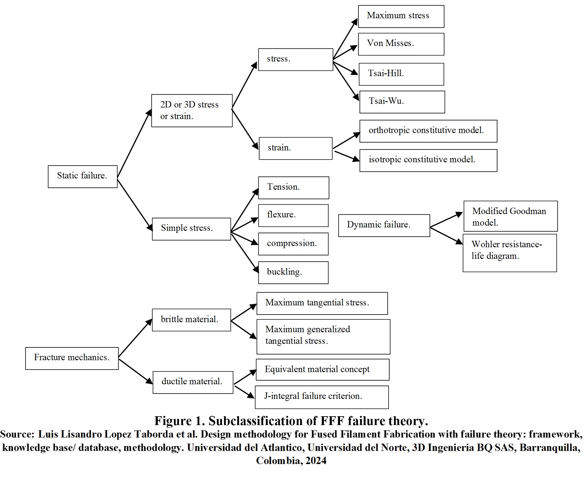
Figure 2 summarizes the four steps for predicting the failure of parts manufactured by FFF.
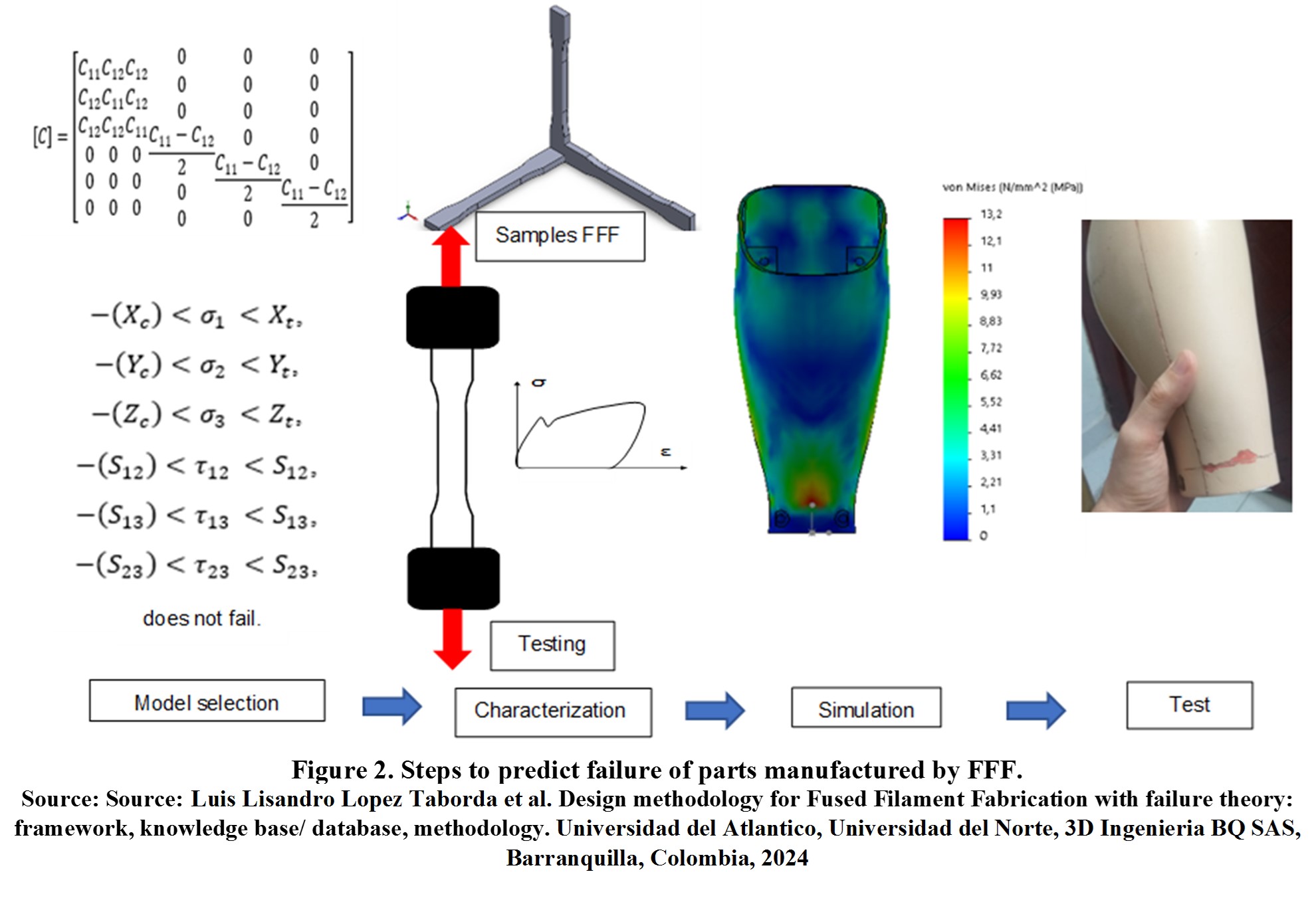
Each step of the above figure is explained below:
- The process of predicting the failure of a part starts from the definition of a specific model corresponding to an actual situation and the nature of the material.
- The model inputs determine the minimum number of tests to characterize the material and feed the model. Try to use a specific standard to characterize the material.
- The part is subjected to an actual load state using finite element simulation. The state of stresses that feed the predictive failure model is obtained, determining its failure, or overcoming the load without failure.
- The part is manufactured and subjected to an actual load to corroborate the failure criterion and reliability.
The uncertainty of the different models will depend on the materials, manufacturing parameters, models used, type and magnitude of load, and geometry. In general, the failure theory database provides a variety of models and associated uncertainties.
It should include using failure theories to quantify safety factors in cases where parts are subjected to high mechanical performance.
Next Figure 3 summarizes the general DF-FFF methodology with TEFA grouped by the different phases of the design process.
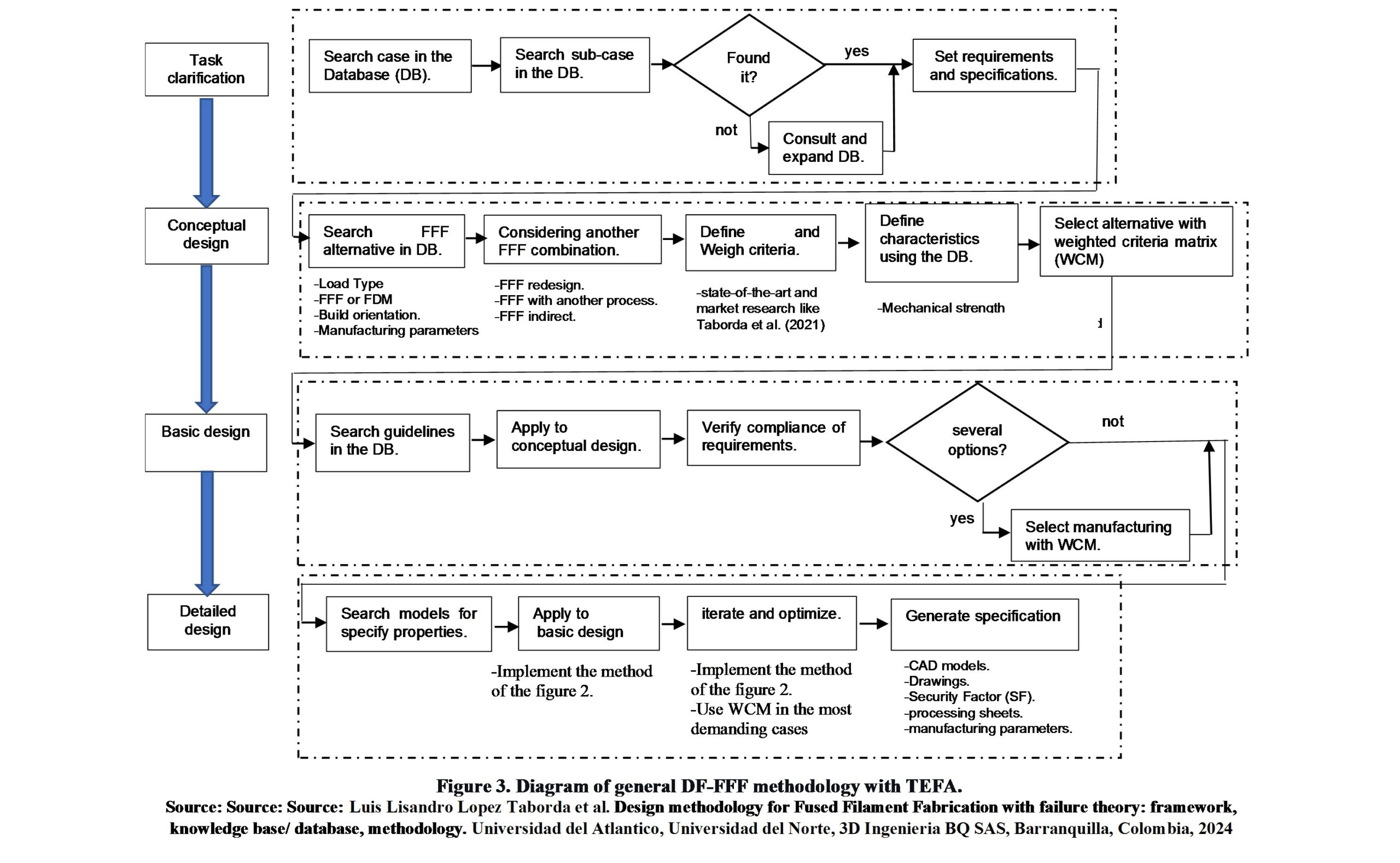
The following explains the steps in Figure 3 grouped by each design phase.
Task clarification (TC). At the end of this phase, the lists of requirements, criteria, or specifications/properties of the product to be developed will be obtained. For this purpose, the following steps must be followed:
a) Search within the database (DB) for the general case to which the product to be designed belongs according to one of the cases described in Figure 1.
b) Within the general case, the specific case is searched according to the products described in Figure 1.
c) If the specific or similar product is not found in the DB, it is possible to:
- Search in the specialized bibliography.
- Analyze the references that coincide with the product.
- Define the product requirements and specifications for each reference according to Figure 1.
- Feedback of the DB.
d) Once a DB case matching the desired product is found, the list of requirements is displayed with the specifications defined for the DB case, and based on these, the product is defined for its own product.
Conceptual Design (CD). At the end of this phase, several initial CD will be obtained, and the selection of one or more will be based on requirements or criteria. For this purpose, the following steps should be followed:
a) Search for a combination of materials and specific FFF process parameters to meet the initial specifications. Considering:
- Load Type
- FFF and FDM materials/3D printers.
- Build orientation.
- Manufacturing parameters: speed, temperature, layer height, perimeter layer, infill density, infill angle, infill type.
b) If a feasible FFF alternatives is found or not, considering:
- a FFF redesign strategy
- a combination of FFF materials and processes with conventional materials and processes
- an indirect FFF manufacturing method
Look for correspondence between the requirements and specifications of the alternatives to ensure compliance with requirements.
c)Define selection criteria based on the requirements and specifications set in the CT phase.
d)Assign a weighting to the criteria obtained in this phase based on the objectives pursued, market statistics, and quantitative figures.
- For example, state-of-the-art and market research like Lopez et al. (2021).
e) Establish quantitative characteristics of the alternative per criterion using the DB. Considering:
- Mechanical strength
- Security factor (SF) according to theory failure.
f) Evaluate and select the alternative using the weighted criteria matrix (WCM) method.
Basic Design (BD). At the end of this phase, the BD of the product will be obtained, that is, the rules and process to modify the DC, the modified DC to a shape close to the final shape, and the specific manufacturing process to be used. To this end, the following steps must be followed:
a) Search for the most suitable design rules.
- Considering: DB of the present work to improve the mechanical strength of the pieces.
b) Analyze and study the rules or methods by consulting the original references (framework) and apply them to the CD to transform the concept to a basic form according to the requirements.
c)Verify the level of concordance between the primary forms and the requirements.
- Use the DB for example DB and the specialized bibliography to quantify properties and percentage of improvement and features as support.
d)If different basic processing and design forms were generated accordingly, based on properties and requirements, a WCM evaluation would be required to select the BD and its processing form.
Design in Detail (DD). At the end of this phase, the final digital model and the specifications and process parameters will be obtained. For this purpose, the following steps must be followed:
a) In the DB and specialized bibliography, search for the information, model, or program that helps to specify the product property.
b) Appropriate in the use of models or CAD (Computer Aided Design) /CAM (Computer Aided Manufacturing) programs to apply to DB and transform it into DD.
- Considering implement the method of the figure
c)Use the data and models to simulate and modify the design performance until it conforms to the requirements through an iterative process.
- Considering implement the method of the figure 2.
- Use WCM in the most demanding cases.
d)Generate design specifications by exporting:
- CAD models.
- Drawings
- Security Factor (SF).
- processing sheets.
- manufacturing parameters.
On the other hand, in case of redesigning parts manufactured with FFF, whose properties do not conform to the desired specifications, the steps in Figure 4 should be followed
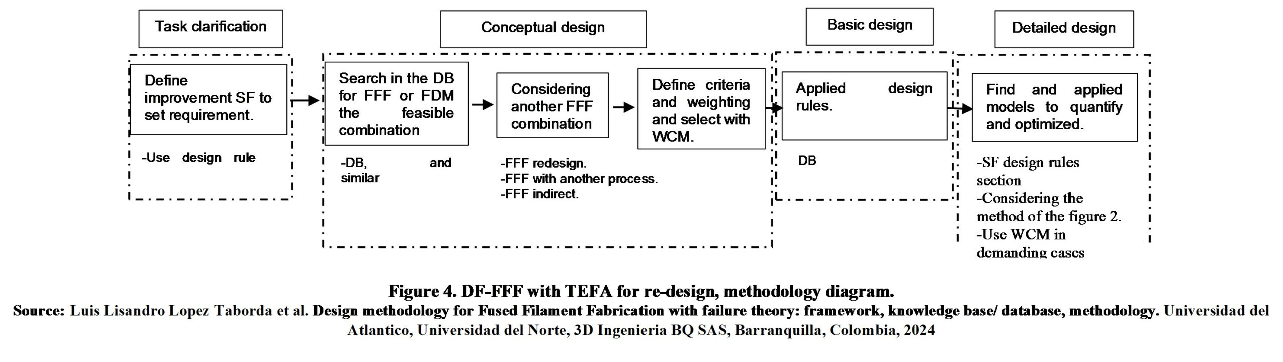
The following explains the steps in Figure 4:
a) Use security factor according to theory failure to define the percentage degree of improvement required for the part to conform to requirements.
- Use design rule of section of the present work.
b) Search in the DB to find feasible material and printing condition to set requirements.
- Consulting DB and similar, the percentages of improvement possible with FFF or FDM.
c)If a feasible FFF alternatives is found or not, considering:
- a FFF redesign strategy
- a combination of FFF materials and processes with conventional materials and processes
- an indirect FFF manufacturing method
d)Define selection criteria and weighting and Select alternative with weighted criteria matrix (WCM).
e) To consult the specific way the processes and their parameters for FFF or FDM.
- Consult rules of section of the present work
f) Find and applied models to quantify and optimized part.
- Security factor according to theory failure.
- Considering implement the method of the figure 2.
- Use WCM in the most demanding cases.
References
[1] L. L. Lopez Taborda, H. Maury, and J. Pacheco, “Design for additive manufacturing: a comprehensive review of the tendencies and limitations of methodologies,” Rapid Prototyp. J., vol. 27, no. 5, pp. 918–966, Jun. 2021.
[2] Luis Lisandro Lopez Taborda et al. Design methodology for Fused Filament Fabrication with failure theory: framework, knowledge base/ database, methodology. Universidad del Atlantico, Universidad del Norte, 3D Ingenieria BQ SAS, Barranquilla, Colombia, 2024