
Database for Process Chain with FFF
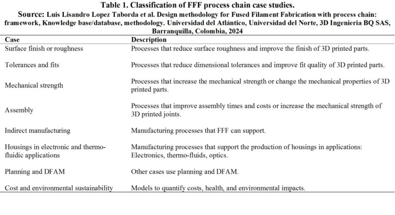
Table 1 summarizes the classification and description of the FFF process chain cases that were found during the case analysis of the research
Figure 1 summarizes the FFF process chain case subclassifications obtained from the previous table and during the analysis of cases. Figure 1 excludes the cost and sustainability case as it applies to all other cases. Housing cases are omitted as they encompass the same processes as indirect manufacturing and assembly. While not explicitly stated, each case includes planning and DFAM, which involves manufacturing and design planning based on design rules, theoretical-numerical methods, or experimental characterizations.
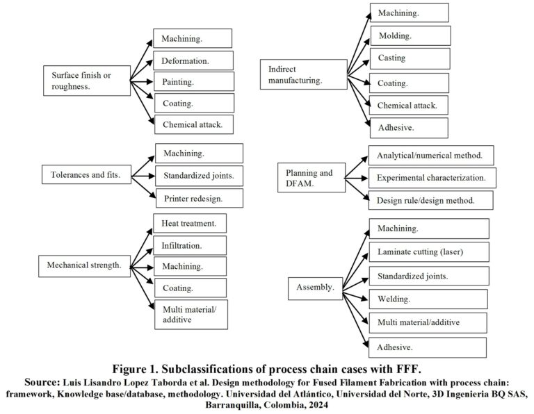
Figure 2 summarizes the main headings of the database.
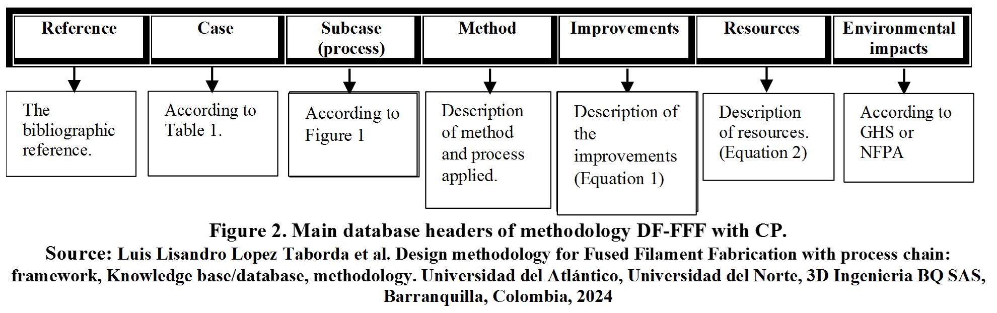
Below is a detailed explanation of each heading in Figure 2.
- Reference: Contains the bibliographic reference analyzed to generate specific and general guidelines.
- Case:One (1) of the eight (8) cases in Table 1 in which the analyzed reference can be classified.
- Subcase:Some of the specific process or sub-cases in Figure 1, depending on the case to which the reference belongs.
- Method: Description step-by-step for combining conventional manufacturing processes with FFF.
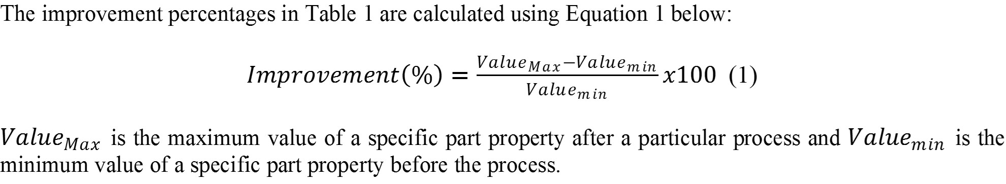
- Improvements: It is a percentage improvement obtained in the property of an FFF part by combining it with a conventional manufacturing process.
- Resources: Describes additional materials and conventional machinery needed for combining FFF with conventional manufacturing, including associated time, costs, and licenses
The service costs include machinery depreciation, energy consumption, depreciation of computers and software licenses with their energy consumption and internet service, and skilled labor.
- Environmental Impacts: Describes health and environmental hazards of extra materials based on GHS and NFPA scales, incorporating measures for prevention and management as per material safety data sheets.
Under each heading or column is the respective information, and each row contains information related to a specific case or reference. The purpose is to search according to the desired case to apply the guidelines of other cases to one’s case. In case of detailed information, the reference can be consulted directly.
Process Chain
| Group | Requirement | Secondary process | References | Objective | Method | Results and conclusions | printer, machines | brand | material | characterization | parameters | parameter values | Observation and suggestions | Additional resources required (materials, software, costs and time) |
|---|---|---|---|---|---|---|---|---|---|---|---|---|---|---|
| G1 | Finished or surface roughness, tolerances and fits, mechanical strength | Experimental characterization, analytical computer tool | S11 | The purpose of this document is to examine the various preprocessing and postprocessing approaches used to enhance the surface characteristics of acrylonitrile butadiene styrene (ABS) prototypes based on the fused deposition modeling (FDM) method. | The consequences and scope of the pre-processing and post-processing parameters of FDM have been studied independently. The comprehensive study includes the domain, limitations, validity, and scope of various techniques adopted to improve the surface characteristics of ABS parts. Replicas of hip implants are manufactured by maintaining the reviewed optimal pre-processing parameters, and a case study has been conducted to evaluate the capability of the steam smoothing process to enhance surface finish. | Process parameter optimization: * Manufacturing orientation, manufacturing with a 0° angle (horizontal) produces the maximum surface performance. In most studies, orientation angles of 0° (horizontal) and 90° (vertical) were considered more effective for surface finishing, cost, and manufacturing time. Construction angles between 40° and 60° reduced surface finishing and increased cost, as maximum support material was used due to the model's inclination. Some authors observed that a 30° orientation angle is the most effective for surface finishing and mechanical properties, such as flexural and impact strength, using Grey Taguchi optimization techniques. The horizontal surface has better surface finishing than the vertical surface and worse for circular shapes due to the formation of elliptical curves on the descending surface of the layer junction. Most experimental characterizations and optimizations employ standard square and rectangular models by orienting them at different angles. The problem arises when real parts with intricate shapes and intricate details need to be manufactured. * Decreasing the nozzle diameter and layer height reduces the staircase effect defect but increases construction times and cost. There is a minimum layer thickness beyond which it cannot be decreased, subject to the printer's minimum resolution and nozzle diameter. * The minimum width of the road resulted in maximum surface finishing and dimensional accuracy. It has been noted that narrower widths of roads also improved the mechanical properties of FDM parts. * Wider contour (perimeter) width is better for surface finishing and dimensional accuracy, as thin contours are easily deformed by the heat generated during extrusion. * Surface finishing generally increases with negative and positive air gaps, while minimum surface finishing and dimensional accuracy occur with zero air gaps. * The best surface finishing was obtained with a 0° frame angle and the worst with 60°, while the frame angle of 45° was optimized for the best surface finishing and 0° for the best dimensional accuracy using an optimization algorithm. Others concluded that the 45°/45 frame angle style provides the maximum surface finishing. Additionally, a 30° frame angle provides maximum flexural and impact strength. The variation in interpretations by different authors may be due to differences in CAD models and other parameters. * Higher temperature produces a smooth surface due to delayed solidification. The model temperature is the third most important factor affecting the surface after layer thickness and orientation angle. Below 80°C, there was less plastic adhesion to the build plate, while dimensional accuracy decreased above 100°C. Higher temperature leads to good surface finishing but poor dimensional accuracy. Slicing: * Adaptive slicing, the maximum cusp height limit is specified by the user, and therefore the algorithm automatically slices the CAD within a given range. This method imposes constraints on surface roughness and cusp height uniformly across the entire surface of the part. Adaptive slicing is based on the region where the user can vary surface roughness in different places on the part's surface according to their needs. There are few limitations in the techniques mentioned above, such as complexities and errors in tessellated CAD files. * Direct slicing, the slicing software directly slices the CAD without conversion to .stl, which is accurate, fast, and requires less storage memory. However, there is a difficulty as the CAD model is stored as mathematical definitions and analytical surface instead of points and coordinates, requiring software and hardware development to implement curved layer slicing algorithms with the aim of improving both mechanical properties and surface finishing of FDM parts. Additionally, surface finishing can only be improved to a certain level, depending on the hardware and software, which is unacceptable for using FDM parts for precision rapid machining. | FFF, FDM, process parameter optimization, slicing optimization | - | ABS | Roughness Ra, dimensional deviation or dimensional tolerance, mechanical resistance. | Optimization of process parameters: Print orientation (OI), nozzle diameter (d), layer height (t), layer width or pattern (w), airgap or % (AG), pattern orientation (OT), print temperature (TI), bed temperature (TC); slicing optimization: adaptive slicing (variation of cutting by zone), direct cutting (direct slicing without stl conversion). | Optimization process parameters: OI: 0, 30, 60, 90°; airgap or % (AG or %: +, -, 0.0mm), OT: 0, 30, 60, 45, 90, TC: 80, 100; | Increase print temperature, keep bed temperature between 80 to 100°C. Orient the piece at 0° (horizontal) and 90° (vertical) except for curved surfaces. Avoid orientations that generate support. Use a 0° or 45° pattern orientation. Use 100% infill percentages or 0.0mm airgap. Minimize layer height, nozzle diameter, and line width to improve finish but at the expense of manufacturing times and costs. Increase line width on the contour or perimeter. Use slicing programs that include adaptive cutting and discretize layer height by piece zone as needed. | adaptive slicing program: *Simplify 3D at $149 USD permanent license (https://www.simplify3d.com/software/release-notes/version-4-1-0/ consulted on March 29, 2021), *Slic3r at $0 USD (https://slic3r.org/ consulted on 29/03/2021), *CURA Ultimaker at $0 USD free version, $300 USD light license per year, $720 USD standard license per year, $3600 USD advanced license per year (https://ultimaker.com/en/software/ultimaker-cura consulted on 29/03/2021), *IdeaMaker Raise 3D at $0 USD (https://www.raise3d.com/ideamaker/ consulted on 29/03/2021) |
| G1 | Finished or surface roughness, tolerances and fits, mechanical strength | Machining, Deformation | S11 | The purpose of this document is to examine the various preprocessing and postprocessing approaches used to enhance the surface characteristics of acrylonitrile butadiene styrene (ABS) prototypes based on the fused deposition modeling (FDM) method. | The consequences and scope of pre-processing and post-processing parameters of FDM have been studied independently. The comprehensive study includes the domain, limitations, validity, and scope of various techniques adopted to improve the surface characteristics of ABS parts. | Mechanical finishing: *Manual sanding, Being simple and economical, manual methods are not controlled, measured, consistent, and precise, and depend on the operator. *Abrasive grinding, it used the abrasive machining action of sandpapers of different grain sizes rotating on a wheel as a material removal process by chip formation. Faster feed rate and smaller media increased the material removal rate and improved surface hardness, implemented abrasive grinding using bulk laminar abrasive paper to achieve a 90% improvement in surface finish with very little deviation in dimensions. *Abrasive flow machining, a high-speed abrasive jet impacts the rough surface until it is smoothed, the pressure of the media, grain size, and flow time control the surface roughness, with a 70% improvement in surface roughness of plastic parts using dry air as the carrier and glass beads as the abrasive media. Uneven material removal is a disadvantage, which caused weight loss and a reduction of up to 5.85% in thickness, the process was very random and aggressive as it damaged edges and corners. *Sandblasting, improvements of up to 96% in surface roughness. Sandblasting has been recommended by Stratasys for post-vapor smoothing and has proven to be an ultra-fine finishing process. *Vibratory bowl finishing, abrasives mixed with water through a vibratory mass spring system, different material removal rates are achieved depending on time, size, shape, weight, and compound of the media, with an increase of 31.67% and 4.59% in surface roughness and hardness, respectively, using a pyramidal-shaped media with longer machining times from 3h to 4h, it was found that machining for more hours and using a lower media weight provided better dimensional stability for ABS parts. *Barrel tumbling, parts are loaded into a closed rotating tube with an abrasive compound and water. The process requires low initial, operating, and maintenance costs and is capable of machining different geometries without using any fixtures, ceramic media of different geometries were used and a 52% decrease in surface roughness was reported with triangular media. Rotation speed, machining time, and shape and size of the media were found to be the main parameters controlling the material removal rate, they recognize that the orientation angle of FDM parts and the barrel finishing time are the most important parameters in the case of surface roughness and dimensional accuracy. The maximum material removal rate occurs at a 90° angle orientation while the minimum at 18°. *Hot cutting machining, the hybrid system has been proposed by integrating hot cutting with additive technique, the lay angle and cutting direction were the main influential parameters. *Ball polishing to press the surface peaks into the valleys, increased penetration depth and spindle speed improved surface finish and wear of ABS parts, while hardness increases with the force applied by the burnishing tool. *Mechanical methods present challenges with complex and intricate shapes. *The abrasive action of the media rounds sharp edges and corners and distorts the geometry and dimensional stability of the part. *Deeper surfaces within grooves, notches, or other recesses are more difficult to reach by abrasives. *They are quite inconsistent in imparting a uniform surface finish on all parts. | FFF, FDM, manual sanding, abrasive grinding or grinding, abrasive flow machining, sandblasting, vibratory bowl or tumbler, barrel deburring, ball polishing, hot machining | - | ABS | Roughness Ra, dimensional deviation or dimensional tolerance, hardness (ball finish) | Manual sanding; abrasive grinding or sanding (use of different sandpaper and a wheel); abrasive flow machining (pressure of the medium (dry air), grain size (glass beads), flow time); sandblasting; vibratory bowl (abrasives mixed with water, type of abrasive media (pyramidal), vibration time (3 to 4 hours)); hot machining; ball polishing (spindle speed, penetration depth, applied force); | Grinding or sanding (use of different sandpaper and a wheel); abrasive flow machining (dry air pressure, glass bead grain size, blasting time); vibratory bowl (abrasives mixed with water, type of abrasive media for example pyramid, vibration time of 3 to 4 hours); | *Manual sanding, Being simple and economical, manual methods are not controlled, measured, consistent, and precise. *Abrasive finishing techniques on plastic parts using sandblasting, barrel tumbling, centrifugal tumbling, vibratory bowl, and ultrasonic abrasion achieve an average improvement of 40%, 78%, 81%, 73%, and 60%, respectively, in surface finishing. *Abrasive finishing resulted in the removal of unwanted material from edges and corners due to the impact of abrasive media in these mass finishing processes. *Implemented abrasive grinding or sanding using bulk laminar abrasive paper to achieve a 90% improvement in surface finishing with very little deviation in dimensions. *Abrasive blasting, 70% improvement in surface roughness of plastic parts using dry air as a carrier and glass beads as abrasive media. It caused weight loss and a reduction of up to 5.85% in thickness, the process was very random and aggressive as it damaged edges and corners. *Sandblasting, improvements of up to 96% in surface roughness. *Finishing of vibratory bowl or vessel, with an increase of 31.67% and 4.59% in surface roughness and hardness, respectively, using a pyramid-shaped media with longer machining times from 3h to 4h. *Tumbling or barrel finishing, presents a 52% decrease in surface roughness with triangular media. The maximum material removal rate occurs at the 90° angle orientation while the minimum at 18°. *Mechanical methods present several challenges to complete complex and intricate shapes. The abrasive action of the media rounds sharp edges and corners and distorts the geometry and dimensional stability of the piece. Additionally, deeper surfaces within grooves, notches, or other indentations are harder to reach by abrasives. *Mass finishing methods are effective but are quite inconsistent in imparting a uniform surface finish on all parts. | *Lijado manual: sandpaper $3.17usd for 6 sandpapers of 93x228mm, number (grain size) 150-100-60 *Sand Blasting: Sandblasting gun or blasting from $22usd to $49.45 usd, 90-150 PSI compressor with a minimum of 4.0 CFM (recommendations according to sandblasting gun), 2 1/2 to 3 1/2 HP, from $170usd to $360usd, hose and couplings for compressor at $50 USD, sand for sandblasting at $10 USD for 25kg *Abrasive Jet Machining: Sandblasting gun or blasting from $22usd to $49.45 usd, 90-150 PSI compressor with a minimum of 4.0 CFM (recommendations according to glass bead supplier 20-60 PSI maximum at 70 PSI), 2 1/2 to 3 1/2 HP with a minimum of 4.0 CFM, from $170usd to $360usd (silent and oil-free, consulted on Amazon USA on 29/03/2021), hose and couplings for compressor at $50 USD, glass beads for blasting at $10 USD for 8lb, grain or mesh 100-170 *Abrasive Grinding or Grinding: 1/2 HP bench grinder with 6' diameter at $44.4 usd or 130Watt rotortool with kit including abrasive stone and sandpaper at $43 usd or 4x36 belt sander and 6 diameter disc with 1/2 HP at $255.4usd, 4x24 belt sandpaper grain 120 or 240 and 3 units at $4.2USD or sanding disc at $3.87USD. *Vibratory Tumbler: 0.05 cubic feet vibratory tumbler, 60hz, 115V at $100usd or 0.18 cubic feet vibratory tumbler, 304.8mm diameter x 106.7mm high, 60hz, 115V at $500usd, complete kit of medium rock for polishing with 4 different steps of 3.5 pounds at $38USD. *Barrel Tumbling or Boring: Rotary drum with a capacity of 3.3 liters (317.5mm length x 241.3mm diameter, approximate measurements), at $112USD, Rotary drum with a capacity of 7 liters (381mm length x 279.4mm diameter, approximate measurements) at $190USD, 5 lb bag of abrasive media of stainless steel cylinders with a diameter of 1.2mm x 6.47mm long at $42.95USD. *Hot Machining: CNC milling/engraving machine at $290-370USD, set of 10 1/4 carbide bits at $47USD, soldering iron at $20USD *Honing: CNC milling/engraving machine at $290-370USD, honing tool $40 usd (estimated based on cylinder honing) *Machines require energy resources and consumables for their operation. *Some operations require the use of ventilation and personal protective equipment that increase costs (prices consulted on Amazon USA and Mercado Libre Colombia from March to April 2021) |
| G1 | Finished or surface roughness, tolerances and fits, mechanical strength | coating, chemical attack | S11 | The purpose of this document is to examine the various preprocessing and postprocessing approaches used to enhance the surface characteristics of acrylonitrile butadiene styrene (ABS) prototypes based on the fused deposition modeling (FDM) method. | The consequences and scope of pre-processing and post-processing parameters of FDM have been studied independently. The comprehensive study includes the domain, limitations, validity, and scope of various techniques adopted to improve the surface characteristics of ABS parts. | Chemical finish: *Manual painting, saves time and costs, but manual methods are not uniform. *Acetone immersion, FDM parts are immersed in a solution of acetone (90% dimethyl ketone and 10% water) for a certain time. *Immersion of parts in an acetone solution for 5 minutes also improved flexural strength, tightness, and wear resistance, slightly reduced tensile strength, increased weight, ductility, and compressive strength, while a 1% shrinkage was recorded, concentration-temperature interaction and concentration-time interaction have the greatest impact on surface roughness. *It has been used for the surface finishing of ABS parts for biomedical device applications, the optimal conditions were exposure of 1 to 8 hours with a 60% aqueous solution to obtain the best surface finish (nanoscale) and preserve the characteristics of the parts. *It has been used for sealing and supporting liquid pressures of 276 kPA. *A fan has been used for forced circulation of acetone vapors in a closed chamber, improving the finish by increasing fan revolutions, while longer exposure is required for finishing ABS parts with larger surface area. *Cold vapors at 20°C have been used in a closed container to control rapid vapor-plastic interaction, improving the surface with minimal changes in dimensions up to a 40-minute exposure. However, with a longer duration of 90 minutes, corners and sharp edges are rounded. *Post-processing with acetone has been shown to be a highly effective, easy, fast, and economical surface finishing process, but there is a risk of eroding and dissolving small features of the parts over longer periods and using undiluted acetone, while using a diluted solution can prolong immersion time. Therefore, the method needs to be controlled, automated, and mechanized to carry out more precise and systematic finishing. *Smoothing with vapor, a technique has been developed in which the surface of the part is temporarily arched due to exposure to vapors produced by heating the chemical substance in a controlled environment. Initially, the parts are allowed to cool for a few minutes in the drying chamber and then placed in the smoothing chamber for 10 to 30 seconds. A fixed amount of solvent is heated in the smoothing chamber, and thus the vapors (chemicals) rise to deposit on the hanging ABS part through the surface and temporarily flatten it due to surface tension. After three cycles of vapor exposure, the parts were subjected to a sodium bicarbonate jet. Initial and final readings showed insignificant changes in dimensions with an extremely smooth surface. *Electroplating, wind tunnel models were manufactured using FDM to reduce cost and manufacturing times. Models used without surface finishing do not produce satisfactory results because a highly smooth surface is necessary for high-speed testing. Therefore, FDM parts are etched to clean the surface and then coated with palladium acting as an adhesive agent, finally, chromium is deposited providing the required durability. The thin layer of electroplated chromium on the FDM model improved surface finish, wear resistance, and mechanical strength. Aerodynamic test results showed that the chromium-coated model had good lift capacity compared to the uncoated model. In addition, the data showed very good agreement between the steel model and the coated FDM model within the Mach number range of 0.1 to 0.3. *Improvement in hardness, corrosion resistance, and tensile strength of copper-coated ABS plastics has also been reported. *Electrodeposition of FDM parts improved surface finish and tensile strength of parts with an increase in layer thickness. *Copper, nickel, and chromium coatings have been tested on ABS parts, which tend to increase impact strength and hardness in addition to improving surface finish with increasing coating layer thickness. *The major limitation of coating and electroplating is the added cost of the process and the limited field of applications. The method induces mechanical strength and hardness, but the dimensions of the parts are also altered due to the outer surface layer. *Metal coatings on ABS replicas can increase practical complications during coating castings for rapid tooling applications. *The application of reinforcing fluids such as water-based Epsom salt, wax, acrylic resin protektine, cyanoacrylate, etc., has the potential to reduce surface roughness and improve the mechanical properties of the parts. Increased tensile, compression, and flexural strength of 3D printed parts have been reported with exposure to polyurethane glue, cyanoacrylate, and Epsom salt. *Environmental conditions and construction orientation in plastic parts influence the effectiveness of reinforcements. | FFF, FDM, manual painting, acetone immersion | - | ABS | Roughness Ra, dimensional deviation or dimensional tolerance, mechanical resistance (immersion in acetone) | Manual painting; acetone immersion (acetone/water volume ratio, exposure time, forced convection, vapor or liquid temperature), steam smoothing (fixed liquid amount, temperature, cooling time, exposure time, number of cycles), electrodeposition (fixative type, coating element type, layer thickness). | Immersion of acetone (volumetric percentage: 60%, 90%, exposure time: from 1 to 8 hours, 5 minutes, 40 to 90 minutes), steam smoothing (cooling time: minutes, exposure time: 10 to 30 s; number of cycles: 3), electrodeposition (element: Cu, Ni, Cr, fixing element: palladium). | *Manual painting saves time and costs, but manual methods are not uniform. *Acetone immersion, in addition to improving surface finish, improved flexural strength, tightness (supports fluid pressure up to 246KPa), and wear resistance, slightly reduced tensile strength, increased weight, ductility, and compressive strength, while a 1% shrinkage was recorded. *In acetone immersion, concentration-temperature interaction and concentration-time interaction have the greatest impact on surface roughness. For example, for a 90% acetone solution, 10% dimethyl ketone, and 10% water, the optimal immersion time is 5 minutes. For another case, the optimal conditions were exposure of 1 to 8 hours with a 60% aqueous solution for a good finish without dimensional changes. A fan has been used for forced circulation of acetone vapors in a closed chamber, improving finish by increasing fan revolutions. Cold vapors at 20°C in a closed container have been used to control rapid vapor-plastic interaction, improving the surface with minimal dimensional changes up to a 40-minute exposure. Beyond 90 minutes, sharp corners and edges are rounded. *Post-processing with acetone has proven to be a highly effective, easy, fast, and economical surface finishing process, but there is a risk of eroding and dissolving small features of the parts over longer periods and using undiluted acetone. The use of a diluted solution can prolong immersion time, so the method needs to be controlled, automated, and mechanized to achieve a more precise and systematic finish. *Smoothing with vapor involves cooling the parts for a few minutes in the drying chamber and then placing them in the smoothing chamber for 10 to 30 seconds. A fixed amount of solvent is heated in the smoothing chamber, and the vapors (chemicals) rise to deposit on the ABS part hanging inside, penetrating through the surface and temporarily flattening it. After three exposure cycles, it is subjected to a sodium bicarbonate jet, improving the finish without significant dimensional changes. *Electrodeposition or electroplating (copper and/or nickel and/or chromium coating and fixation with palladium) increases wear resistance, mechanical strength, impact resistance, and hardness, in addition to improving surface finish with increased coating layer thickness, but the dimensions of the parts are also altered due to the coating on the outer surface. *The main limitation of coating and electroplating is the added cost of the process and the limited field of applications. *The application of reinforcing fluids such as water-based Epsom salt, wax, acrylic resin protektine, cyanoacrylate, etc., has the potential to reduce surface roughness and improve the mechanical properties of the parts. Environmental conditions and construction orientation in the mechanical properties of plastic parts influence the effectiveness of reinforcements. | *Manual painting: Spray paint (synthetic enamel) 400ml with coverage of 1.1m^2 in 2 coats and drying time of 20min at $2-3 USD, Polyurethane spray paint 400ml with coverage of 1.1m^2 and fast drying at $8-10 USD, Polyurethane paint 4000ml (4L) with coverage of 18m^2/L, with catalyst (ratio 4:1), and 6-hour pot life at $74-80 USD, Acrylic paint 250ml at $2-3 USD, Airbrush kit (1/6 HP compressor, hose, 22cm^3 container, nozzle, and gun) at $160-170 USD, Brush $1-3 USD. *Acetone immersion: Pure anhydrous acetone x 250ml at $8-10 USD, Pure acetone (nail polish remover) x 473ml at $10 USD. *Electrodeposition: Palladium adhesive element 28.4ml at $2656 USD (https://www.macrotrends.net/2542/palladium-prices-historical-chart-data consulted from March to April 2021), 10-gauge Copper wire x 7.6m at $18 USD, 26-gauge Copper wire x 30m at $8 USD, Copper sheet 152.4x152.4x1.016mm at $15 USD, Nickel strip 0.15x6x50mm x 50 units at $6 USD, Nickel strip roll 0.2x8mmx9.75m at $17 USD, Tin wire roll (99Sn-Ag0.3-Cu0.7) 1mm x 100g at $12 USD, Chromium grains x 1kg at $48 USD, pure chromium order from 1 to 999kg at $29 USD/kg, pure chromium order over 1000kg at $16 USD/kg (https://spanish.alibaba.com/product-detail/hrcr-good-price-pure-chrome-cr-metal-chromium-lumps-62019389951.html?spm=a2700.7724857.normal_offer.d_title.5c5e6214h12fCd&s=p), pure Silver grains 28.4ml at $45 USD, pure Silver ingot Lego piece type, 28.4ml at $50.2 USD, pure Silver ingot coin 2.8x5x0.3cm at $12 USD, 50cm cable with alligator clips, 20AWG at 8A x 10 units at $25 USD or 50cm cable with alligator clips, 22AWG x 5 units at $7 USD, Water or Distilled water, adjustable power supply 110/120V input to 0-30V output/0-10A at $70 USD or power supply 120V input to 0-15V output/0-2A at $45-50 USD, Hydrochloric acid or muriatic acid 1.5L at $1.8-2.0 USD (https://www.unionferretera.com/productos-limpieza-online/productos-quimicos-limpieza/aguafuerte-salfuman-15-litros.html), 250ml beaker flask $5-8 USD, 1000ml beaker flask at $14 USD, set of glass precipitate beakers 50, 100, and 250ml at $11 USD, set of beaker flasks 100, 250, 500, 1000ml at $20-30 USD. *Reinforcement fluid: Epsom salt x 8.618kg at $27 USD, Epsom salt 454g at $2-3 USD, Polyurethane sealer x 300ml at $6.57 USD, Polyurethane glue x 750ml at $3-4 USD, Waterproof polyurethane glue x 1000ml at $33 USD, Cyanoacrylate glue (super glue, loctite 681925) x 2ml x 6 units at $23 USD, Cyanoacrylate glue (super glue, loctite 1699233) x 4g x 6 units at $38 USD, Cyanoacrylate glue x 162ml at $24-26 USD, Liquid epoxy resin x 80g at $8-10 USD, Rigid epoxy resin (1:1 ratio) x 1000ml at $17-19 USD, Rigid epoxy resin (1:1 ratio) x 1kg x 840ml at $14-16 USD, XTC-3D epoxy resin (2:1 ratio) x 181ml x 181g at $25 USD. *Machines require energy resources and consumables for operation. *Some operations require the use of ventilation and personal protective equipment, which increase costs. (If not indicated otherwise, prices are consulted on Amazon USA and Mercado Libre Colombia from March to April 2021) |
| G1 | Finished or surface roughness | Chemical attack | S11 | Improve the surface characteristics of acrylonitrile butadiene styrene (ABS) prototypes based on the fused deposition modeling (FDM) method. | Hip implant replicas are manufactured by maintaining the optimal preprocessing parameters reviewed, and a case study has been conducted to evaluate the capability of the steam smoothing process to improve surface finishing. | In the present study, a hip implant component is drawn through Solidworks (total length of 178mm and average diameter of 7mm, approximate measurements). The piece has been converted to stl through Catalyst Ex. Replicas of hip implants have been manufactured with ABS P400 at an orientation angle of 0, 90°, with a lattice orientation of 0/90°, at a temperature of 310°C, layer height of 0.254mm, and lattice width of 0.407mm, using the 'uPrint SE' printer. Cleaning and removal of the support structure in the ABS replicas is done using a liquid at 50°C for 30 minutes through an ultrasonic wave generator. The vapor smoothing apparatus used in the study is the Final Touch Smoothing Station Stratasys (200-240 Volts AC, 50/60 Hz, 20 amp, Decafluoropentane fluid (10-30%), Trans-Dichloroethylene (60-100%)), 20 liters of fluid, with an acetone chamber temperature of 65°C, chamber cooling temperature of 3°C, and smoothing chamber temperature of 48°C. The pre and post cooling times are 15 minutes each, the exposure times are 15, 30, 45 seconds, and the exposure cycles are 1, 2, and 3, with rest intervals between cycles of 24 hours. Among the results obtained, the improvement in Ra roughness was 90-94% (depending on the exposure time) in the first cycle, 34-42% in the second cycle, and 18-35% for the third cycle, with a total improvement of 95.73-97.72% after the 3rd cycle (depending on the exposure time). The mass change in the first cycle was 0.0244g at 15 seconds, 0.0468g at 30 seconds, and -0.0046g at 45 seconds. The total mass change in the third cycle was +0.0474g at 15 seconds, +0.072g at 30 seconds, and -0.0405g at 45 seconds. | FDM, smoothed with steam 'Final touch smoothing station' Stratasys (200-240 Volts AC, 50/60 Hz, 20 amp, MicroCare SSF Smoothing Station Fluid) | Uprint-SE | ABS-P400, MicroCare SSF Smoothing Station Fluid MCC-SSF01P (fluido Decafluoropentane (10-30%), Trans-Dichloroethylene (60-100%)) | Roughness Ra, mass | Print orientation, exposure time, cycle number | Print orientation: 0, 90°, exposure time: 15, 30, 45 sec; cycle number: 1, 2, 3 | The best roughness improvement result in the first cycle is obtained by using 45 seconds of exposure, with an improvement of 94.33% (Ra roughness goes from 9.059+/-0.015 um to 0.513+/-0.0136um). The use of two additional cycles improves the final roughness by 97.72% (Ra 0.206+/-0.0114um), meaning that most of the improvement is achieved in the first cycle. For the first cycle at 45 seconds, the mass is reduced by -0.0046gr, which is 0.077%. For the three cycles, the total mass loss is 0.6769%. For a cycle time of 15 seconds, the piece expands at the end of the three cycles, gaining 0.0474gr or 0.7965%. And for 30 seconds, it gains 0.0728gr or 1.2% of the original mass. | Finishing Touch Smoothing Station, 200-240 Volts AC, 50/60 Hz, 20 amp a $30000USD (https://www.fabbaloo.com/blog/2013/5/28/hands-on-with-the-finishingtouch-smoothing-station-html consultado marzo a abril de 2021), MicroCare SSF Smoothing Station Fluid MCC-SSF01P x 19 Lt a $742USD. *Las maquinas requieren consumo de recursos enenrgeticos y consumibles para su operacion. *Algunas operaciones requieren el uso de ventilacion y elementos de proteccion personal que incrementan los costos (fluido Decafluoropentane (10-30%), Trans-Dichloroethylene (60-100%)) (https://www.microcare.com/en-US/Products/MicroCare-SSF-Smoothing-Station-Fluid consultado marzo a abril de 2021) |
| G1 | Finished or surface roughness, tolerances and fits. | Chemical attack, experimental characterization | S3 | Study the influence of FDM parameters on the surface finish of acrylonitrile butadiene styrene (ABS) prototypes subjected to chemical attack by liquid acetone. | In the first phase, which consists of specimen manufacturing, the variables considered are the tip size, the frame width, and the slice height. Square base prisms of 18 X 18 X 8 mm have been manufactured using different levels of the input variables. The tip values were 0.254 mm (low) and 0.305 mm (high), the frame width was 0.305 mm (low) and 0.709 mm (high), and the slice height was 0.178 mm (low) and 0.254 mm (high). In the second phase of the experimentation, the specimens were subjected to a chemical finishing process. The process involved immersion in a volume of 90% dimethyl ketone and 10% water for 300 s. All sample sizes were measured before and after chemical finishing to evaluate any variations. | In the first experimental phase, it has been shown that the Ra Roughness on the lateral surface (average around 20um) does not depend on the tip dimension and raster. There are improvements in roughness from 30μm to 10μm on the upper surface, that is, a reduction or improvement of 66.6% in roughness, with layer height and width parameters of 0.254mm and 0.729mm changed to 0.178mm and 0.305mm. In the second experimental phase, the specimens were reduced by less than 1%, while their average weight increased by less than 1%, considering an initial average weight of 2.5g per specimen. The samples dramatically improved their finish, the group with the lowest average roughness of 11.8um on the top and 16.2um on the side after treatment achieved roughness of 2.2um and 5.1um on the top and side, respectively, which was an improvement of 81.35% and 68.51%, and the group with higher roughness on the top of 17.2um and 18.8um improved by 4.6um and 8.7um or 73.25% and 53.72%, respectively, and the results were applied in the production of an artwork. The bounding box of the prototype measures 34 x 24 x 62 mm. The prototype was immersed in the chemical bath and its roughness was measured in a 5 x 5 mm area considered on the back. From an average roughness Ra equal to 28.5 μm, the roughness was reduced to 11.5 μm, that is, there was a reduction or improvement of 59.6% compared to the original value for a layer height of 0.254mm and a raster width of 0.729mm. | FDM, liquid dimethyl ketone | not specified | ABS | Roughness (Ra) top and side, dimensional tolerances. | nozzle size (d), layer height (t), weft width (b), chemical treatment, type of test specimen Please note that I have removed the quotation and double quotation marks from the translated value as requested. | d: 0.254 mm, 0.305 mm, b: 0.305 mm, 0.709 mm t: 0.178 mm, 0.254 mm; chemical treatment: immerse in 90% acetone for 300 s; type of piece: test specimens and statue | The best result of roughness by changing printing parameters is achieved by reducing the layer height and line width (from 0.254mm and 0.729mm to 0.178mm and 0.305mm) for the top surface of the part, reducing the roughness from 30μm to 10μm, which is a reduction or improvement of 66.6% in roughness. The roughness on the side surface does not depend on the nozzle or line width and remained at 20um. Changes in roughness by immersing specimens in 90% acetone (10% water) for 300s improved the top surface by 73-81% (from 11.8, 17.2um to 2.2, 4.6um), the side surface by 53-68% (from 16.2, 18.8um to 5.1, 8.7um), and transferring the manufacturing parameters to an artistic piece achieved a 40% improvement in finish (from 28.5 to 8.5um). | Pure anhydrous acetone x 250ml at $8-10USD, pure acetone (nail polish remover) x 473ml at $10usd. *Some operations require the use of ventilation and personal protective equipment that increase costs. |
| G1 | Finished or surface roughness | Machining, Deformation | S5 | The objective of this work is to develop a geometric model of the deposited filament to predict the surface roughness of the part after the barrel finishing (BF) operation. | Specimens with suitable geometry have been designed to reverse the different deposition angles. They are composed of five cubes with a lateral length of 15 mm, rotated by 18°: this provides surface slopes ranging from 0° to 180°. The virtual model has been developed in Mathematica 9.01. For manufacturing, a Stratasys Dimension BST 768 printer has been used with solid model filling and two layer thicknesses of 0.254 mm and 0.331 mm. The material used for manufacturing has been acrylonitrile butadiene styrene (ABS). The BF operation was performed by a ROTAR EMI industrial mill with a loading capacity of 47 liters. The media used were small ureic conical elements with a diameter and height of 10 mm. The barrel has been filled in a range between 30% and 60% with a 10% increment. The rotation speed has been continuously varied through an electronic motor controller from 0 to 140 rpm. The range of rolling and cascading movements is contained within the range of 20 rpm to 50.5 rpm. The experimental load has consisted of 24 kg of abrasive media. The specimens have been machined for 960 min and measured at specified working times. Three acquisitions have been made for each set of parameters (deposition angle, layer thickness, and working time). | The original surface was significantly flattened by the operation, highlighting a strong reduction in peak height to valley height. A regularization of the surface can also be observed: the original surface has peak heights ranging from 0.04 mm to 0.11 mm, while for the machined surface, peak heights vary between 0.01 mm and 0.05 mm, resulting in a 75%-55% reduction in height roughness for layers of 0.254 mm and 0.331 mm, as well as angles from 0 to 180°, with a post-processing time of 800 minutes. The depths of the valleys show a variability of less than 8% both before and after the operation, confirming the applicability of the method. In the case of the vertical wall, the variability at the top of the peak is approximately 7% of the total height, but after 8 hours of machining time, it has been significantly reduced to less than 1%. At a deposition angle of 90°, a value of 5 μm is reached after 8 hours of working time, corresponding to a 75% decrease. For other deposition angles, the descent speeds are lower. The maximum lateral deformation is insignificant in the first stage of the BF operation and occurs as the sides are more exposed to the action of the medium, as confirmed by the R-squared value, which indicates that the predictor explains 91.4% of the variance in RM. In the first stage, up to 120 minutes, the model overestimates the experimental data. The Ra model underestimates the experimental data up to 240 minutes due to the observed RM deviation. Validation shows very good agreement, as indicated by the R-squared and adjusted R-squared values exceeding 86%, although the model is less suitable in the mentioned first stage. The residuals are less than 0.5 μm and around 1 μm at working times of 480 and 960 minutes, respectively, confirming the reliability of the model. | FDM, BORED (mill with ureic conical elements) | DimensionBST 768 | ABS | Roughness Ra, Rq, Rt, Rsk, Rku, delta a, delta q | Print orientation (OI), mill filling percentage (%), mill rotation speed (rpm), drilling time (tb) | OI: 0-180° (from 18° to 18°); %:30-60 (from 10 to 10); rpm: 0-140; tb: 0-960min | The original surface was noticeably flattened, with peak heights ranging from 0.04 mm to 0.11 mm, while for the machined surface, peak heights vary between 0.01 mm and 0.05 mm, resulting in a 75%-55% reduction in roughness height for layers of 0.254 mm and 0.331 mm, as well as angles from 0 to 180°, with a post-processing time of 800 minutes. A surface regularization was observed, with valley depths showing a variability of less than 8% both before and after the operation. In the case of the vertical wall, the variability at the top of the peak is approximately 7% of the total height, which is significantly reduced after 8 hours of machining, reaching less than 1%. The maximum lateral deformation is insignificant in the first stage of the operation at 120 minutes of BF and occurs as the sides are more exposed to the action of the medium. When using a theoretical model to predict roughness data in the first stage, up to 120 minutes, the model overestimates the experimental data, and up to 240 minutes, the Ra model underestimates the experimental data. Validation shows very good agreement with residuals less than 0.5 μm and around 1 μm for working times of 480 and 960 minutes, respectively. | Rotary drum with a capacity of 3.3 liters (317.5mm length x 241.3mm diameter, approximate measurements), at $112USD. Rotary drum with a capacity of 7 liters (381mm length x 279.4mm diameter, approximate measurements), at $190USD. 5 lb bag of abrasive media made of stainless steel cylinders, with a diameter of 1.2mm x length of 6.47mm, at $42.95USD. *Machines require energy resources and consumables for operation. *Some operations require the use of ventilation and personal protective equipment, which increase costs. |
| G1 | Finished or surface roughness | Machining | S6 | The objective of this work is to develop a methodology capable of unlocking the possibility of finishing the modeling pieces of fused deposition by computer numerical control machining. | The virtual model, used to manufacture the physical FDM prototype, is analyzed to calculate the dimensional deviation from the nominal value and to evaluate the cutting depth based on the deposition angle. The dimensional deviation has been modeled based on the deposition angle. This expression allows determining the actual position of a surface produced by FDM. In this way, it is possible to provide the CNC CAM with the real geometry as the starting material. The virtual model used in this analysis is an STL file. For each facet, the deposition angle can be calculated. This angle is necessary to determine the dimensional deviation and the cutting depth. The final model can be obtained by subtracting the cutting depth from the physical prototype, which has dimensional values equal to the nominal value plus the deviation introduced by the technology. The geometry of the specimen is a square parallelepiped measuring 20x20x10 mm. They have been manufactured with seven different inclinations to obtain surfaces characterized by the deposition angles 0°, 3°, 9°, 15°, 30°, 60°, 90°. For the manufacturing, a Stratasys Bst 768 has been used, employing ABS-P400 material. The chosen manufacturing parameters have been: 0.254 mm layer thickness, solid model filling, and support generation method. The obtained pieces have been machined by a 3-axis CNC milling system equipped with a 24,000 rpm ELTE spindle. A 6 mm diameter Gühring solid carbide end mill has been used. According to the manufacturer and calculating the compromised effective diameter, the cutting speed ranged from 2.6 to 6 m/s within the optimal range for thermoplastic material. The feed rate and transverse feed rate have been set at 0.05 mm/rev and 0.25 mm respectively. Ten cutting depths have been investigated, ranging from 0.05 mm to 0.5 mm with a step of 0.05 mm. All the obtained data has been structured to obtain the contour plot of Ra as a function of the cutting depth and the deposition angle. A multi-objective optimization has been used. For each deposition angle, a function relating the achievable roughness R with the cutting depth p has been found through a polynomial interpolation fit. The proposed methodology has been applied to a Pelton wheel cube, a surface characterized by all deposition angles belonging to the range 0-90°. Only half of the cube has been finished to compare with the other half without machining. The cube prototype has been manufactured by a Stratasys Dimension Bst 768 using ABS P-400 and choosing the same process parameters as in the previous experimentation. | The morphology of the surface is strongly affected by the deposition angle. The surface morphology changes significantly with its slope: this requires different machining conditions for a prototype characterized by surfaces with different slopes. Adequate choice of the cutting depth is needed. An experiment has been designed to determine the cutting depth as a function of the deposition angle that minimizes roughness. The obtained formulation has been integrated into a methodology that, starting from the original STL file used for FDM manufacturing, allows obtaining the modified virtual model that provides the CNC CAM with a variable cutting depth. The method has been applied to some surfaces of a functional prototype, which has yielded very good results. For example, in the experimental stage at a 60° angle, the chosen cutting depth is 0.1 mm, a marked reduction in peak height is observed, but the original valleys are not eliminated. In this case, the initial average roughness is 17 μm and, after finishing, it becomes 2.5 μm, which is a reduction or improvement of 85.3%, and with a slight increase in depth, this result is improved. The specimen manufactured with a deposition angle of 60° shows a very low initial roughness. By setting the cutting depth to 0.05 mm, a roughness of about 4 μm Ra can be obtained. A very good result has been obtained at a cutting depth of 0.15 mm, where the average roughness shows a minimum value of 0.97 μm with a standard deviation of 0.022 mm. For validation, some roughness measurements have been made in the indicated areas. Zone A is characterized by a slight curvature with an average deposition angle of 0°. The initial roughness is higher than 20 μm, as expected, and is reduced to 1.83 μm (a roughness reduction of 90.85%). The function that minimizes roughness as a function of the deposition angle and cutting depth keeps the roughness below 2 μm. | FDM, CNC milling | Bst 768 | ABS-P400 | Surface roughness Ra | Print orientation (PO), cutting speed (CS), cutting depth (cd) | OI: 0°, 3°, 9°, 15°, 30°, 60°, 90°; VC: 2,6 and 6 m/s; tc: 0.05 mm to 0.5 mm with a step of 0.05 mm. | *Different machining conditions are required for a prototype characterized by surfaces with different slopes. *The ideal cutting depth depends on the deposition angle to achieve roughness values around and below 2um. In some cases, this represents specific improvements of 85.3% (at 60° and 0.1mm depth, going from 17 μm to 2.5 μm) in the test specimen and higher (a minimum value of 0.97 μm at 60° and 0.15mm depth), or 90.85% in the wheel cube (from 20 μm at 0° to 1.83 μm). *The use of the methodology increases planning and file preparation times, in addition to machining times. | CNC milling/engraving machine at $290-370USD, set of 10 1/4' carbide bits at $47USD. *The machines require energy resources and consumables for their operation. *Some operations require the use of ventilation and personal protective equipment that increase costs. |
| G1 | Finished or surface roughness | Machining | S7 | A semi-empirical model is presented for evaluating the surface roughness of a layered manufactured part using the modeling of the melt deposition, and an attempt is made to solve the staircase effect problem using a simple material removal method, namely, hot cutting machining (HCM). | The ABS FDM part is manufactured with a layer thickness of 0.254 mm, a model temperature of 270 °C, a support structure temperature of 265 °C, a road width of 0.511 mm, and zero air gap to carry out the surface roughness study. The designed part has four faces, which are inclined at 10°, 15°, 30°, and 45°, respectively, with the vertical. A simple semi-empirical model is developed by approximating the layer edge with a parabola with a base length of t/cosϴ and a height of 30-35% of the base length, where t is the layer thickness and ϴ is the construction orientation. Using the method of mean central line (Ra) surface roughness evaluation, the Ra value is obtained as the comparison of the surface roughness obtained by the experiments. A fractional factorial design of experiments with two levels and four process variables is applied to understand the effect of three important machining parameters, namely, the milling cutter inclination angle (40° to 60°), cutting speed (15 to 30 m/min), and cutting direction with respect to the layers (0° to 90°). In addition to the aforementioned machining parameters, the construction orientation (10° to 45°). | The proposed machining method is capable of producing a surface of the order of 0.3 μm with a confidence level of 87%. The developed statistical model is capable of predicting the surface roughness after HCM with a correlation of over 99% and a confidence level of 97% in the machining direction. This machining process provides a key to the development of a hybrid rapid prototyping system, which will have machining and layer deposition characteristics simultaneously, in order to achieve. | hot machining | not specified | ABS | Surface roughness Ra | Print orientation (PO); milling cutter inclination (MC); cutting speed (CS); cutting direction with respect to the layers (CD) | IF: 40° to 60°, VC 15 to 30 m/min; DC: 0° to 90°; OI: 10° to 45 | The proposed machining method is capable of producing a surface of the order of 0.3 μm with a confidence level of 87%. | Hot machining: CNC milling/engraving machine at $290-370USD, set of 10 1/4' carbide bits at $47USD, soldering iron at $20USD. Machines require energy resources and consumables for operation. Some operations require the use of ventilation and personal protective equipment that increase costs. |
| G1 | Finished or surface roughness, tolerances and fits. | Machining, Deformation | S9 | study the integration between this technology and the barrel finishing operation (BF) to improve the surface quality of the piece. | A geometric model of the profile under machining is proposed. The model takes into account the FDM formulation and allows predicting the morphology of the surface achievable by BF. The necessary RM in the model is obtained through a particular profilometer methodology, based on the alignment of Firestone-Abbot (F-A) curves. The experiment carried out on a suitable geometric model validated the geometry. Profilometer and dimensional measurements have been used to evaluate the result of the coupled technologies in terms of surface roughness and accuracy. | The deposition angle strongly affects the BF removal rate and alters the nominal dimensions of the part. The height forecast allows estimating the BF working time to meet the part requirements. The forecast of the surface that can be obtained through this integration is a tool to find the optimal orientation of the part to meet the drawing requirements. Profilometer measurements showed different roughnesses that decrease with the corresponding BF working time for different surface slopes. Those surfaces that have strict requirements should be oriented towards vertical walls characterized by lower surface roughness and faster BF improvements than others. BF machining modifies the deviation from the nominal value in a way that depends on the initial morphology of the FDM surface, that is, on its deposition angle. | FDM, BORED | Dimension BST 768 | ABS | Roughness Ra, dimensional deviation, removed area | Print orientation (PO), drilling time (dt) | OI: 0 to 180 from 18° to 18°; tb: 0, 30, 60, 120, 240, 480, 960min | The angle of deposition strongly affects the BF removal rate and alters the nominal dimensions of the piece. The forecast of the height allows estimating the BF working time to meet the requirements of the piece. Different roughnesses decrease with the corresponding BF working time for different surface slopes. Those surfaces that have strict requirements should be oriented towards vertical walls characterized by lower surface roughness and faster BF improvements than others. | Rotary drum with a capacity of 3.3 liters (317.5mm length x 241.3mm diameter, approximate measurements), at $112USD. Rotary drum with a capacity of 7 liters (381mm length x 279.4mm diameter, approximate measurements), at $190USD. 5 lb bag of abrasive media made of stainless steel cylinders, with a diameter of 1.2mm x length of 6.47mm, at $42.95USD. *Machines require energy resources and consumables for operation. *Some operations require the use of ventilation and personal protective equipment, which increase costs. |
| G1 | Finished or surface roughness, tolerances and fits. | Chemical attack, experimental characterization | S10 | Make an effort to investigate the effect of the parameters of the fused deposition modeling (FDM) process on the surface finish of acrylonitrile butadiene styrene (ABS) replicas (as a preprocessing stage), followed by the chemical vapor smoothing (CVS) process (as a post-processing stage) as a case study. | In this work, a biomedical implant has been selected (hip joint with estimated measurements of 18mm diameter x 360mm length). The selected 3D component has been modeled in the Y-Z plane of SolidWorks software and then converted to .STL format. This research work has been divided into two stages. In the first stage (preprocessing stage), ABS material samples were fabricated on the FDM machine (uPrint -SE® by Stratasys Inc.) by varying the orientation (0° and 90°) and the density of the part (high, low, and solid interior style with manufacturing time and material of 35 min and 0.96cm^3 for 0°, 17 min and 0.86cm^3 for 90°). In the second stage, the CVS process was carried out on the Finishing Touch smoothing station (brand: Stratasys Inc.). The various influencing factors, their levels, and the interaction between the factors were decided based on an extensive literature review and pilot experimentation (orientation from 0 to 90°; high, low, and solid density; cycles 3, 4, and 5; time 4, 6, and 8 seconds). | From the results of Stage 1, it has been observed that the specimen manufactured with a 90° orientation and a solid interior has a better surface finish (lower Ra) compared to any other specimen (at 90° and solid density, the roughness is 5.006μm, the highest roughness is for 0° and high density with a roughness of 8.742μm, which is up to 57.3% of the value at 90° or a reduction of 42.7%). The result of Stage 2 indicates that the surface finish of the prototypes has improved dramatically after the application of CVS (the roughness varies between 0.144μm for 90° and solid density with 3 cycles of 6 seconds, and 0.241μm for 0° and high density with 5 cycles of 4 seconds, with the highest roughness value after CVS of 0.447μm for 0° orientation and low density with 5 cycles of 6 seconds when before the roughness was 8.320μm, that is, percentage-wise, 2.9%, 2.8%, 5.4% of the original roughness values or reductions of 94-97% of the original roughness). The surface finish of all prototypes manufactured after CVS has become almost the same (statistically, none of them has been significant at the 95% confidence level). The effect of certain parameters of the FDM and CVS process on dimensional accuracy has also been analyzed. For one of the dimensions (6 mm), a positive deviation from the drawing dimension has been observed for the selected dimension after the manufacture of the prototypes using the FDM process. The CVS process slightly reduces the selected dimension. As the selected dimension is reduced after the CVS process, the process is beneficial in this case as it reduces the overall deviation between the drawing dimension and the finished prototypes (deviation after printing for 90° and solid density is 0.71%, for 0° and high density is 0.68%, after CVS it ranges from 0.4% to 0.48%). To obtain the conditions that result in an optimal surface finish with the lowest cost (in terms of support material and chemical used), effort, and time, the input parameters for the optimal surface finish are 90° orientation, solid piece density, three cycles, and 6 s cycle time. Two confirmation tests were performed with the optimal values of the factors. The Ra values before and after CVS were 5,005 and 0.158 μm, and 5,062 and 0.152 μm, respectively (improvement or reduction in roughness of 96.8% and 96.9%). | FDM, acetone vapor (Finishing Touch smoothing station) | uPrint -SE | ABS | Roughness Ra, dimensional deviation or dimensional tolerance. | Printing orientation (OI); piece density (%); treatment type; treatment cycles and time. | OI: 0° and 90°; %: high, medium, low; treatment type: smoothing station; cycles 3, 4 and 5; time 4, 6 and 8 seconds | *It has been observed that the specimen manufactured with a 90° orientation and a solid interior has a better surface finish (lower Ra) compared to any other specimen (at 90° and solid density, the roughness is 5.006μm, the highest roughness is for 0° and high density with a roughness of 8.742μm, that is a reduction of 42.7%). *The surface finish of the prototypes has improved dramatically after the application of CVS (the roughness varies between 0.144μm and 0.447μm, in summary, percentage-wise, it represents reductions of 94-97% of the original roughness). *The surface finish of all prototypes manufactured after CVS has become almost the same (statistically, none of the process parameters has been significant at the 95% confidence level). *A positive deviation from the drawing dimension has been observed for the selected dimension after the manufacturing of the prototypes using the FDM process, as CVS slightly reduces the selected dimension, the process is beneficial in this case (deviation ranges from 0.68% to 0.71% when printing, and from 0.4% to 0.48% after CVS). *The input parameters for optimal surface finish (with the lowest cost in terms of support material and chemical used) are 90° orientation, solid piece density, three cycles, and 6 s cycle time (Ra values before and after CVS were 5,005 and 0.158 μm, and 5,062 and 0.152 μm, respectively, representing an improvement or reduction in roughness of 96.8% and 96.9%). | Finishing Touch Smoothing Station, 200-240 Volts AC, 50/60 Hz, 20 amp at $30000USD (https://www.fabbaloo.com/blog/2013/5/28/hands-on-with-the-finishingtouch-smoothing-station-html consulted March to April 2021), Pure anhydrous acetone x 250ml at $8-10USD, pure acetone (nail polish remover) x 473ml at $10usd. *Machines require energy resources and consumables for operation. *Some operations require the use of ventilation and personal protective equipment that increase costs. |
| G1 | Finished or surface roughness, mechanical resistance. | Chemical attack, experimental characterization | S14 | Provide a universal finishing method or solution for FDM parts made of PLA, and represent the evolution of surface topography between adjacent layers during chemical finishing operation by constructing a geometric model of the deposited filament. | The raw material of the filament is PLA, which easily dissolves in some organic solvent, such as dichloromethane. The tensile properties are determined according to ISO 527:2007 standard (failure area of 4mm thickness and 10mm width, total length of 180mm). The specimens for the experiment were fabricated using a desktop 3D printer. The extrusion temperature was 175°C, while the extrusion speed was maintained at 30 mm/s. The specimens were built in the X and Y directions (horizontal and vertical) with a 20% infill. The built parts were subjected to a chemical treatment process by exposing them to dichloromethane vapors (99% concentration). For the vapor treatment, the part was kept inside a sealed glass bottle filled with 30 mL of dichloromethane, and the part was hung from the top. Finally, the optimized treatment time was 30 minutes. According to the aforementioned standard, the test speed was set at 2 mm/min, and the specimens were loaded until they broke. The maximum possible load of the specimens was 2.5 kN. | The tension resistance is reduced by 63% and the elongations at break improve by 50%. The results highlight that most of the deviations between the measured and calculated values are within 5 μm. The average tensile force before chemical finishing is indicated as F.X = 1,004 kN and F.Y = 1,100 kN. The tensile force of the specimens constructed in the Y direction is almost the same as in the X direction. After chemical finishing, the maximum tensile force decreased to 0.3853 kN (for the X direction) and 0.4638 kN (for the Y direction). The resistance values are 27 MPa for tensile strength at the yield point and 2.4% for elongation at break, resulting in a reduction of tensile strength to 10 MPa and elongations at break reaching 3.6%. | FFF, dichloromethane vapors (99% concentration). | not specified | PLA, diclorometano | Resistance to tension, roughness Ra | Print orientation (OI), amount of dichloromethane and exposure time. | OI: horizontal edge; quantity: 30ml at 99% for 30 minutes | The tension resistance is reduced by 63% and the elongations at break improve by 50%. The results highlight that most of the deviations between the measured and calculated values are within 5 μm. | Data: Diclorometano x 4L a $15-17USD (consultado en mercado libre colombia abril de 2021), Diclorometano Baker x 4L a $65-67USD (consultado en mercado libre colombia abril de 2021), Dichloromethane x 4L at $15-17USD (consulted on mercado libre colombia April 2021), Dichloromethane Baker x 4L at $65-67USD (consulted on mercado libre colombia April 2021) Note: The translated value has been provided without any quotation or double quotation marks at the start or end. |
| G1 | Finished or surface roughness | coating | S15 | In this study, nickel has been considered as the coating material to achieve better mechanical and electrical properties, weight reduction, and cost savings. It is necessary to manufacture ABS parts by FDM and metallize the surface. | To study the roughness of the surface and the thickness of the coating of ABS M30 plated parts, specimens are manufactured using the Fortus 250 mc (Stratsys Inc.) FDM machine. The parts specifications are 30X20X5 mm. The established parameters are the raster angle (0°, 45°, and 90°) and the air gap (0, .05, and 0.1mm). The substrates have been pre-treated with graphite powder (50 mesh), followed by smoothing the surface with the help of sandpaper (dry grain size 1000). Coating parameters such as voltage (6, 9, and 12 volts) and metallization time (10, 15, and 20 minutes) are also considered in a controlled environment. A electroplating equipment consists of a direct current power source, a standard electrolyte solution, a cathode (graphitized samples), an anode (Ni metal), and a vessel or container to contain the solution. The electrolytic solution in appropriate quantity in one liter of distilled water: NiSO4 (275 g/L), NiCl2 (55 g/L); H3BO3 (45 g/L); Brightener spectrum 77 (0.3 mL/L); Ni additive 22 (3 mL/L), 55-60 °C. | After galvanizing, the roughness is 1.36μm and Ni thickness is 34.07μm for a raster angle of 90°, air gap of 0, 12 volts, galvanizing time of 15 minutes, and a roughness of 2.11μm and Ni thickness of 38.24μm for a raster angle of 0°, air gap of 0.1mm, 6 volts, galvanizing time of 5 minutes. The parameters that minimize the roughness to 1.295μm are galvanizing time of 12.5 minutes, 11.557 volts, air gap of 0.002mm, raster angle of 5.047°. Time is not a significant parameter, but its interaction with other parameters is. With an increase in the value of the raster angle and air gap, the roughness of the surface of nickel-plated FDM construction parts increases significantly. It is evident that the raster angle with voltage has less effect on the surface roughness. Similarly, with an increase in the raster angle, the surface roughness increases, and the decrease in surface roughness with voltage increases. | plated nickel | Fortus 250 mc | ABS M30 | Roughness Ra, nickel plating thickness | voltage metallization time the angle of the pattern, the air gap | Voltage (6, 9, and 12 volts) and metallization time (10, 15, and 20 minutes), the screen angle (0°, 45°, and 90°), and the air gap (0, 0.05, and 0.1mm). | After galvanizing, the roughness ranges from 1.36um to 2.11um with layer thicknesses ranging from 32.07um to 61.65um. Time is not a significant parameter, but its interaction with other parameters is. With an increase in the value of the raster angle and the air gap, the roughness of the surface of nickel-plated FDM construction parts increases significantly. It is evident that the raster angle with voltage has less effect on the surface roughness. With an increase in the raster angle, the surface roughness increases, and the decrease in surface roughness with voltage increases. | Data: Adhesive element graphite powder mesh 50 x 1 kg at $150usd (consulted on Amazon in April 2021), Nickel Tape 0.15x6x50mm x 50 units at $6USD, roll of nickel tape 0.2x8mmx9.75m at 17USD, cable with 50cm alligator clips, 20AWG at 8A x 10 units at $25USD or cable with 50cm alligator clips 22AWG x 5 units at $7USD, Water or Distilled Water, adjustable power supply 110/120V input to 0-30V output/0-10A at $70USD or power supply 120V input to 0-15V output/0-2A at $45-50USD, nickel sulfate (NiSO4) x 1kg at $5USD (consulted on Alibaba in April 2021), nickel chloride (NiCl2) x 1kg at 3.7USD (consulted on Alibaba in April 2021), boric acid (H3BO3) x 1lb at 5-13USD (consulted on Alibaba and Amazon in April 2021), Brightener spectra 77 x 1kg at 20USD (consulted on Alibaba in April 2021), 250ml beaker glass at $5-8usd, 1000ml beaker glass at 14usd, inconel 625 powder alloy (nickel additive 22) x 1kg at 100USD (consulted on Alibaba in April 2021), set of glass precipitate beakers of 50,100 and 250ml at $11USD, kit of beaker glass of 100, 250, 500, 1000ml at $20-30usd. *Machines require energy resources and consumables for their operation. *Some operations require the use of ventilation and personal protective equipment that increase costs. Adhesive element graphite powder mesh 50 x 1 kg at $150usd (consulted on Amazon in April 2021), Nickel Tape 0.15x6x50mm x 50 units at $6USD, roll of nickel tape 0.2x8mmx9.75m at 17USD, cable with 50cm alligator clips, 20AWG at 8A x 10 units at $25USD or cable with 50cm alligator clips 22AWG x 5 units at $7USD, Water or Distilled Water, adjustable power supply 110/120V input to 0-30V output/0-10A at $70USD or power supply 120V input to 0-15V output/0-2A at $45-50USD, nickel sulfate (NiSO4) x 1kg at $5USD (consulted on Alibaba in April 2021), nickel chloride (NiCl2) x 1kg at 3.7USD (consulted on Alibaba in April 2021), boric acid (H3BO3) x 1lb at 5-13USD (consulted on Alibaba and Amazon in April 2021), Brightener spectra 77 x 1kg at 20USD (consulted on Alibaba in April 2021), 250ml beaker glass at $5-8usd, 1000ml beaker glass at 14usd, inconel 625 powder alloy (nickel additive 22) x 1kg at 100USD (consulted on Alibaba in April 2021), set of glass precipitate beakers of 50,100 and 250ml at $11USD, kit of beaker glass of 100, 250, 500, 1000ml at $20-30usd. *Machines require energy resources and consumables for their operation. *Some operations require the use of ventilation and personal protective equipment that increase costs. |
| G1, G6 | Finished or surface roughness, tolerances and fits, mechanical strength | coating, coating/infiltration, chemical attack | F61 | In this study, some practical approaches are addressed to ensure surface roughness and tightness, such as shrinkage testing, leak testing, and tensile strength testing of the sample after further processing with acetone immersion, acetone vapor smoothing or fumigation, and epoxy resin infiltration. | The immersion/fumigation method in solvent is a method to improve the surface roughness according to the exposure time of the piece. ABS plus is used in ivory, with a layer thickness of 0.178 [mm], SR-30 soluble support material, maximum piece size of 127×127×127 [cm], manufactured in Stratasys Mojo TM printer, immersed in 99.5% acetone, maintained at 58°C (±1°C). In the fumigation method, a 500ml container filled with acetone up to 150ml is used, while in the immersion case, a 500ml container filled with acetone up to 300ml is used. The resin infiltration is done as follows: mix the resin with a magnetic stirrer to remove bubbles, the parts to be post-processed are immersed in the resin in the vacuum chamber, vacuum is used to infiltrate the resin. Remove the rest of the useless resin and perform post-curing. The resins used in the study were YD-115J liquid epoxy (Kukdo chemicals Co., Ltd.) and Tetraethylenepentamine epoxy curing agents (Dow Chemical Co.) with a weight ratio of 100 to 13. The comparison resin mixed with a diluent is prepared. The diluent used was Methyl Ethyl Ketone (MEK), mixed with the comparison resin (at 0%, 5%, and 10% by weight of the total weight). Standard ASTM-D638 tensile samples (type 5: 2mm thickness, 63mm length, 9.53mm width at the ends, and 3.18mm at the failure zone) are selected. A 10mm cubic 3-D model of the specimen is used in the shrinkage test. The chemical post-processing time is 10, 20, and 30 seconds. The tightness measurement of the parts manufactured by FDM was performed on elbows with different angles (45°, 90°, and 135°) manufactured lying down. An additional test is performed on the collector to apply the vacuum measurement device used for the tightness test and confirm the possibilities of using the post-processed piece based on the results of the previous experiment. | The maximum load of the untreated specimen is 246.47 [N]. The post-processing times for the fumigation method and the immersion method are 5, 10, 15, 20, 25, and 30 seconds. Chemically post-processed specimens have a lower maximum load value than the base specimen (maximum value is approximately 240N and 230N for the fumigation and immersion methods respectively for a time of 5 seconds, and the smallest maximum load is approximately 210N for both methods and a time of 20 to 30 seconds, which is a reduction in strength to a value relative to the original of 97.4%-93.31% to 85.2%-84%, or a reduction of 2.6%-6.9% to 14.8%-16%). For the resin infiltration method, the maximum load ranged from 265N for 10wt% to 285N for 0 to 5%wt (this is 116%-107%, meaning an increase of 16%-7%). The shrinkage ratio decreases as the MEK content increases in the post-processed specimens using the resin infiltration method. This is because as the amount of MEK increases, the thickness of the resin coated on the surface of the specimens decreases (quantitative results show that the fumigation method has a distortion of -0.25% for 10 seconds, and the smallest distortion is approximately 0% for 20 seconds, while the immersion method has a maximum distortion of -0.20% for 30 seconds, and the smallest distortion of -0.15%, the proposed infiltration method has the largest distortion among the three methods, for 0wt% the distortion is -0.45% and the smallest is -0.10% for 10wt%). The results of the leak test (holding a vacuum pressure or negative pressure for a longer time) for the fumigation method showed that the 135° elbow achieved tightness for almost the same time as the untreated elbow, around 40 seconds (the pressure for the untreated sample was -60kPa and for the treated sample was -90kPa), but the pressure rise was not as sudden as in the untreated elbow (not all the surface reacted to the acetone vapor). For the infiltration and immersion methods, favorable results are obtained by holding negative pressure (-50kPa to -90kPa for immersion, which is 180% or an increase in absolute pressure of 80%, -40kPa to -90kPa, which is 225% or a percentage increase in absolute pressure of 125%) during the test (340 seconds). Similar results were achieved for the infiltration method at 10wt% in a complete device. | FDM, vacuum chamber | Mojo TM | ABS plus | Maximum load to tension resistance, contraction, tightness, pressure, pressure time. | immersion time, fumigation time, infiltration time, diluent concentration in infiltration method | The post-processing times for the fumigation method and the immersion method are 5, 10, 15, 20, 25, and 30 seconds. Diluent concentration: 0%, 5%, and 10% by weight of the total weight. | *Chemically post-processed specimens have a lower maximum load value than the base specimen, with a reduction in strength ranging from 2.6% to 6.9% for 5 seconds to 14.8% to 16% for 20 to 30 seconds, with fumigation showing higher strength values than immersion. *The shrinkage ratio decreases as the solvent content increases in post-processed specimens using the resin infiltration method, and the thickness of the resin coated on the surface of the specimens decreases. *The shrinkage of the infiltration method (-0.45% to -0.10%) is greater than the other methods (fumigation -0.25% to 0%, immersion -0.20% to -0.15%). *The results of the tightness test for the fumigation method yielded similar results to the untreated elbow (the pressure for the untreated sample was -60kPa and for the treated sample was -90kPa for 40 seconds). For the infiltration and immersion methods, more favorable results are obtained by maintaining negative pressure (-50kPa to -90kPa for immersion, -40kPa to -90kPa for infiltration) during the 340-second test, achieving similar results for the infiltration method with 10% solvent. | Infiltration of resin: Liquid Epoxy Resin x80gr at $8-10USD, rigid epoxy resin (1:1 ratio) x 1000ml at $17-19usd, rigid epoxy resin (1:1 ratio) x 1kgx840ml at $14-16usd, epoxy resin xtc 3d (2:1 ratio) x 181ml x 181gr at $25USD, 3-gallon vacuum chamber kit x 137mm diameter x 111mm height x 1/4 hp power x 110v x 3.6 cfm x final vacuum 0.8pa at 180-240USD, Acetone (solvent reference). Fumigation and immersion: Anhydrous pure acetone x 250ml at $8-10USD, pure acetone (nail polish remover) x 473ml at $10usd, portable electric stove x 2000w x 110v at $18-20USD, portable gas stove at $30-32USD, *Machines require energy resources and consumables for their operation. *Some operations require the use of ventilation and personal protective equipment that increase costs. |
| G1 | Finished or surface roughness, tolerances and fits, mechanical strength | Chemical attack | S16 | To improve the surface finish of acrylonitrile-butadiene-styrene (ABS) FDM parts, a chemical treatment is performed in an acetone solution. The objective of this research is to investigate the influence of the chemical treatment on the FDM part used in terms of surface roughness, as well as strength. | In this project, ten ASTM D638 Type I standard specimens have been manufactured using the MOJO 3D printer (Stratasys). Five specimens of ABSplus material and SR-30 as support material through the print heads. The chemical solution is added with water with a volume of 90% dimethyl ketone and 10% water. The 5 specimens were immersed in the acetone solution for 300 seconds. All specimens were analyzed before and after being treated with chemicals. The test data includes Young's modulus (E), maximum force (Fmax), stress, and tensile strength. | The average surface roughness, Ra for the untreated specimen is 12.736µm while the treated one is 0.35µm (surface improvement of 97.25%). The tensile strength of the treated specimens has a lower resistance compared to the untreated specimens. The reduction in average tensile strength was 36,012MPa to 20,678MPa or 42.5% in percentage value. All treated specimens also have a lower modulus of elasticity compared to the untreated specimens. This means there are decreases in terms of stiffness after the piece is immersed in acetone. In terms of average reduction, the Young's Modulus has decreased from 6.5 to 4.96 GPA or 23.7% in percentage value. | FDM, liquid dimethyl ketone | MOJO | abs, abs+acetona | tension, rugosidad Language: English tension, roughness | Volumetric percentage, immersion time. | Water with a volume of 90% dimethyl ketone and 10%, for 300 seconds. | The average surface roughness is reduced by chemical attack, from 12.736µm to 0.35µm, which implies a surface improvement of 97.25%. The mechanical strength and elastic modulus are reduced compared to untreated parts, in the case of strength from 36,012MPa to 20,678MPa, a reduction of 42.5%, and the Young's modulus has decreased from 6.5 to 4.96 GPA, a reduction of 23.7%. | Pure anhydrous acetone x 250ml at $8-10USD, pure acetone (nail polish remover) x 473ml at $10usd. *Some operations require the use of ventilation and personal protective equipment that increase costs. |
| G1 | Finished or surface roughness, mechanical strength | coating | F53 | The objective of this work is to understand the influence of electroplating on the impact and hardness properties of ABS plastics developed by Fused Deposition Modeling (FDM). | The impact test has been carried out on a specifically designed drop impact tester. Impact tests are carried out on normal and electroplated samples (60 µm, 70 µm, and 80 µm) with different weights of 0.89 kg, 1.395 kg, and 2.33 kg and a drop height of 400 mm. Hardness and Impact prototypes are manufactured using the Stratasys FDM vantage SE machine at NDRF Bangalore. The layer thickness is adjusted between 0.178 mm and 0.356 mm, limiting the maximum speed to 380 mm/sec. The extrusion width or layer road width is varied between 0.250 mm and 0.965 mm. Plastic Overlay Plating (POP) is initially developed using ABS, involving etching, activation, chemical coating, Cu acid coating, Ni acid coating, and chrome flash. The acetic acid immersion test for 1 minute is used to estimate residual stresses in plastic parts according to ASTM D1939 standard, the dimensions of the samples used are 50 mm x 50 mm x 4 mm. Adhesion measurement is performed using the tape test according to ASTM D3359. The salt spray test is carried out according to ASTM B117 standard, with a saline solution of 95 parts distilled water to 5 parts sodium chloride (NaCl). The hardness test (Rockwell hardness test) on ABS compounds under plated and non-plated conditions is carried out according to ASTM D785 standards. | The galvanized specimens (70 µm and 80 µm) indicate that galvanization leads to a considerable improvement in the impact strength of ABS. The hardness test carried out based on Rockwell hardness shows an improvement in the hardness values of the electroplated specimens. The hardness of the electroplated specimens has increased by 6.3%, 7.7%, and 11.2% with specimens of 60, 70, and 80 µm respectively, compared to the non-electroplated specimens of ABS. The impact test specimens of 80 µm have shown an increase of 243%, followed by the specimens of 70 µm with an increase of 147%. The 60 µm specimens have shown a decrease of 25% in strength. This indicates that the increased thickness of the layer has increased the impact resistance of FDM-ABS materials. The adhesion test results indicate excellent coating adhesion. The results of the salt spray test according to ASTM B117 standard, Neutral Salt Spray Test, with a 5% salt solution, at 35°C, with a collected volume of 1.6ml per hour in 80cm^3, with a pH of 6.75, for Ni-protected ABS, for 24 hours, no white or red rust was observed. Galvanization also tends to give a smooth surface to FDM parts. | FDM, electroplating | vantage SE | abs, niquel+cobre | Impact resistance, hardness, salt spray test, adhesion test, residual stress and/or cracking test. | Coating thickness, Layer thickness, Weft width | Coating thickness (60 µm, 70 µm and 80 µm), Layer thickness (0.178 mm and 0.356 mm), Weave width (0.250 mm and 0.965 mm). | The galvanizing leads to a considerable improvement in the impact strength of ABS and the hardness of the parts. The hardness of the electroplated specimens has increased by 6.3%, 7.7%, and 11.2% with specimens of 60, 70, and 80 µm respectively, compared to non-electroplated ABS specimens. The increased layer thickness has increased the impact resistance of FDM-ABS materials, with 80 µm specimens showing a 243% increase, followed by 70 µm specimens with a 147% increase. The 60 µm specimens showed a 25% decrease in strength. The adhesion test results indicate excellent coating adhesion. No white or red rust was observed in the salt spray test results. | Data: Adhesive element graphite powder mesh 50 x 1 kg at $150usd (consulted on Amazon in April 2021), Nickel Tape 0.15x6x50mm x 50 units at $6USD, roll of nickel tape 0.2x8mmx9.75m at 17USD, cable with 50cm alligator clips, 20AWG at 8A x 10 units at $25USD or cable with 50cm alligator clips 22AWG x 5 units at $7USD, Water or Distilled Water, adjustable power supply 110/120V input to 0-30V output/0-10A at $70USD or power supply 120V input to 0-15V output/0-2A at $45-50USD, nickel sulfate (NiSO4) x 1kg at $5USD (consulted on Alibaba in April 2021), nickel chloride (NiCl2) x 1kg at 3.7USD (consulted on Alibaba in April 2021), boric acid (H3BO3) x 1lb at 5-13USD (consulted on Alibaba and Amazon in April 2021), Brightener spectra 77 x 1kg at 20USD (consulted on Alibaba in April 2021), 250ml beaker glass at $5-8usd, 1000ml beaker glass at 14usd, inconel 625 powder alloy (nickel additive 22) x 1kg at 100USD (consulted on Alibaba in April 2021), set of glass precipitate beakers of 50,100 and 250ml at $11USD, kit of beaker glass of 100, 250, 500, 1000ml at $20-30usd. *Machines require energy resources and consumables for their operation. *Some operations require the use of ventilation and personal protective equipment that increase costs. Adhesive element graphite powder mesh 50 x 1 kg at $150usd (consulted on Amazon in April 2021), Nickel Tape 0.15x6x50mm x 50 units at $6USD, roll of nickel tape 0.2x8mmx9.75m at 17USD, cable with 50cm alligator clips, 20AWG at 8A x 10 units at $25USD or cable with 50cm alligator clips 22AWG x 5 units at $7USD, Water or Distilled Water, adjustable power supply 110/120V input to 0-30V output/0-10A at $70USD or power supply 120V input to 0-15V output/0-2A at $45-50USD, nickel sulfate (NiSO4) x 1kg at $5USD (consulted on Alibaba in April 2021), nickel chloride (NiCl2) x 1kg at 3.7USD (consulted on Alibaba in April 2021), boric acid (H3BO3) x 1lb at 5-13USD (consulted on Alibaba and Amazon in April 2021), Brightener spectra 77 x 1kg at 20USD (consulted on Alibaba in April 2021), 250ml beaker glass at $5-8usd, 1000ml beaker glass at 14usd, inconel 625 powder alloy (nickel additive 22) x 1kg at 100USD (consulted on Alibaba in April 2021), set of glass precipitate beakers of 50,100 and 250ml at $11USD, kit of beaker glass of 100, 250, 500, 1000ml at $20-30usd. *Machines require energy resources and consumables for their operation. *Some operations require the use of ventilation and personal protective equipment that increase costs. |
| G1, G2 | Tolerances and adjustments, finish or surface roughness. | Machining | F96 | presents a novel concept of hybrid process, which consists of combining additive, subtractive and inspection processes. A decision-making logic based on the characteristics is developed, which allows the hybrid process to reuse existing inherited parts and products. | First, a piece is measured to obtain its geometric information. Feasible manufacturing strategies are provided and then additive, subtractive, and inspection processes are interchangeably used to add and/or remove material, transforming the existing piece into the final piece. This indicates that the iAtractive process is not restricted by raw mathematical geometries. The vision of the proposed hybrid process production, where the raw material can be (1) zero (filament for deposition from scratch); or (2) an existing or inherited product; or (3) a billet. The raw material is first inspected using a coordinate measuring machine (CMM). It is noted that the raw material is considered zero if the filament is given, in which case the piece will be manufactured from scratch. If an existing piece is given, a new computer-aided design (CAD) model is generated, showing the shape of the remaining material needed to produce the designed piece. Based on the geometries of the existing piece and the required final piece to produce it, a viable manufacturing strategy is selected. Additive, subtractive, and inspection processes are used interchangeably in series. In the end, the piece is further inspected, identifying which dimension is out of tolerance (i.e., the unqualified piece). If this is the case, further decisions can be made on whether to add more manufacturing operations until the dimensions are within tolerance. This study focuses on the manufacturing of prismatic pieces. Therefore, six types of features are considered, which are protrusion, pocket, hole, slot, step, and flat face. | Three identical test pieces were made from three existing pieces of different shapes, demonstrating the effectiveness of the proposed hybrid process and the decision-making logic in material reuse. New features can be added to the existing pieces and existing features can be removed or continued to be manufactured, giving these pieces additional life, new uses, and increased functionality. Addition, subtraction, and inspection processes are carried out sequentially to produce the final piece. It cannot handle existing pieces with sculpted free-form surfaces (designed primarily for the production of prismatic pieces) and is also somewhat restricted by the capacity of the additive process. | FFF+CNC milling machine+coordinate measuring machine (CMM). | not specified | not specified | dimensional tolerances | Specific combination of process | Additive manufacturing, coordinate measurement, CNC milling | First, an existing piece is measured to obtain its geometric information, feasible manufacturing strategies are provided, and then additive, subtractive, and inspection processes are interchangeably used to add and/or remove material, transforming the existing piece into the final piece and meeting specifications and tolerances. New features can be added to existing pieces and existing features can be removed or continued to be manufactured, giving these pieces additional life, new uses, and increased functionality. The addition, subtraction, and inspection processes are carried out sequentially to produce the final piece. It cannot handle existing pieces with sculpted free-form surfaces, this applies to the production of prismatic pieces, and it is also somewhat restricted by the capability of the additive process. | CNC milling/engraving machine at $290-370USD, set of 10 1/4' carbide bits at $47USD. 3-axis digital display at 250x400x350mm at 270USD *The machines require energy resources and consumables for their operation. *Some operations require the use of ventilation and personal protective equipment that increase costs. |
| G1 | Finished or surface roughness | coating, chemical attack | F79 | The pieces of painted FDM are an alternative to machined and cast parts with a similar finish and small quantities of molded parts that do not require painting. Applications include: Conceptual models and communication aids. Sales and marketing samples. Pilot production runs. End-use parts. This document provides guidelines for preparing and painting FDM parts. | The process for painting FDM parts is identical to that of any other part. *Prepare the surface: Fillers or putty to fill, Sand to a smooth surface, Clean and degrease for adhesion; Apply primer, Spray several thin layers; Repeat sanding and filling as necessary; Paint, either with spray or spray gun (these steps are optional and can be used in any combination). *Cad and Design: Consider the accessibility of features and good STL resolution. *File preparation: Import the STL file and orient, consider layer height and orientation based on what is desired, mechanical strength (strong orientations aligning layers perpendicular to the load, but may produce poor finishes) or better finish and clearer small features (small layers, but larger manufacturing time), or short manufacturing time (large layer but with poor finish); Use small grid widths on visible external surfaces and larger grids for internal filling; Use improvements in support surface finish (Two layers of support face, two layers of top base, Add perimeter to support face, Double space between part and supports). *Materials: Choose suitable materials to be painted (ABS, ABSi, ABSplus, ABS-M30 ABS-M30i, PC, PC-ABS, PC-ISO, PPSF, ULTEM 9085) Although ABS materials are preferred for painting projects. *Surface smoothing can include any combination of chemical smoothing, sanding, and filling: Parts are exposed to chemical vapors for 15 to 30 seconds, repeat the process as necessary but before proceeding let the part set for 18 to 24 hours (hardening and evaporation of residues); Apply the solvent with a brush let the part rest for 1 to 2 hours for the surfaces to harden; or immerse the part in the solvent, Limit the duration of exposure to solvents (overexposure will result in the removal of too much material) and prevent accumulation in channels, pockets, and corners; if the surface of the part develops cracks, repair with putty. | The process for painting FDM parts is identical to that of any other part, however, these steps are optional and can be used in any combination. ABS materials are preferred for painting projects. Priming and painting will not hide stair steps and other surface defects. Therefore, it is important to have smooth surfaces, which can include any combination of chemical smoothing, sanding, and filling. From design (ensuring accessibility to features), stl generation, and code generation (printing orientation control, layer height, frame width, support parameters), finishing for painting application can be improved and facilitated. | Finishing Touch Smoothing Station | Dimension, uPrint, Mojo, Fortus 250mc, Fortus 360mc, Fortus 400mc, Fortus 900mc | ABS, ABSi, ABSplus, ABS-M30, and ABS-M30i. PC, PC-ABS, PC-ISO. PPSF. ULTEM 9085. | Finished surface | Pre-processing type, post-processing type, painting, layer height, print orientation, line width, number of perimeter layers, top and bottom layers. | The process for painting FDM parts is identical to that of any other part (sanding or chemical etching, degreasing, filling, priming, painting, etc.). Consider the accessibility of the features. Consider the layer height and orientation based on what is desired: strong mechanical strength with strong orientations aligning layers perpendicular to the load, but with poor finishes, or better finish and smaller, clearer features with small layers, but with longer manufacturing time, or short manufacturing time with large layers but poor finish. Use small grid widths on visible external surfaces and larger grids for internal infill. ABS materials are preferred for painting projects. Surface smoothing can include any combination of chemical smoothing, sanding, and filling. Parts are exposed to chemical vapors for 15 to 30 seconds, and between cycles, wait for 18 to 24 hours. If applying the solvent with a brush, let the part rest for 1 to 2 hours for the surfaces to harden. When dipping the part in the solvent, limit the duration of exposure to solvents and avoid accumulation in channels, pockets, and corners. If the surface of the part develops cracks, repair with putty. | Manual sanding: sandpaper $3.17usd for 6 sandpapers of 93x228mm, number (grain size) 150-100-60. Filling: Hard Bone Polyester Putty 1/4 gallon at 7-9 USD. Manual painting: Spray paint (synthetic enamel) 400ml with a yield of 1.1m^2 with 2 coats and drying time of 20min at $2-3 USD, Polyurethane spray paint 400ml with a yield of 1.1m^2 and quick drying at $8-10USD, Polyurethane paint 4000ml (4L) with a yield of 18m^2/L, with catalyst (ratio 4:1), and a shelf life of 6 hours at $74-80usd, acrylic paint 250ml at $2-3USD, airbrush kit (1/6 HP compressor, hose, 22cm^3 container, nozzle, and gun) at $160-170USD, brush $1-3USD. Acetone immersion: Anhydrous pure acetone x 250ml at $8-10USD, pure acetone (nail polish remover) x 473ml at $10usd. Finishing Touch Smoothing Station, 200-240 Volts AC, 50/60 Hz, 20 amp at $30000USD (https://www.fabbaloo.com/blog/2013/5/28/hands-on-with-the-finishingtouch-smoothing-station-html consulted March to April 2021), MicroCare SSF Smoothing Station Fluid MCC-SSF01P x 19 Lt at $742USD (Decafluoropentane fluid (10-30%), Trans-Dichloroethylene (60-100%)) (https://www.microcare.com/en-US/Products/MicroCare-SSF-Smoothing-Station-Fluid consulted March to April 2021). Suggested attachments. Sandpaper: 120 - 1500 wet/dry grains; Chemical finisher: Micro-Mark Same material, MEK, acetone or Weld-On #3; Degreaser: PPG DX330; Filler: 3M Acryl-Green Spot Putty, 3M Red Acrylic Putty; Primer: Plastikote T235, Standard (gray); Spray can: enamel, Dupli-Color, Rustoleum, Krylon, Testors or Model Masters; Spray gun: Sherwin Williams, Polane T-plus, Cardinal Industrial Finishes (Pantone) or PPG. Machines require energy resources and consumables for operation. Some operations require the use of ventilation and personal protective equipment that increase costs. |
|
| G1 | Finished or surface roughness, tolerances and fits | Chemical attack | F74 | An alternative finishing method is available for processing FDM parts. With minimal labor and a short processing cycle, the Touch™ Smoothing Station finishing station produces prototypes, tools, and end-use parts with finishes ready for painting, plating, or production. | The Smoothing Station consists of two chambers: one for cooling and curing, the other for smoothing. The parts are first placed in the cooling chamber to reduce their temperature. Then, they are transferred to the smoothing chamber for 10 to 30 seconds. The cooler temperature of the part causes the smoothing agent to condense evenly on all features. As it does so, it covers the surfaces of the part and smooths them to a fine finish. Let it cure for 15-20 minutes. Lightly sand and repeat the cycle as needed. Sanding is not necessary but produces a better result. The cycle is repeated as needed, and then the parts rest in the curing chamber. The parts are touch-dry in 30-45 minutes. For best results, the parts should be cured for 12-18 hours. When the parts are removed from the Smoothing Station, they have a glossy finish. If a matte finish is preferred, the smoothing process is followed by sandblasting. Stratasys recommends using a sandblaster with a pressure greater than 30psi or 2.068 bar at the spray nozzle, environment size 1016 x 509 x 508 mm (40 x 22 x 22 inches). Burning the surface with Polyhard III type plastic beads gives the part a uniform, satin-like texture similar to injection-molded parts. | *The smoothing station can provide a surface finish of 32-63 microns. *The steam smoothing process is a gentle, non-contact method for finishing FDM parts, which protects small features from being distorted or accidentally removed. *The accuracy of the FDM 400mc is claimed to be +/- 0.005 inches (+/- 0.013 mm), the smoothing process changes the part by no more than 0.0009 inches (0.023 mm). *It was determined that 1 hour, 20 minutes is sufficient for the part to fully harden after being removed from the smoothing chamber. *A typical batch of FDM parts can be processed and prepared for painting in less than two hours with less than 15 minutes of work. *Applications include: 1. Finishing master parts through painting or electroplating; 2. Tool masters; 3. Sealing parts for liquid applications; 4. Thermoforming molds; and 5. Coating casting. *A major car manufacturer estimates that it takes three days and $700 to prepare a prototype front grille for painting. Over the course of three days, the same grille is smoothed and ready to be painted in less than two hours. The total labor for the smoothing process is only ¾ hour, and supplies cost less than $10, representing a 90 percent savings in time and expenses. *The automotive company would build the FDM part in the same orientation as it is mounted on a car, it would also build the part with a thinner cut. Smoothing eliminates these two time-consuming measures by building the grille on its back with thicker slices, the company reduced construction times by more than half. *In an evaluation, the company compared the manual finishing approach with the smoothing process for preparing a child seat for painting. It found that it could reduce delivery time and cost by over 80 percent. While the smoothing process was completed in less than two hours for less than $40, sanding and priming required six hours of work and cost over $250. | Finishing Touch Smoothing Station | Dimension, uPrint, Mojo, Fortus 250mc, Fortus 360mc, Fortus 400mc, Fortus 900mc | ABS, ABSi, ABSplus, ABS-M30, ABS-M30 | surface finish, dimensional tolerances | Chemical attack type, sandblasting parameters (pressure and working volume), smoothing and curing times. | Sandblasting: pressure greater than 30psi or 2.068 bar at the spray nozzle, environment size 1016 x 509 x 508 mm (40 x 22 x 22 inches); Processing times: smoothing 10 to 30 seconds, curing 15-20 minutes, touch dry in 30-45 minutes, best results during 12-18 hours. | The smoothing station can provide a surface finish of 32-63 microns. The precision of the FDM 400mc is claimed to be +/- 0.005 inches (+/- 0.013 mm), the smoothing process changes the part by no more than 0.0009 inches (0.023 mm). It was determined that 1 hour, 20 minutes is sufficient for the part to fully harden after being removed from the smoothing chamber. A typical batch of FDM parts can be processed and prepared for painting in less than two hours with less than 15 minutes of work. Preparing a prototype front grille for traditional painting can take three days, with smoothing the same grille is smoothed and ready to be painted in less than two hours, representing a 90 percent savings in time and expenses. Printing with thick layer and fast print orientation combined with steam smoothing reduced build times by more than half. In an evaluation of a child seat for painting, it was discovered that it could reduce delivery time and cost by more than 80 percent. The smoothing process was completed in less than two hours for less than $40, sanding and priming required six hours of work and cost over $250. | Finishing Touch Smoothing Station, 200-240 Volts AC, 50/60 Hz, 20 amp a $30000USD (https://www.fabbaloo.com/blog/2013/5/28/hands-on-with-the-finishingtouch-smoothing-station-html consultado marzo a abril de 2021), MicroCare SSF Smoothing Station Fluid MCC-SSF01P x 19 Lt a $742USD. *Las maquinas requieren consumo de recursos enenrgeticos y consumibles para su operacion. *Algunas operaciones requieren el uso de ventilacion y elementos de proteccion personal que incrementan los costos (fluido Decafluoropentane (10-30%), Trans-Dichloroethylene (60-100%)) (https://www.microcare.com/en-US/Products/MicroCare-SSF-Smoothing-Station-Fluid consultado marzo a abril de 2021) |
| G1, G6 | Finished or surface roughness | coating, chemical attack | F59, F82 | A sealing method is selected based on its compatibility with an FDM material and application requirements. Additionally, operational considerations will influence the selection. | Five sealing methods are considered: Painting and filling, Solvent, Smoothing station; Adhesive (epoxy), Hysol E-20HP; Adhesive (epoxy), BJB TC-1614. Eight materials are considered: ABSi, ABS-M30, ABS-M30i, PC (polycarbonate), PC-ABS, PC-ISO, PPSF (polyphenylsulfone), ULTEM 9085. Eleven evaluation criteria are considered: Cost (Material and consumables expenses), Processing time (Time required for a volume application of 6 in3 or 98 cm3), Curing time (Time required for a part to fully cure), Additional equipment, Skill level, Geometry dependency, Part size (maximum), Viscosity (Thickness of sealing material when applied), Retention of accuracy, Maximum pressure, Chemical resistance, Temperature sensitivity. | *Compatibility matrix: ABS is compatible with all processes, except its combinations with PC which is not compatible with the finishing station. The other materials are compatible with all processes except the workstation and the solvent. *In terms of cost, painting, solvent, and station methods are comparable as the most economical, and epoxy adhesive methods are more expensive. *For processing time, painting can take 2 hours, the station and the solvent 5 minutes, and epoxy adhesives 10 minutes. *For curing time, the BJB TC-1614 Epoxy adhesive method only takes 2 hours, while the other methods range from 18-24 hours. *In terms of additional equipment, painting, solvent, and Hysol E-20 Epoxy adhesive methods do not require additional equipment, but the others do. *In terms of the level of skill required for the application of the method, painting and the workstation require little skill, while the other methods require moderate skill. *In terms of dependence on geometry, neither painting nor the solvent require special requirements or geometries, while the others do. *No method has size limitations, except for the workstation (35 x 51 x 46 cm). *Most methods have low viscosity, except for Hysol E-20 Epoxy adhesive. *In terms of precision retention, most methods have retention between good and excellent, except for Hysol E-20 Epoxy adhesive. *In terms of maximum pressures that can be supported, only adhesives can withstand pressures greater than 65 psi, while the others withstand atmospheric pressures. *Adhesives have chemical resistance, while the other methods do not. *The maximum temperatures that can be supported are 100-175°C for adhesives, while the other methods are below 80°C. | coating | Dimension, uPrint, Mojo, Fortus 250mc, Fortus 360mc, Fortus 400mc, Fortus 900mc | ABS, ABSi, ABSplus, ABS-M30, and ABS-M30i. PC, PC-ABS, PC-ISO. PPSF. ULTEM 9085. | Finished surface | Type of process, type of sealant | *Paint: The precision of the piece as well as the degree of sealing are influenced by the skill and care of the bench technician. There are no advantages in temperature or chemical resistance and the result is not hermetic. Filling is used for thermoforming or RTV master molds. *Solvent: Suitable for ABS, dimensional precision is difficult to control. They should be limited to low temperature applications (below 176 ° F / 80 ° C), low pressure (atmospheric). *Smoothing station: Suitable for ABS, better combination of ease of use and retention of precision. Applies to electrodeposition, patterns for die casting, functional testing of bottles or cooling lines in molds. Limited to low pressure (atmospheric) and low temperature (80 to 100 ° C) applications. *Hysol E-20 HP Epoxy adhesive: does not require an investment in equipment. It can withstand temperatures that equal or exceed those of FDM materials, and is resistant to many chemical agents. It resists up to a pressure of 65 psi (448 kPa). Difficult when trying to seal large or intricate parts, the thickness of the epoxy combined with manual application will decrease dimensional precision. *The TC-1614 offers good chemical and thermal resistance while remaining hermetic up to at least 65 psi (448 kPa). The finer viscosity and vacuum-assisted penetration help preserve dimensional precision and sealing characteristics. However, this is one of the most expensive options due to the need for an oven and a vacuum chamber, as well as the cost of materials when waste is included. | *Finishing Touch Smoothing Station, 200-240 Volts AC, 50/60 Hz, 20 amp at $30000USD (https://www.fabbaloo.com/blog/2013/5/28/hands-on-with-the-finishingtouch-smoothing-station-html consulted March to April 2021), *MicroCare SSF Smoothing Station Fluid MCC-SSF01P x 19 Lt at $742USD. *The machines require energy resources and consumables for their operation. *Some operations require the use of ventilation and personal protective equipment that increase costs (Decafluoropentane fluid (10-30%), Trans-Dichloroethylene (60-100%)) (https://www.microcare.com/en-US/Products/MicroCare-SSF-Smoothing-Station-Fluid consulted March to April 2021)*Manual painting: Spray paint (synthetic enamel) 400ml with a coverage of 1.1m^2 in 2 coats and drying time of 20min at $2-3 USD, Polyurethane spray paint 400ml with a coverage of 1.1m^2 and quick drying at $8-10USD, Polyurethane paint 4000ml (4L) with a coverage of 18m^2/L, with catalyst (ratio 4:1), and a 6-hour pot life at $74-80usd, acrylic paint 250ml at $2-3USD, airbrush kit (1/6 HP compressor, hose, 22cm^3 container, nozzle, and gun) at $160-170USD, brush $1-3USD. *Acetone immersion: Anhydrous pure acetone x 250ml at $8-10USD, pure acetone (nail polish remover) x 473ml at $10usd *Reinforcement fluid: Polyurethane adhesive x 750ml at $3-4usd, waterproof polyurethane adhesive x 1000ml at $33usd, Cyanoacrylate adhesive (super glue, loctite 681925) x 2ml x 6 units at 23usd, Cyanoacrylate adhesive (super glue, loctite 1699233) x 4gr x 6 units at 38usd, Cyanoacrylate adhesive x 162ml at $24-26USD, Liquid Epoxy Resin x 80gr at $8-10USD, rigid epoxy resin (ratio 1:1) x 1000ml at $17-19usd, rigid epoxy resin (ratio 1:1) x 1kgx840ml at $14-16usd, xtc 3d epoxy resin (ratio 2:1) x 181ml x 181gr at $25USD. *The machines require energy resources and consumables for their operation. *Some operations require the use of ventilation and personal protective equipment that increase costs (unless otherwise indicated, prices are consulted on Amazon USA and Mercado Libre Colombia March to April 2021) | |
| G1, G2, G5, G6 | Finished or surface roughness | coating, chemical attack | 138 o 355 | Present an overview of the production process of tools composed by means of FDM, a guide is provided for the design. Additional details are offered on each step of the process. | *Epoxy sealants: These materials adapt to almost all shapes of tools and provide the required vacuum integrity for surface bagging. The materials must be chosen to withstand the required curing temperatures, as well as the expected tool life. Compatibility with the selected FDM material must also be evaluated. Stratasys has mainly used the two-component epoxy TC-1614 from BJB Enterprises. It has a desirable low viscosity at room temperature. However, thermal cycling for tool life evaluations revealed that it is probably not capable of withstanding more than approximately 30 curing cycles at 350 °F before it starts to decompose and oxidize. *Epoxy film adhesives: numerous material options will work, including 3M's AF-163 and AF-555. The main advantages of film adhesives compared to epoxy pastes are ease of application and guaranteed uniform coverage. *Adhesive-backed films: Aerospace original equipment manufacturers have used films like Airtech's Tooltec CS5 for years to provide an effective lay-up and release surface to tools made of traditional materials and processes. These films are most suitable for relatively flat tool shapes with few or very gradual complex contours as they exhibit minimal elongation. They are also limited to relatively low volumes of parts before they lose effectiveness due to dents, tears, and adhesion to the tool. One application is repair, as they can be used without the need for sanding and the part volumes are small. Consider having enough elongation to conform to the tool shape without wrinkling. Other higher elongation materials, such as Airtech's Toolwright, are also being evaluated. | The resulting surface finish for the surfaces by process was: for FDM as built 350 μin (8.89μm), tools sealed with an adhesive film (Tooltec CS5) without sanding 13 μin (0.3302μm), tools sealed with an adhesive film after manual sanding 10 μin (0.3302μm), and tools manually abraded and sealed with an epoxy sealer 7 μin (0.1778μm). The most common surface finish requirement for composite tooling for comparison purposes (64 μin. Ra 1.6256μm). Common methods used to seal FDM composite tools produce significantly smoother surface finishes than typical requirements. Percentage-wise, the applications of the different processes involve percentage reductions in roughness as follows: Tools sealed with an adhesive film (Tooltec CS5) without sanding 96.28% reduction, tools sealed with an adhesive film after manual sanding 97.14% reduction, and tools manually abraded and sealed with an epoxy sealer 98% reduction. Materials must be chosen to withstand the required curing temperatures, as well as the expected tool life. TC-1614 from BJB Enterprises, the thermal cycle for tool life evaluations revealed that it is likely not capable of withstanding more than approximately 30 curing cycles at 350 °F before it starts to decompose and oxidize. | coating | Dimension, uPrint, Mojo, Fortus 250mc, Fortus 360mc, Fortus 400mc, Fortus 900mc | ABS, ABSi, ABSplus, ABS-M30, and ABS-M30i. PC, PC-ABS, PC-ISO. PPSF. ULTEM1010, ULTEM 9085. | Finished surface | Type of process, type of sealant | The resulting surface finish for the surfaces by process was: for FDM as built 350 μin (8.89μm), tools sealed with an adhesive film (Tooltec CS5) without sanding 13 μin (0.3302μm), tools sealed with an adhesive film after manual sanding 10 μin (0.3302μm), and tools manually abraded and sealed with an epoxy sealer 7 μin (0.1778μm). The most common surface finish requirement for composite tools for comparison purposes (64 μin. Ra 1.6256μm). Common methods used to seal FDM composite tools produce considerably smoother surface finishes than typical requirements. Percentage-wise, the applications of the different processes involve percentage reductions in roughness as follows: tools sealed with an adhesive film (Tooltec CS5) without sanding 96.28% reduction, tools sealed with an adhesive film after manual sanding 97.14% reduction, and tools manually abraded and sealed with an epoxy sealer 98% reduction. Materials must be chosen to withstand the required curing temperatures, as well as the expected tool life. TC-1614 from BJB Enterprises, the thermal cycle for tool life evaluations revealed that it is likely not capable of withstanding more than approximately 30 curing cycles at 350 °F before it starts to decompose and oxidize. Films like Airtech's Tooltec CS5 are more suitable for relatively flat tool shapes with few or very gradual complex contours as they exhibit minimal elongation. They are also limited to relatively low volumes of parts before they lose effectiveness due to chipping, tearing, and adhesion to the tool. One application is tool repair. The main advantages of film adhesives compared to epoxy pastes are ease of application and guaranteed uniform coverage. | *Boost fluid: polyurethane glue x 750ml at $3-4usd, waterproof polyurethane glue x 1000ml at $33usd, Cyanoacrylate glue (super glue, loctite 681925) x 2ml x 6 units at 23usd, Cyanoacrylate glue (super glue, loctite 1699233) x 4gr x 6 units at 38usd, Cyanoacrylate glue x 162ml at $24-26USD, Liquid Epoxy Resin x80gr at $8-10USD, rigid epoxy resin (1:1 ratio) x 1000ml at $17-19usd, rigid epoxy resin (1:1 ratio) x 1kgx840ml at $14-16usd, xtc 3d epoxy resin (2:1 ratio) x 181ml x 181gr at $25USD. *Machines require energy resources and consumables for their operation. *Some operations require the use of ventilation and personal protective equipment that increase costs (if not indicated otherwise, prices are consulted on Amazon USA and Mercado Libre Colombia March to April 2021). | |
| G1 | Finished or surface roughness | coating, machining | ME80 | Interview patients/clients in order to extract their preferences and personalize the design, Develop concepts for cosmetic covers for lower limb prostheses in order to exceed customer expectations, and ensure manufacturing in FFF, Manufacture the concepts manually and Select the best cover designs, Manufacture the covers with 3D printing, and perform tests on coatings and paints. | The subject teacher is met to define the general guidelines of the project, which are communicated to the different work groups. The work groups interview the patients in order to personalize the client's preferences and incorporate them into the cover design. The groups develop the concepts and manually manufacture them. The evaluation jury, composed of the teacher and the researchers, judge based on general guidelines of aesthetics, concept, personalization of the patient's taste, manufacturability, among other criteria. The best designs are chosen, and they are modeled in 3D and manufactured using 3D printing with ABS material at a reduced scale. Subsequently, covers are manufactured at full scale and some covers are coated with transparent epoxy resin, and then painted with polyurethane paint to verify the aesthetics and final finish. | The students led by the classroom teacher develop and manually manufacture cosmetic covers that reflect the personal tastes of the patients. The best designs combine the best geometries, colors, and simplicity that facilitate and guarantee the feasibility of manufacturing through the 3D printing process. Subsequently, covers are manufactured on a reduced and natural scale, and tests are carried out with resins and paints, further improving the finish and appearance of the covers, obtaining the best results for epoxy coatings and polyurethane paints. | Painting and Sanding | prusa tayrona xl, prusa i3 mk2s, lulzbot taz 4 y 5 | ABS, RESINA EPOXICA, PINTURA POLIURETANO | Physical appearance | Specific combination of process | The best combination to achieve the best appearance is manufacturing in ABS, manual sanding, application of epoxy resin, priming, and polyurethane painting. | *Manual sanding: sandpaper $3.17usd for 6 sandpapers of 93x228mm, number (grain size) 150-100-60. *Manual painting: Polyurethane paint 4000ml (4L) with a yield of 18m^2/L, with catalyst (ratio 4:1), and a lifespan of 6 hours at $74-80usd, airbrush kit (1/6 HP compressor, hose, 22cm^3 container, nozzle, and gun) at $160-170USD, brush $1-3USD. Liquid Epoxy Resin x80gr at $8-10USD, rigid epoxy resin (ratio 1:1) x 1000ml at $17-19usd, rigid epoxy resin (ratio 1:1) x 1kgx840ml at $14-16usd, xtc 3d epoxy resin (ratio 2:1) x 181ml x 181 gr at $25USD, 3D Scanner x kintect sensor for x box $50-130USD, rotating platform for 3d scanning x 120 kg x 1 rpm at $200-300USD, 3D scanning program x Reconstrucme x $279-769USD, 3d scanning program x skanect x $129USD *Machines require energy resources and consumables for their operation. *Some operations require the use of ventilation and personal protective equipment that increase costs; (if not indicated otherwise, prices are consulted on Amazon USA and Mercado Libre Colombia from March to April 2021) |
|
| G1, G5 | Finished or surface roughness, indirect manufacturing, mechanical resistance. | coating, machining, sheet cutting (laser) | ME81 | Develop different covers using different manufacturing processes that use 3D printing as a support, Test the different cover concepts through resistance tests, and validation with clients and users, Develop joints to attach the covers to the prostheses and Test the resistance and fit of the joints. | Concepts of different cosmetic covers are designed and manufactured, using different manufacturing processes: direct manufacturing by 3D printing, thermoforming of printed materials, indirect thermoforming by 3D printing, and developments of laser-cut sheet, combined with epoxy coatings, epoxy painting, and combinations. Tests are carried out on reduced-scale covers, full-scale covers, field tests with the patient, and commercial validation with potential customers, in order to define the final resistance, size, and appearance. Different methods of attaching the cover to the prosthesis are designed and manufactured: glued joints, screwed joints, among others. The resistance of the joints is tested. | The most economical and fastest manufacturing process is the use of indirect thermoforming by 3D printing with ABS, combined with laser cutting of PETG/High Impact Polystyrene sheet, and the use of standard sizes. The resulting PETG cover does not exhibit the interlaminar weakness of conventionally manufactured printed materials. This cover is ideal for patients/customers with high physical activity, including jumps, falls, and impacts with blunt objects. Among the limitations, it shows an increase in labor and manual work, as well as the presence of a mold, and the restriction of handling size, which reduces customization. The manufacturing process of cosmetic covers by direct 3D printing proved to be feasible for a sufficient wall thickness, reduction of stress concentrators, and the combination of xtc 3d epoxy resin to withstand loads and impacts that would otherwise fracture the ABS cover due to interlaminar weakness. However, it is recommended for patients with intermediate physical activity such as small falls and mild impacts. An additional advantage is customization without excessive additional costs, but there is a limitation in the manufacturing size dependent on the printer size, which would require in some cases manufacturing in parts. A final intermediate case between the previous two is the thermoforming of PLA printed material, but it is limited by the printing area that limits the developed surface to be printed. It has the advantage that it is printed in a strong printing direction, eliminating the interlaminar weakness defect. However, like the first process, it requires direct intervention and manual work for thermoforming, in addition to the mold and limitations in customization associated with the printing area and specific size. In general, more development is required for the fasteners of the cover, as they do not have sufficient strength. | FFF, LASER CUT, THERMOFORMED | prusa tayrona xl, prusa i3 mk2s, lulzbot taz 4 y 5 | ABS, PLA, RESINA EPOXICA, PINTURA POLIURETANO | impact by fall, impact by blow with a blunt object | Type of process, type of resin, type of paint | The most economical, fast and resistant manufacturing process is the use of indirect thermoforming by 3D printing with ABS, combined with laser cutting of PETG/High Impact Polystyrene sheet for patients with high physical demand, with a sizing system. It does not exhibit the interlaminar weakness of printed materials as it is conventionally manufactured. Among the limitations, it exhibits an increase in labor and manual work, as well as the presence of an ABS printed mold and the restriction of handling size, which reduces customization. The manufacturing process of cosmetic covers by direct 3D printing proved to be feasible for a sufficient wall thickness, reduction of stress concentrators, and the combination of xtc 3d epoxy resin. It is recommended for patients with intermediate physical activity. Another additional advantage is customization without excessive additional costs, but there is a limitation in the manufacturing size dependent on the printer size (manufacturing in parts). The intermediate case between the previous two is the thermoforming of PLA printed material, but it is limited by the printing area. It has the advantage that it is printed in a strong printing direction, eliminating the interlaminar weakness defect, but it requires direct intervention and manual work for thermoforming, in addition to the printed mold and limitations in customization associated with the printing area and specific size. | Laser Cutter 40W CO2 200x300mm at 1000USD, Laser Cutter 40W CO2 400x300mm at 3000USD, cw3000 chiller x tube 50-100w x 2,6gpm x irradiates 50W/°c x 0,9Ax110V at 165USD, cw5200 chiller x tube 60-150W x comp 0,9Hp x cools 5186BTU/hour x 2,6gpm x R410a at 500-660USD, Laser Cutter 60W CO2 with chiller 1300x900mm at $5900usd, 1800W heat gun with nozzles at 67-71USD, Liquid Epoxy Resin x 80gr at $8-10USD, rigid epoxy resin (1:1 ratio) x 1000ml at $17-19usd, rigid epoxy resin (1:1 ratio) x 1kg x 840ml at $14-16usd, xtc 3d epoxy resin (2:1 ratio) x 181ml x 181gr at $25USD. *Machines require energy resources and consumables for operation. *Some operations require the use of ventilation and personal protective equipment, which increase costs. (If not indicated otherwise, prices are consulted on Amazon USA and Mercado Libre Colombia from March to April 2021). | |
| G1 | Finished or surface roughness | coating, machining | cases 3d Ingenieria BQ SAS | Group different case studies where the application of paints is combined with FFF. | Different types of paint are applied: epoxy, polyurethane, aerosol, enamel, marker, among others, on ABS and PLA parts and their final appearance is observed. | The best results obtained are the combined use of sanding on ABS, with putty and polyurethane paint. Satisfactory results are also obtained with the combination of sanding, use of flexible epoxy resin and polyurethane paint. The geometries used are curves and straight lines. | Painting and Sanding | prusa tayrona xl, prusa i3 mk2s, lulzbot taz 4 y 5 | ABS, MASILLA HUESO DURO, PINTURA POLIURETANO, | Physical appearance | The best results obtained are the combined use of sanding on ABS, with putty and polyurethane paint. Satisfactory results are also obtained with the combination of sanding, use of flexible epoxy resin and polyurethane paint. The geometries used are curves and straight lines. | *Refill: Hard Bone Polyester Putty 1/4 gallon at 7-9 USD *Manual painting: Polyurethane paint 4000ml (4L) with a yield of 18m^2/L, with catalyst (ratio 4:1), and a lifespan of 6 hours at $74-80 USD, airbrush kit (1/6 HP compressor, hose, 22cm^3 container, nozzle, and gun) at $160-170 USD, brush $1-3 USD. Liquid Epoxy Resin x80gr at $8-10 USD, rigid epoxy resin (ratio 1:1) x 1000ml at $17-19 USD, rigid epoxy resin (ratio 1:1) x 1kgx840ml at $14-16 USD, epoxy resin xtc 3d (ratio 2:1) x 181ml x 181gr at $25 USD. *Machines require energy resources and consumables for their operation. *Some operations require the use of ventilation and personal protective equipment that increase costs (if not indicated otherwise, prices are consulted on Amazon USA and Mercado Libre Colombia from March to April 2021). |
||
| G2 | Tolerances and adjustments | analytical computer tool | D2 | The objective of this work is the development of a design methodology for manufacturing capable of improving the dimensional accuracy that can be obtained with this technology. | In literature, deviations from nominal values are observed, these deviations are not constant on all surfaces of the piece, but depend strictly on the process parameters, that is, the layer thickness and deposition angle. This implies poor surface quality, the parts could not meet design specifications or ensure functionality and assembly with other components. The methodology works in the design model stage by performing a preprocessing of the virtual model: an anisotropic offset is applied to the surfaces, defined by means of a mathematical formulation, to compensate for the dimensional deviations mentioned above. In this way, without eliminating the physical sources of errors, it is possible to obtain a part with dimensional values very close to the nominal ones. This method does not require additional resources for its application, such as the preliminary construction of the artifact and its measurements. The mentioned methodology has been applied to three case studies: a cylinder, a spherical joint, and a fan blade. A Stratasys Dimension Bst768 has been used. The material used is Acrylonitrile Butadiene Styrene (ABS); the filament diameter is 1.75 mm. The process parameters have been: 0.254 mm layer thickness, 0.41 mm nozzle diameter, 75 °C ambient temperature, 270 °C head temperature, 100 mm/s deposition speed, solid filling model, and break support type. | For the case of the cylinder, the diagrams show that the median shifts from 12.61 mm to 12.49 mm, very close to the nominal value of 12.5mm radius (error before 0.8% and current 0.08% which represents a 90% improvement in radius accuracy). On average, the volumetric error is reduced from 0.1471 mm to 0.0354 mm, representing around 75.8% of the volumetric reduction error. For the spherical joint, the diameter of the original specimen meets the nominal value only for surfaces with an angle of deposition close to 90°, elsewhere the deviations increase up to 0.3 mm. After the application of the method, the resulting map is markedly uniform: the deviations approach the nominal value with a dispersion of about 0.05 mm (that is an initial error of 2.4% that changes to 0.4% which is a percentage improvement of 83.3% in precision). The internal part of the socket of the spherical joint has been characterized, and the presence of support structures causes some defects and modifications in the profile, resulting in a greater deviation than in the outer areas. The dispersions of the experimental measurements only slightly improve with the application of the methods, while the median has been correctly positioned at the desired nominal value. An uncertain coupling is achieved in the spherical coupling, after the method a clearance is ensured as desired. Also in this case, the volumetric reduction error is drastically improved: it is reduced from 0.055 mm to 0.01 mm for the sphere and from 0.099 mm to 0.001 mm for the socket, corresponding to a reduction of 82% and 99.2% respectively. For the fan blade, it leads to a deviation ranging from 0.1 to 0.4 mm. After the application of the method, the deviations are markedly reduced: they have a distribution close to the nominal value and a dispersion ranging from -0.1 to 0.05 mm (reduction of dispersion of 87.5% in the best case) the deviations improve significantly in other places. At the leading edge of the blade, the values are between -26 mm and -18 mm, the support structures cause local damage to the upper face of the prototype. The average reduction of the volumetric error in this case study is 36%, which means that the volumetric error is reduced from 0.115 mm to 0.073 mm. | FDM | Dimension Bst 768 | ABS | Dimensional tolerances or dimensional deviation | Type of part, model correction method | Type of part: a cylinder, a spherical joint, and a blade; correction method model: with and without | The anisotropic offset method is effective in improving the position of the average and reducing the dispersion of measurements in cylindrical and spherical measurements that do not require support, with minor effects on surfaces that require support. For external cylinders, the median shifts from 12.61 mm to 12.49 mm, very close to the nominal value of 12.5 mm radius. The error before is 0.8% and after the method is 0.08%, representing a 90% improvement in radius precision. For spherical joints, deviations can be up to 0.3 mm in locations far from the 90° deposition angle (maximum precision), and after the application of the method, the resulting map is markedly uniform, with a dispersion of about 0.05 mm. This is an initial error of 2.4% that changes to 0.4%, which is a percentage improvement in precision of 83.3%. For the blade, the deviation before ranges from 0.1 to 0.4 mm, and after, it ranges from -0.1 to 0.05 mm, which in the best case is an 87% improvement. The presence of support structures (inner spherical cap and blade) causes some defects and modifications in the profile, resulting in greater deviation than in the outer areas. The method reduces volumetric errors. For cylinders, it reduces 75.8% of volumetric reduction error, for spherical joints a reduction of 82% (sphere) and 99.2% (socket). For the blade, the average reduction in volumetric error is 36%. | Additional time is required to learn the method and program, apart from the usual processing of the files. |
| G2 | Tolerances and adjustments | Experimental characterization | D3 | An evaluation and comparison of the analytical dimensional performance is illustrated, carried out on benchmark points manufactured with two different FDM 3D printers: an industrial system and an open-source one (a modified Fab@Home Model l printer). | Using a design of experiments (DOE) factorial analysis, an industrial Stratasys FDM 3000 3D printer (Stratasys Inc., USA) was selected to manufacture the rectangular specimens. A modified Fab@Home Model 1 open-source 3D printer was also used. The software used for this work is Fab@Home_vO.23. The 3D models are designed in solid modeling software in STL format and then transferred to the Fab@home software. The response variables and measurements of the test specimens are L1 = 18mm, L2 = 18mm, and H = 8mm (manufacturing direction). For the industrial system, an ABS-P400 material filament with an outer diameter of 1.75mm and a density of 1000 kg/m3 is used. For the open source system, an ABS material filament with an outer diameter of 3.00mm and a density of 1060 to 1200 kg/m3 is used. For the Stratasys FDM 3000, the variables considered for the manufacture of the specimens are the nozzle size (0.254 and 0.305mm), the raster width (0.304 and 0.729mm), and the layer height (0.178 and 0.254mm). For the modified desktop printer, the variables are the layer height (0.45 and 0.50mm), the raster width (0.45 and 0.5mm), and the path speed (7 and 10 mm/s). | *When representing the deviations between the ideal and actual dimensions in a histogram with respect to the mean of the three repetitions: L1: -0.028 mm; L2: 0.014 mm and H: 0.149 mm (FDM 3000) and L1: -0.156 mm; L2: -0.125 mm and H: 0.253 mm (Model l). *The manufactured specimens exhibited an average error percentage of -0.2% in L1, +0.1% in L2 and +1.9% in H for the industrial system, and -0.9% in L1, -0.7% in L2 and +3.2% in H for the open-source system. *A higher error in the H dimension occurred in the specimens manufactured with the open-source system, due to the problem of adhesion of the first layer on the building platform. *For the FDM 3000, the main influencing factor on length is the nozzle. *The most influential factors in the Model L1 are the frame width and the slice height, caused by changes in filament deposition material with respect to the theoretical cylindrical shape. *Changing the parameters for the desktop printer, the largest errors occur for layer height 0.45mm, frame width 0.45mm, and speed of 7mm/s, which cause errors in length of 0.5mm and 0.35mm approx (2.7% and 1.9%), also the combination of parameters of width and height of 0.5mm and speed of 7mm/s causes deviations in the height of the piece of approx 0.4mm (5%) *The parameters that cause the smallest errors or deviations are height of 0.5mm and width of 0.45mm at a speed of 10mm/s, which cause length deviation of 0.02mm and 0.12mm, and 0.14mm in height (0.1% to 0.67% in length and 1.75% for height). *Improvements can be obtained by changing parameters which in the best case scenario (going from worst parameters to best) would be from 65% to 96% for length, and 65% for height. | FFF, FDM | FDM: 3000 3D printer Stratasys, FFF: open-source Fab@Home | ABS P400, ABS | Dimensional tolerances or dimensional deviation | Raster width, slice height, tip dimension, and printing speed. | FDM: Ancho de raster (mm) 0.304, 0.729; Altura de corte (mm) 0.178, 0.254; Dimensión de la punta (mm) 0.254, 0.305. FFF: Ancho de raster (mm) 0.45 0.50; Altura de corte (mm) 0.45 0.50; Velocidad de trayectoria (mm/s) 7 10 | The manufactured specimens exhibited an average error percentage of -0.2% in Ll, +0.1% in L2, and +1.9% in H for the industrial system, and -0.9% in Ll, -0.7% in L2, and +3.2% in H for the open-source system. A higher error in dimension H occurred in the specimens manufactured with the open-source system, due to the problem of adhesion of the first layer on the building platform. The most influential factors in the Ll model are the frame width and the slice height. Improvements can be obtained by changing parameters that in the best case (going from the worst parameters to the best) would be from 65% to 96% for length, and 65% for height. | Once a tool or deviation calculator is programmed (after the initial investment of time and experimental resources), errors can be estimated as a function of the parameters quickly. |
| G2 | Tolerances and adjustments | Experimental characterization | D4 | The objective of this research was the experimental determination of dimensional tolerances using standard parameters. For this purpose, a methodical procedure was established. Based on the experimentally determined deviations, dimensional tolerances were derived. | The manufacturing was carried out on a Stratasys Fortus 400mc machine using ABS-M30 material. According to the T12 nozzle size and a layer thickness of 0.178 mm, Insight 9.1 software was used. The shrinkage factors were set at 0.55% along the x/y axes and 0.59% along the z-axis. The selected nominal dimensions are 3, 6, 10, 18, 30, 50, 80, 120, 180, 250, 315, 400 mm. Nine different positions (1-9) were considered in the x-y plane. The underlying results are based on solid cuboids with constant cross-sectional areas. | *It is highlighted that alignment and nominal dimension show a significant impact on dimensional deviations. *The average deviations range from +0.03 mm to +0.50 mm in the X alignment and from +0.06 mm to -0.30 mm in the Y alignment. In the Z alignment, dimensional deviations of the alignment are indicated between +0.12 mm and +0.47 mm. *The different deviations in the X, Y, and Z alignment were mainly caused by material shrinkage. *It is shown that the FDM process under the given boundary conditions reached IT classes between IT09 and IT14. *The classification into IT classes, the position of the tolerance zone also has to be considered. *FDM is comparable in terms of sintering, drilling, cutting, and perforation with respect to achievable tolerance values. | FDM | Fortus 400mc | ABS-M30 | Dimensional tolerances or dimensional deviation, quality and position tolerance (ISO) | Piece type, piece size, piece position, coordinate. | Piece type: cube, cylinder, sphere; piece size: 0 to 400mm; piece coordinate: x, y, z; piece position: bed quadrant. | *It is highlighted that alignment and nominal dimension show a significant impact on dimensional deviations. *The average deviations range from +0.03 mm to +0.50 mm in the X alignment, from +0.06 mm to -0.30 mm in the Y alignment, and from +0.12 mm to +0.47 mm in the Z alignment. *The different deviations were mainly caused by material shrinkage. *FDM achieved IT classes between IT09 and IT14. *The classification in IT classes, the position of the tolerance zone also has to be considered. *FDM is comparable in terms of tolerances to sintering, drilling, cutting, and perforation. | Once a tool or deviation calculator is programmed (after the initial investment of time and experimental resources), errors can be estimated as a function of the parameters quickly. |
| G2 | Tolerances and adjustments | Experimental characterization | D5 | The document presents an experimental/theoretical hybrid approach to study the effect of variation due to process parameter changes on the dimensional and geometric accuracy of a part built using the FDM process. | The methodology is based on a complete cycle of design-manufacturing-analysis to ensure repeatability and consistency. The methodology is generally divided into the following four steps: Design of a test component to include geometric features that can be referred to ISO 1101:2005 standard (Geometrical Product Specifications (GPS) Geometrical tolerancing); Design of the experiment according to the number of process parameters and their assigned control level; Printing of test components and measurement of geometric features for dimensional accuracy; Analyzing the measurement results and establishing a classification of process parameters, as well as overall tolerance capability. The proposed design for the test component consists of a rectangular base of 80 (L) x 70 (W) x 10 (H) mm with simple geometric features: triangle, cylinders, cylindrical steps, squares, and a hole. In total, the proposed test component allows for 37 measurements of eight geometric tolerances and 26 dimensional deviations per test piece. All test components were printed on the Makerbot Replicator 2X FDM printer using Makerbot 1.75mm diameter ABS filament. Makerbot Desktop software was used for scaling and manipulation of the printing process settings. To study the effects of 13 parameters with three-level factors. | The most important process parameters for dimensional/geometric tolerance are the size of the components, extruder temperature, printing orientation, and layer thickness, while platform temperature and number of layers only affect dimensional accuracy and geometric tolerance, respectively. It can be observed that parallelism, angularity, and position have the highest deviation among geometric characteristics. Scaling at +/- 20 may be the main reason, with a deviation for parallelism, angularity, and position changing by 0.55 mm, 0.88 mm, and 1.72 mm, respectively. These three characteristics represent almost 36% of the total deviation of geometric tolerance. As for geometric deviations, position has the most drastic change absolutely speaking (worse), changing from 80% (64x56mm) of the size to 120% (96x84mm), from 0.57mm to 2.37mm, which is a deviation change of 315.7%. Angularity changes from 0.17mm to 1.10mm, which is a change of 547%, and parallelism changes from 0.27mm to 0.95mm, which is a change of 251%. As for dimensional deviations, in the X direction, changing the scale from 80% to 120%, from 0.58 mm to 1.44mm, which is a change of 148%, and for the Y direction, the change is from 0.30mm to 2.37mm, which is a change of 690%. As for length, the deviation changes from 0.29mm to 1.01mm, which is a percentage change of 248%. As for the smallest absolute dimensional deviations, it is 0.14mm for a diameter of 25mm at 80% and 100% scale, and 0.1mm for a height of 5mm at 80% and 120% scale. As for geometric deviations, the smallest one is concentricity, which changes from 0.13mm at 80% to 0.20mm at 120%. | FFF | Makerbot | ABS | Geometric tolerances, dimensional tolerances (ISO) | A: Component size B: Print location C: Extruder temperature D: Print orientation E: Travel speed F: Extrusion speed G: Platform temperature H: Peeling temperature I: Layer thickness J: Fill density K: Number of layers L: Fill pattern M: Fill layer spacing | A: Component size 64 x 56 mm (80%) 80 x 70 mm (100%) 96 x 84 mm (120%) B: Print location: Left, Center, Right C: Extruder temperature 218.5°C 230°C 241.5°C D: Print orientation 45° 0° -45° E: Travel speed 120 mm/s 150 mm/s 180 mm/s F: Extrusion speed 72 mm/s 90 mm/s 108 mm/s G: Platform temperature 104.5°C 110°C 115.5°C H: Peeling temperature 218.5°C 218.5°C 218.5°C I: Layer thickness 0.16 mm 0.2 mm 0.24 mm J: Infill density 8% 10% 12% K: Number of layers 1 2 3 L: Infill pattern linear hexagonal moroccanstar M: Infill layer spacing 0.64 0.8 0.96 | The most important process parameters for dimensional/geometric tolerance are the size of the components, the extruder temperature, the printing orientation, and the layer thickness, while the platform temperature and the number of layers only affect dimensional accuracy and geometric tolerance, respectively. It can be observed that parallelism, angularity, and position have the highest deviation among the geometric characteristics, with deviations changing by 0.55 mm, 0.88 mm, and 1.72 mm, respectively, with a change in scale (from 80% to 120%). As for changes in geometric deviations with scale, the position deviation changes by 315.7%, the angularity deviation changes by 547%, and the parallelism deviation changes by 251%. As for dimensional deviations with scale, the X direction changes by 148%, the Y direction changes by 690%, and the length deviation changes by 248%. As for the smallest absolute dimensional deviations, it is 0.14mm for a diameter of 25mm at a scale of 80% and 100%, and 0.1mm for a height of 5mm at a scale of 80% and 120%. As for geometric deviations, the smallest one is the concentricity deviation, which changes from 0.13mm at 80% to 0.20mm at 120%. | Once a tool or deviation calculator is programmed (after the initial investment of time and experimental resources), errors can be estimated as a function of the parameters quickly. |
| G2 | Tolerances and adjustments | Experimental characterization | D6 | Experimental investigations are presented on the influence on important process parameters, namely, layer thickness, part orientation, weave angle, air gap, and weave width, along with their interactions on the dimensional accuracy of the processed ABSP400 (acrylonitrile-butadiene-styrene) part using fused deposition modeling (FDM). | The solid 3D model of the test piece is modeled in CATIA V5 software and exported as an STL file. The STL file is imported into the FDM (Insight) software. The parts of the experiment are manufactured using the FDM Vantage SE machine. The material used for the manufacturing of the parts is ABSP400. The signal-to-noise ratio (S/N) is used to determine the influence and variation caused by each factor and the relative interaction with the total variation observed in the result. The objective of the experimental plan is to reduce the percentage change in length (%ΔL), width (%ΔW), and thickness (%ΔT), respectively. | *It is observed that the contraction is dominant along the length and width direction of the constructed piece. *An optimal fit of the parameters has been found to minimize the percentage change in length, width, and thickness of the standard test sample using Taguchi parameter design. *The FDM process is very complex and there is hardly a theoretical model for prediction. *The process parameters respond in a highly nonlinear manner. *The prediction of overall dimensional accuracy is based on artificial neural network (ANN). *To limit the percentage change in length, a higher layer thickness (0.254 mm), 0° orientation, maximum raster angle (60°), average raster width (0.4564 mm), and maximum air gap (0.008 mm) are desirable. *To minimize the percentage change in width, the average raster angle (30°) and air gap (0.004 mm) will yield the desired result. *A lower layer thickness (0.127 mm), orientation (0°), raster angle (0°), higher raster width (0.5064 mm), and average gap (0.004 mm) value will minimize the percentage change in the thickness of the test piece. *A layer thickness of 0.178 mm, 0° piece orientation, 0° raster angle, 0.4564 mm road width, and 0.008 mm air gap will result in an overall improvement in the dimension of the piece.* | FDM | Vantage SE | ABSP400 | Resistance to tension, resistance to flexion, dimensional tolerances | Thickness of layer A Orientation B Weave angle C and geometry type Width of weave D Air gap E | Thickness of layer A 0.127 0.178 0.254 mm Orientation B 0 15 30 degrees Weave angle C 0 30 60 degrees and type of geometry (triangles, cylinders, rectangles, holes, and solids) Width of weave D 0.4064 0.4564 0.5064 mm Air gap E 0 0.004 0.008 | *It is observed that the contraction is dominant along the length and width direction of the constructed piece. *An optimal fit of the parameters has been found to minimize the percentage change in length, width, and thickness of the standard test sample using Taguchi parameter design. *The FDM process is very complex and there is hardly a theoretical model for prediction. *The process parameters respond in a highly nonlinear manner. *The prediction of overall dimensional accuracy is based on artificial neural network (ANN). | Once a tool or deviation calculator is programmed (after the initial investment of time and experimental resources), errors can be estimated as a function of the parameters quickly. |
| G2 | Tolerances and adjustments | Machining | D10 | In this study, distortions of the parts produced in the additive manufacturing process are investigated in the context of hybrid manufacturing. | A mathematical model was developed that identifies the influencing parameters that contribute to the distortions of the parts. These parameters were then incorporated into the experimental design using the Taguchi experimental design strategy. The behavior of distortion arising from thermally induced stress was experimentally explored, indicating that the length, height, and thickness of the part layer have significant effects on part distortions. The hybrid process combines FFF CNC machining and coordinate measurement. The theoretical model is dependent on temperatures (previous part and newly extruded), part layers and deposited layers, thermal expansion coefficient, modulus, and dimensions. The factors considered experimentally are: Deposition speed/nozzle displacement speed (constant at 2500mm/min), Layer thickness (0.2, 0.25, and 0.3mm), Porosity/density (constant at 100% or airgap of 0.0mm with overlap of 0.2mm) of the part, and extrusion width (constant at 0.5mm), fill pattern (constant at 45°), Rectangular part geometry (20mm wide, length and height dependent on other factors), Length of existing part section (Ls at 60, 90, and 120mm), heights of existing part (he at 3, 6, and 9mm) and newly deposited part (hn at 3, 6, and 9mm). Thus, the ratio of he to hn can be 33%, 50%, 67%, 100%, 150%, 200%, 300%, and extrusion temperature constant for PLA at 205°C. An orthogonal L27 Taguchi array was generated. | The height of the existing part is of critical significance (99.99% probability), followed by the length of the section (99.9% probability), the interaction of these two factors is of primary significance (97% probability) to the distortion of the part. The long section length (120mm) and the thin height (3mm) of the existing part are detrimental to dimensional accuracy as a high degree of distortion is obtained. Critical data: 1.438mm is the largest absolute distortion with respect to 9mm of total height, consisting of 3mm of height from the previous part and 6mm from the new part with a length of 120mm; that is an error of 15.98%; 0.086mm of distortion with respect to 12mm consisting of 9mm from the previous part and 3mm from the new part with a length of 120mm, that is an error of 0.71%, comparatively it is an improvement of 95.5%. | FFF+CNC MILLING (HYBRID MANUFACTURING) | - | PLA | Dimensional deviation, dimensional tolerances | Section length (Ls) Height of the existing part (he) Height of the newly deposited part (hn) Layer thickness (t) | Section length (Ls) 60, 90, 120mm Height of existing part (he) 3, 6, 9mm Height of newly deposited part (hn) 3, 6, 9mm Layer thickness (t) 0.2, 0.25, 0.3mm | The height of the existing part is of critical significance (99.99% probability), followed by the length of the section (99.9% probability), the interaction of these two factors is of primary significance (97% probability) to the distortion of the part. The long section length (120mm) and the thin height (3mm) of the existing part are detrimental to dimensional accuracy as a high degree of distortion is obtained. 1.438mm is the largest absolute distortion with respect to a total height of 9mm, consisting of 3mm height of the previous part and 6mm of the new part and a length of 120mm, which is an error of 15.98%. 0.086mm of distortion with respect to 12mm consisting of 9mm of the previous part and 3mm of the new part with a length of 120mm, which is an error of 0.71%, comparatively it is an improvement of 95.5%. | Once a tool or deviation calculator is programmed (after the initial investment of time and experimental resources), errors can be estimated as a function of the parameters quickly. |
| G2 | Tolerances and adjustments | Redesign printer | D12 | In order to improve the performance of a Prusa i3 3D printer, an Optimization challenge was assigned to the students of the Master's Degree in Industrial Automation at the Polytechnic University of Turin. The improvements were applied to four printers by manufacturing new self-replicated parts using the same 3D printers. Finally, a precision bench marking activity was used to check and validate the results of the optimization activities. | To improve the performance of a Prusa i3 3D printer, the Optimization challenge allowed for improvements to be applied to four printers by manufacturing new self-replicated parts using the same 3D printers and optimizing process parameters. The performance of the original machine was tested by the students before and after the improvements using a simple cube with a 10 mm edge as a test piece, and then tested with a test artifact measuring 110 mm x 110 mm x 33 mm. The deviations of the geometric characteristics from the nominal values are used to evaluate the dimensional accuracy of the modified 3D printers in terms of ISO IT grades. The GD&T values were considered in terms of flatness for horizontal, vertical, and inclined planes, the parallelism and perpendicularity between pairs of planes, and the coaxiality of coaxial cones and cylinders. The evaluation was done using a coordinate measuring machine (CMM) to inspect the dimensions of the replicas. | The analysis of the original machine showed the need to work on four main weak points: reducing filament jamming during the process by introducing elements that push the filament and ensure its proper flow, such as a wire coil support and a filament guide; improving the rigidity of the machine by using rigid components to support the process platform rails and the extrusion head rails; speeding up the bed leveling procedure with suitable components such as knobs; avoiding interference between the moving parts of the machine and its power cables by joining the cables in a chain or plastic tube. The results of the comparative evaluation show that the most effective modifications to the original printer were those related to improving the structure's rigidity and reducing vibration. Among the measures considered for rigidity: stiffening the Z-axis screw support to prevent vibration during rotation, adding an anti-vibration block under each foot of the machine, adding a pair of inclined bars to stiffen the entire gantry. The best performance results were for Print-Doh with a nozzle diameter of 0.4mm, layer height of 0.25mm, first layer height of 0.3mm, 25% honeycomb infill, 5 hours of construction, and tolerance quality ranging from 11IT to 13IT for nominal sizes from 1mm to 120mm. The worst performance is for Metallica with a nozzle diameter of 0.4mm, layer height of 0.2mm, first layer height of 0.3mm, 25% linear infill, 5.5 hours of construction, and tolerance quality ranging from 11IT to 15IT. The tolerance quality of desktop printers in the competition (11IT and 15IT) is comparable to FDM printers such as the Dimension Elite (ABS plus) with qualities ranging from 11IT to 13IT, or another FFF 3D Touch (ABS) printer with quality ranging from 11IT to 15IT. FFF/FDM is comparable to other processes such as Thick Injection Molding (ABS) with tolerance quality ranging from 13IT to 14IT, and Precision Injection (ABS) with tolerance quality ranging from 11IT to 12IT. The flatness deviation for the four machines ranged from 0.01mm to 0.06mm. For the parallelism deviation, Metallica ranged from 0.025mm to 0.25mm, while the rest ranged from 0.025mm to 0.15mm. The flatness deviation for vertical walls ranged from 0mm to 0.12mm. The perpendicularity deviation ranged from 0.025mm to 0.2mm for Fluo and Metallica, and from 0.025mm to 0.15mm for the rest. The flatness deviation for inclined planes ranged from 0.05mm to 0.25mm for Fluo and from 0.05mm to 0.2mm for the others. The coaxiality deviation ranged from 0.1mm to 0.8mm for all except Fluo, which ranged from 0.2mm to 0.9mm. The deviation for concave and convex shapes of spheres, horizontal cylinders, vertical cylinders, and cones ranged from 0.05mm to 0.15mm (approx) for Metallica, from 0.1mm (approx) to 0.27mm (approx) for Fluo, from 0.1mm to 0.23mm (approx) for Print-Doh, and from 0.07mm to 0.15mm for Ghosprinter. If the accuracy of the modified Prusa is compared to the accuracy of another desktop printer like Print-Doh compared to 3D Touch, the improvement in accuracy percentage-wise is a change from IT13 to IT15 for a size range of 1mm to 6mm (improvement of 62.5% to 65%), a change from IT12 to IT14 (improvement of 58.1% to 58.3%) for a size range of 6mm to 18mm, and a change from IT11 to IT13 (60.6% improvement) for a size range of 18mm to 30mm. The difference in performance between the printers cannot be attributed solely to the improvements, but also to the set of optimized parameters that each team used for the replication of the artifact. | FFF | prusa i3 | PLA | Dimensional tolerances or dimensional deviation, quality and position tolerance (ISO), geometric tolerances (ISO) | Type of geometry and sizes, modification of printer parameters (% of infill, layer height t, nozzle diameter d, infill type, first layer) and printer hardware. | A set of seven rectangular blocks (BL) A set of seven rectangular slots (SL) A set of seven steps (ST) Two pairs of coaxial truncated cones (TC1 and TC2) Two pairs of coaxial cylinders (CC1 and CC2) Three sets of inclined planes (TP1, TP2, and TP3) Several other vertical or horizontal planes, which are parallel or orthogonal to the square base of the reference piece. Two sets of hemicylinders (HC1 and HC2); sizes: 1 to 120mm; hardware modification: filament guide, anti-vibration feet, more rigid structure, filament conductor tube, among others; %: 15, 20, 25; t: 0.15, 0.2, 0.25mm; d: 0.2, 0.3, 0.4mm; first layer: 0.2 and 0.3mm; infill type: skirt/lineal, skirt/honeycomb, concentric, honeycomb | The results of the comparative evaluation show that the most effective modifications to the original printer were those related to improving the rigidity of the structure and reducing vibration, such as stiffening the support of the Z-axis screw, adding an anti-vibration block under each foot of the machine, and adding a pair of inclined bars to stiffen the entire gantry. The best performance results were for Print-Doh with a nozzle diameter of 0.4mm, layer height of 0.25mm, first layer height of 0.3mm, 25% honeycomb infill, 5 hours of construction, and tolerance quality ranging from 11IT to 13IT for nominal sizes from 1mm to 120mm. The tolerance quality of desktop printers in the competition (11IT and 15IT) is comparable to FDM printers like the Dimension Elite (ABS plus) with qualities ranging from 11IT to 13IT, or another 3D Touch FFF printer (ABS) with qualities ranging from 11IT to 15IT. FFF/FDM is comparable to other processes such as Thick Injection Molding (ABS) with quality ranging from 13IT to 14IT, and Precision Injection (ABS) with quality ranging from 11IT to 12IT. If the accuracy of the modified Prusa is compared to the accuracy of another desktop printer like Print-Doh compared to 3D Touch, the improvement in accuracy is percentage-wise a change from 58.1% to 65%. The flatness deviation ranged from 0.01mm to 0.06mm, the parallelism from 0.025mm to 0.15mm, the flatness for vertical walls from 0mm to 0.12mm, the perpendicularity from 0.025mm to 0.15mm, the flatness on inclined planes from 0.05mm to 0.2mm, and the coaxiality from 0.1mm to 0.8mm. The deviation of concave and convex shapes of spheres, horizontal cylinders, vertical cylinders, and cones for Print-Doh ranges from 0.1mm to 0.23mm (approx). The difference in performance between printers cannot be attributed solely to the improvements, but also to the set of optimized parameters that each team used for the replication of the artifact. | Requires an initial investment in redesign and manufacturing. |
| G2 | Tolerances and adjustments | Experimental characterization | D13 | Dimensional and shape errors of PC polycarbonate test specimens printed on a professional FDM printer are studied, with different input parameters: layer height, support strategy, and build direction. | A rectangular parallelepiped measuring 44.88 x 40 x 80 mm is used for the experiment. This piece has elliptical, circular, and flat interior and exterior surfaces. A professional FDM machine at Valeo is used to manufacture the dimensional specimens. Polycarbonate PC parts were chosen. The factors were: Nozzle diameter (0.127 mm, 0.178 mm, 0.254 mm, 0.33 mm), Support (smart, basic, sparse), Orientation (X, Y, Z). To minimize resources, a fraction of all selected combinations was executed to adequately cover each factor domain. The resulting fractional orthogonal plan has 24 combinations. A total of 96 points were measured for each part of the test. | According to experimental tests, shape deviations and dimensions mainly depend on orientation, while the nozzle diameter influences processing accuracy in the plane. To obtain exact shapes, it is better to adjust the piece so that those shapes are found on the machine bed (X-Y plane). | FDM | not specified (VALEO) | PC | Dimensional deviation, dimensional tolerances | Nozzle Diameter: Support Structure Orientation | N Nozzle diameter: 0.127, 0.178, 0.254, 0.33mm S Support structure: Smart - Basic - Sparse O Orientation: X, Y, Z | The shape and dimensions deviations mainly depend on the orientation, while the nozzle diameter influences the processing accuracy in the plane. To obtain exact shapes, it is better to adjust the piece so that those shapes are found on the machine bench (X-Y plane). | Once a tool or deviation calculator is programmed (after the initial investment of time and experimental resources), errors can be estimated as a function of the parameters quickly. |
| G2 | Tolerances and adjustments | analytical computer tool | D14 | The stretched helical threads in accordance with the normal standards (e.g. ISO 68-1) tend to end up deformed when manufactured by FDM. This study aims to characterize these dimensional inaccuracies through image analysis. It also investigates the implications of the defects and partially compensates for the defects using a thread profile narrowing strategy. | A analytical model of defects in printed inclined planes is presented and experimentally verified by manufacturing three M10x1.5 screws with layer heights corresponding to approximately 10, 8, and 5 layers per step, resulting in layer heights of 0.15, 0.1875, and 0.30 mm. This would result in a radial displacement of the inclined surfaces of at least Or = h/2, corresponding to 0.075, 0.09375, and 0.15 mm, respectively. As a compensation method, this research seeks to test the effect of narrowing the threads by 1/16 of the pitch. This should reduce the compensation by approximately 0.08 mm, estimated using basic trigonometry. The method consists of three different steps: Generating and measuring the visible geometry of the printed specimens; Generating the visible geometry of an ideal counterpart; Finding their optimal relative position that possesses the maximum compromise and no interference between these geometries. All specimens were printed using a $500 USD consumer-grade CR-10 printer. The geometry was sliced using Simplify 3D software. White PLA filament with a diameter of 1.75 mm was used. | The results show that a lower layer height significantly reduces defects. However, there is a nominal orientation error independent of the layer height. In most performance measures, the results show that narrowing the thread profiles with 1/16 of the pitch only has an effect on specimens modeled with 10 layers per pitch. Thicker samples showed improvement in some measures, but left others unchanged. Lowering the layer height from 0.3 mm to 0.15 mm increases the performance of all groups. The average distance from the thread to the ideal curve decreases from 0.26 to 0.17 mm (improvement or reduction of 34.6%), the maximum distance from the peak decreases from 0.28 to 0.18 mm (improvement of 35.7%). This implies that when using a standard M10x1.5 screw/nut, with a minimum inner thread diameter greater than 10mm, the larger diameter of the screw should be printed with a smaller diameter of 9.72 mm for 0.3 mm layers and 9.82 for 0.15 mm layers to obtain a clearance fit. Using a thread narrower than the standard (1/16 of the 1.5 mm pitch) would further improve this situation, as it has an average maximum peak distance of only 0.13 mm. However, this statement is only valid when using layers smaller than 0.15 mm. The distance between the root minima is the only performance measure that has been significantly improved, across all layer heights when using a narrower thread. The reason why none of the other measures are improved is possibly due to the reduction in the size of the flat region of the thread peaks, which causes the cutter to not take it into account when discretizing/sampling the edge. For low layer heights, the reduction seems to correspond well with the analytical solution, which predicts approximately 0.08 mm and less deviation. | FFF | CR-10 | PLA | Dimensional deviation, dimensional tolerances | Layer height t, printing angle alpha, File modification (offset) | t:0,15-0,30mm in ingles language is t:0,15-0,30mm. | The height of the layer and the defects seem to have a relationship that corresponds well with the presented analytical model, predicting with approximately less than 0.08 mm of deviation. The narrowing of the thread profile increases the performance of the printed threads with a relatively small layer height compared to the thread pitch, 0.15 layer height at a pitch of 1.5 in this case, with improvements of 34.6% to 35.7% in precision. However, this effect decreases with increasing layer height due to finer geometries that would be insufficiently sampled during cutting. When using a standard M10x1.5 screw/nut, with a minimum internal thread diameter greater than 10mm, the larger diameter of the screw should be printed with a smaller diameter of 9.72 mm for 0.3 mm layers and 9.82 for 0.15 mm layers to obtain a clearance fit. | Lower layer heights imply longer print times, therefore higher operating costs. |
| G2 | Tolerances and adjustments | Experimental characterization | D15 | Study the factors that affect the dimensional accuracy of the parts produced by 3D printing. Fused Deposition Modeling (FDM) is the method used in this study. | The 3D printer used for the study is the Raise 3D N1 3D printer (4000USD-5000USD). The material used is polylactic acid (PLA) filament. The factors observed are the effect of orientation, i.e., the effect of gravity on the accuracy of 3D printed products, and the effect of support, which shows how accuracy can differ when the support function is enabled. For this, a rectangular block with outer dimensions of 70mm x 70mm is made. In this block, 5 slots are made, each with a different orientation: 0, 30, 45, 60, 90°. | The biggest errors were for 0° with 4.33% (0.5mm out of 10mm) for the supported option, this changed to an error of 2.5% (0.3mm out of 10mm), which is an improvement of 42.2% in accuracy. The smallest deviation was for 90° of 0.01mm, which is an error of 0.07%. | FFF | Raise 3d N1 | PLA | dimensional tolerances | printing angle | 0, 30, 45, 60, 90° Language: English 0, 30, 45, 60, 90° | The biggest errors were for 0° with 4.33% (0.5mm out of 10mm) for the supported option, this changed to an error of 2.5% (0.3mm out of 10mm), which is an improvement of 42.2% in accuracy. The smallest deviation was for 90° of 0.01mm, which is an error of 0.07%. | The translated value of the provided data in English is: The use of support involves longer printing times and material waste. |
| G2 | Tolerances and adjustments, assemblability. | Experimental characterization, machining/Standardized unions | D17 | The study will focus on creating an experimental design based on the characterization of the printing points of the FFF process for PC and PETG by varying input parameters such as layer thickness, temperature, printing speed, fill percentage, printing orientation, size, shape, and finding a printing point that delivers the best responses in terms of roughness and dimensional tolerances. The results will be used to design a 4-bar mechanism for a knee prosthesis using only 3D printing, and a combination of 3D printing and standardized pins or pegs manufactured conventionally by machining. The measurement and obtaining of dimensional tolerances and roughness are aligned with the provisions of ISO 286 for fits and tolerances. | A fractional factorial design is used for PC and PETG based on process parameters, part size (TP), geometry type (TG), fill percentage (%), print orientation (OI), layer height (t), print temperature (TI), print speed (VI). The parameter values are TP: 30, 40, 50 mm; TG: External/Internal Cylinder, External/Internal Prism; %: 10, 20, 30 (PETG), 30, 40, 50 (PC); OI: 0, 45, 90°; t: 0.1, 0.25, 0.4mm; VI: 20, 40, 60mm/s. The outputs are dimensional tolerances of different measurements of external and internal square prism, and measurements of external and internal cylinders, and the associated roughness of different surfaces. After characterization, the steep ascent method is used and composite functions of weighted averages are proposed to optimize the outputs outside the initial experimental zone. Once the optimization stage is completed, the data and respective regression model are updated to predict roughness and tolerances. The regression model and Excel solver are then used to design a 4-bar mechanism for a knee prosthesis based on technical specifications of adjustments (clearance) established according to ISO standard and specialized literature, using only 3D printing and a combination of 3D printing and standardized pins or conventional machining. The adjustments and finishes of the mechanism are manufactured and verified, and the results are discussed. | In the stage of the fractional experiment, the roughness for PETG ranged from 1.78025 - 29.1965um (93.9% if changing from the worst finishes to the best) for the prism and 1.692-29.8825um (94.33%) for the cylinder, and for PC it ranged from 4.114-22.3225um (81.58%) for the prism and 1.9385-29.6575um (93.46%) for the cylinder. The dimensional error percentages for PETG ranged from -32.16% (actual measurement below nominal) to +4.47% with an average of -0.49%, and considering absolute values it ranged from 0% to 32.16%, for PC it ranged from -16.87% to +4.2% with an average of -0.95%, and considering absolute values it ranged from 0% to 16.87%. The regression models of roughness significantly include the print orientation, layer height, and temperature (for PC), and the interaction of factors, with adjustments above 90% for most (except for PC prisms with around 80% adjustment), and quadratic factors of layer height (prism) or orientation (cylinder), with the best results for small layer heights, high temperatures, and vertical print orientations (90°). The regression models of prism tolerances significantly include size, print orientation, layer height, temperature, speed (dependent on specific dimension), fill percentage (dependent on specific dimension), and the interaction of factors, with adjustments ranging from 20% to 90% with an average of 60% for PETG and 30% to 90% with an average of 58% for PC (with the best adjustments for depth and outer measurement of prism cross-section), with more complex functions, with many factors and interactions than in the case of roughness. The regression models of cylinder tolerances significantly include size, print orientation (not all measurements), layer height, temperature, speed (not all measurements), fill percentage (not all measurements), and the interaction of factors, with adjustments ranging from 60% to 80% for PETG diameters compared to PC, with no significance for PETG depth and adjustment, and 74% significance for PC depth, with more complex functions, with many factors and interactions than in the case of roughness. In the design and manufacturing stage of knee prostheses (4-bar mechanism), where holes and pins with a clearance relationship need to be manufactured, two methods were used, manufacturing of printed parts or combination of printed holes (links) with standardized and machined metal pins, for PETG the predicted clearance tolerances TJ for the first case ranged from 0.256 to 0.512mm, while for the combined materials and processes, 0.093mm was achieved, which are very similar to the recommended H9/h9 clearance, with a TJ value of 0.086mm, while for PC the printed TJ ranges from 0.47 to 0.94mm, and for printed TJ it is 0.25mm. The manufacturing of the entire PETG mechanism took 33 hours, the measured TJ ranged from around 0.072 to 0.099mm with an average of 0.088mm very close to the predicted TJ of 0.093mm (5.37% prediction error), the prediction of hole measurements ranged up to 0.2% prediction error. On the other hand, the predicted roughness was 9.296um, the measurements ranged from 1.086 to 9.86um with an average of 5.35um (error from 0.54 to 88% depending on the measurement zone). For the applied case, the best printing results were achieved at a speed of 19.75 mm/s, with a fill angle of 90°, a thickness of 0.1058 mm, and an average working temperature of 238.2°C for PETG. | FFF, standardized machined unions | prusa i3 | PC, PETG | Dimensional tolerances, roughness (Ra) | Piece size (PS), geometry type (GT), filling percentage (%), printing orientation (PO), layer height (LH), printing temperature (PT), printing speed (PS) | TP: 30, 40, 50 mm; TG: External/Internal Cylinder, External/Internal Prism; %: 10, 20, 30 (PETG), 30, 40, 50 (PC); OI: 0, 45, 90°; t: 0.1, 0.25, 0.4mm; VI: 20, 40, 60mm/s | In the fractional experiment stage, roughnesses (1.692 to 29.88um) can be improved by 80-94% by changing the manufacturing parameters. The dimensional error percentages range from 0% to 32.16%. The result of the final statistical analysis showed that the most influential parameters for PETG are SIZE, FILL ANGLE, EXTRUSION TEMPERATURE, and LAYER THICKNESS. For PC, the most influential parameters are SIZE, FILL ANGLE, EXTRUSION TEMPERATURE, LAYER THICKNESS, and FILL PERCENTAGE. For PETG, the predicted clearance tolerances for hole and pin printing ranged from 0.256 to 0.512mm, while for the combined materials and processes, it achieved 0.093mm, which is very similar to the recommended H9/h9 clearance, with a TJ value of 0.086mm, while for PC, the printed TJ ranges from 0.47 to 0.94mm, and for printed TJ 0.25mm. The manufacturing of the entire PETG mechanism took 33 hours, the measured TJ ranged from 0.072 to 0.099mm with an average of 0.088mm, very close to the predicted TJ of 0.093mm (5.37% prediction error), the predicted hole measurements ranged up to 0.2% prediction error. On the other hand, the predicted roughness was 9.296um, the measurements ranged from 1.086 to 9.86um with an average of 5.35um (error of 0.54 to 88% depending on the measurement zone). For the applied case, the best printing results were achieved at a speed of 19.75 mm/s, with a fill angle of 90°, a thickness of 0.1058 mm, and an average working temperature of 238.2°C for PETG. | Once a deviation and roughness tool or calculator is programmed (after the initial investment of time and experimental resources), errors can be estimated quickly based on the parameters. *1045 steel shaft, unhardened, polished, diameter 0.375 inches x length 36 inches for $17.64 USD, 416 stainless steel shaft, diameter 0.3747 inches x length 5 inches for $10.25 USD (https://sdp-si.com/products/ consulted in April 2021) *Machines require energy resources and consumables for operation. *Some operations require the use of ventilation and personal protective equipment, which increase costs (if not specified otherwise, prices consulted on Amazon USA and Mercado Libre Colombia from March to April 2021). |
| G2 | Tolerances and fits, surface finish or roughness, assemblability. | machining, experimental characterization | D18 | This research studies the machining processes (drilling, turning, and milling) to improve the surface finish and tolerance of 3D printed parts. An experimental study was conducted with 6 materials (ABS, PLA, EPA, EPA-CF, PC, PETG) and varying machining parameters. | Initially, an experimental study was conducted with 6 materials (ABS, PLA, EPA, EPA-CF, PC, PETG) and 2 machining processes (drilling and turning) for pilot tests in order to select the materials with the best behavior when machined with the initial processes. The selection for the final experiment was determined by the experimental results of roughness and visual appreciation. At the end of these tests, 3 materials were selected: Acrylonitrile butadiene styrene (ABS), Polycarbonate (PC), and Nylon-carbon fiber (EPA-CF). For the final tests, the turning process was discarded due to the high tolerances produced by the working equipment, and CNC milling and drilling were considered. The experiments were designed under a factorial approach. The results were evaluated using multiple linear regression analysis, where the combination of input parameters was selected based on the analysis of variance (ANOVA) p-value being less than 0.05 and the R-squared value exceeding 95%. For each process, specific input parameters were established. For drilling, cutting speed (vc) and cutting depth (t) were considered, and for milling, feed rate (va) and cutting depth (t) were considered, as these parameters directly influence the output variable and, consequently, the optimization results. Based on the results determined for this experiment, a variable combining roughness improvement and precision improvement was established. The Precision Improvement variable was used to parameterize the tolerance. The difference between the CAD printing precision and the machining precision is referred to as precision improvement, indicating a decrease in the part's tolerance once machined. Given the potential for improvement in roughness compared to precision, this variable is prioritized when combining them, assigning 66.67% to roughness improvement and 33.33% to precision improvement. The test specimens used were designed with the machining process they were going to undergo in mind. For drilling, the specimens were designed with a through-hole to measure the output variables of roughness and precision. The roughness was measured inside the part before and after machining, as well as the diameter. The specimens intended for milling were designed in the form of sheets to machine the surface with the assigned cutting tool. The roughness was measured before and after machining. Similarly, the cutting depth was measured for each executed test. | The post-treatment processes achieve a significantly higher roughness and tolerance improvement according to the material properties. Not all thermoplastic materials are suitable for drilling and milling after being printed using FFF. Initially, an experimental study was conducted with 6 materials (ABS, PLA, EPA, EPA-CF, PC, PETG) and 2 machining processes (drilling and turning). At the end of these tests, 3 materials were selected, Acrylonitrile butadiene styrene (ABS), Polycarbonate (PC), and Carbon fiber nylon (EPA-CF), with better appearance after machining. For the final tests, the turning process was discarded due to the high tolerances obtained by the work equipment, and CNC milling and drilling were considered. The milling process is suitable for improving the roughness of 3D printed parts, taking into account the input parameters of low feed rate of 20 mm/min and low cutting depths in the range of 0.3 and 0.37 mm, with a roughness improvement percentage and final roughness of up to 96.131% and 1.181 µm for ABS, 96.484% and 0.881 µm for PC, and 83.902% and 2.117 µm for EPA-CF, respectively. The percentage of precision improvement for the evaluated materials is low, as printing precision percentages above 90% are obtained. For drilling, machining precision percentages above 99% are achieved for ABS, PC, and EPA-CF. For milling, the printing precision percentages are above 86% for ABS, PC, and EPA-CF materials. In addition, values exceeding 99% are achieved for these materials. To machine polymer materials such as ABS, PC, and EPA-CF through the drilling process, input parameters such as cutting speed of 17.82m/min and cutting depth of 0.75-0.8, previously studied to find roughness in holes from 0.8 to 7 µm, are recommended. It is suggested to have more than 5 perimeter layers on the surface to be machined because when using chip removal machining equipment, the cutting tool can displace material, avoiding reaching the infill area. In other cases, the infill area is not reached, but the machined material will be weakened and may fracture in the short term. The results obtained in the precision optimization of PC and EPA-CF in the drilling process were 7.484% and 9.395%, respectively, and for milling, they were 5.833% and 7%, respectively. | FFF, drilling, CNC milling, turning | prusa i3 | abs, pla, pc, petg, pa+cf, pa | Dimensional tolerances, roughness (Ra) | Drill (cutting depth and cutting speed), lathe (cutting depth, feed rate, cutting speed), CNC milling (cutting depth, cutting speed) | Cutting drilling depth: 0.35, 0.75mm; Turning cutting depth: 0.2, 0.9mm; Turning feed rate: 37.1, 176.5 [mm/min]; Drilling cutting speed: 18, 51, 36.5 [m/min]; Turning cutting speed: 56.54, 180.64 [m/min]; Milling feed rate: 20, 200, 110 [mm/min]; Cutting depth: 0.35, 0.75, 0.5mm | Initially, an experimental study was conducted with 6 materials (ABS, PLA, EPA, EPA-CF, PC, PETG) and 2 machining processes (drilling and turning). At the end of these tests, 3 materials were selected, Acrylonitrile butadiene styrene (ABS), Polycarbonate (PC), and Nylon-carbon fiber (EPA-CF), with the best appearance after machining. For the final tests, the turning process was discarded for the final experiment due to the high tolerances produced by the equipment, and CNC milling and drilling were considered. Given the results of the experimental tests for both machining processes, where ABS obtained the best roughness results, improving by 95.68% and 96.131% (for drilling and milling respectively), and estimated by combining the output variables (roughness improvement and precision improvement), EPA-CF obtained the best precision improvement results with 9.713% and 11.212% (for drilling and milling respectively). In the optimization process of experimental roughness results, a maximum improvement margin of 11% for PC and EPA-CF was observed, and the precision improvement was around 10% respectively. The results obtained in the optimization for the roughness of PC and EPA-CF in the drilling process were 92.554% and 89.491% respectively, and for milling were 96.484% and 83.902% respectively. The results obtained in the precision optimization of PC and EPA-CF in the drilling process were 7.484% and 9.395% respectively, and for milling were 5.833% and 7% respectively. For machining polymer materials such as ABS, PC, and EPA-CF through the drilling process, recommended input parameters include a cutting speed of 17.82m/min and a cutting depth of 0.75-0.8, previously studied in order to achieve hole roughness between 0.8 and 7 um. For machining 3D printed materials through the milling process, recommended input parameters include a feed rate of 20mm/min and a depth of 0.36mm to achieve roughness between 1 and 3 um. | Turn 500w x 2250 rpm x 350mm long x 175mm high at $630usd, drill 500w x 3300 rpm x 15.8mm chuck diameter at 147-157 usd, mini CNC milling machine 35x17x7cm at 219-320 usd, mototool x 130w at 45-50 usd *Machines require energy resources and consumables for their operation. *Some operations require the use of ventilation and personal protective equipment that increase costs (if not specified otherwise, prices consulted on Amazon USA and Mercado Libre Colombia from March to April 2021) |
| G2 | Tolerances and fits, surface finish or roughness, assemblability. | analytical computer tool | 74 | A methodology is presented to predict the deviation of the computer model of a piece manufactured with additives after the manufacturing process. A case study is proposed using cylindrical features, cylinder and hole, to ensure that the pieces can be assembled. The dimensional and geometric deviation of the cylindrical feature after manufacturing is estimated. | Step 1: Slicing of STL file. Step 2: Identify the contour of the circle/ellipse of each slice. After slicing, each nearby contour will be grouped. Then, the next step is to identify which among the nearby contours are the contours of the circles. Step 3: Group the contours of the circle/ellipse belonging to the same cylindrical feature. Step 4: Identify other cylindrical features that are not in vertical orientation. Step 5: Recut the identified horizontal cylindrical features. Step 6: Perturbation of the identified trajectory points. The purpose is to simulate the positional error of each trajectory point during material addition. The perturbation is carried out taking into account the main error factors: machine volumetric error, material flow, and material shrinkage. In this study, the FDM machine was simulated. Therefore, the volumetric error of this FDM machine has to be estimated, as well as other sources of errors. Step 7: Estimation of dimensional and geometric deviation. A case study is presented to provide evidence of the effectiveness of the proposed methodology. The nominal design consists of three cylinders: a 5.0mm radius horizontal cylinder inclined at 10° (c1) and two 6.0mm radius vertical cylinders at 90° (c2 and c3). Only translation errors in x(dx) and y(dy) are considered, and rotational axis errors are considered insignificant. The estimation of the combined errors of the FDM machine is based on the precision study of the FORTUS 360mc/400mc, where the deviation from the nominal dimension is approximately 0.07mm, which is used as input, as well as the layer thickness of the construction process is set at 0.25mm. The predicted values results were obtained from the simulation of 50 runs. For the predicted values, they are shown in the format of mean values and their interval within the 95% confidence level. | *The predicted average radius error of the cylinders is 0.012% for c1, 0.198% for c2, 0.215% for c3, and the error of the predictions of deviations from 0.07mm (machine input deviation) is 38.42% for c1, 20.71% for c2, and 27% for c3. *The predicted average angle error of the cylinders is 3.874% for c1, 0.37% for c2, 0.304% for c3. *The predicted angular deviations are +/-0.6736° for c1, +/-0.4145° for c2, and +/-0.3802° for c3. *The predicted average cylindricity of the cylinders is 0.3447mm for c1, 0.3553mm for c2, 0.3325mm for c3, and the predicted deviations are +/-0.2642mm (277.4% relative to 0.07mm) for c1, +/- 0.1514mm (116.28% relative to 0.07mm) for c2, and +/-0.1235mm (76.42% relative to 0.07mm) for c3. | FDM | FORTUS 360mc/400mc. | - | dimensional tolerances | print orientation, feature orientation | print orientation: 0°; feature orientation: 10, 90° | *The predicted average radius error of the cylinders is 0.012% for c1, 0.198% for c2, 0.215% for c3, and the error of the predictions of deviations from 0.07mm (machine input deviation) is 38.42% for c1, 20.71% for c2, and 27% for c3. *The predicted average angle error of the cylinders is 3.874% for c1, 0.37% for c2, 0.304% for c3. *The predicted angular deviations are +/-0.6736° for c1, +/-0.4145° for c2, and +/-0.3802° for c3. *The predicted average cylindricity of the cylinders is 0.3447mm for c1, 0.3553mm for c2, 0.3325mm for c3, and the predicted deviations are +/-0.2642mm (277.4% relative to 0.07mm) for c1, +/- 0.1514mm (116.28% relative to 0.07mm) for c2, and +/-0.1235mm (76.42% relative to 0.07mm) for c3. | Additional time is required to learn the method and program, apart from the usual processing of the files. |
| G2 | Tolerances and adjustments | analytical computer tool | 279 | A methodology is proposed for the joint allocation of dimensional tolerances and the manufacturing of assemblies made by AM processes, based on the asymmetric distribution of errors and considering the assembly requirements, namely, at the level of specifications and confidence. | In Section II, a literature review is presented on the research of tolerance allocation for traditional manufacturing processes and the possible challenges for AM technology. Section III describes the formulated tolerance allocation problem. Section IV proposes the solution approach for the formulated problem. The statistical technique of bootstrap is used to estimate the statistics of the unknown population. A cyclic optimization approach is adopted to address the formulated problem. The numerical results are presented in Section V to validate the proposed model and illustrate the effectiveness of the proposed method. Finally, the conclusions and future work are examined in Section VI. A case study is designed and implemented. The proposed method is then adopted to determine the tolerances of the mine components, as well as the optimal set of process parameters to be used for manufacturing each component. Lastly, sensitivity analysis is performed to investigate the effect of different input parameters on the obtained solutions. The nominal dimensions of the components are given as 10, 15, 18, 20, and 22 mm and are assumed to be fixed. A total of 120 samples. The 95% confidence interval for the first three moments of the distribution: mean, standard deviation, and skewness are also calculated for each component and combination of process parameters using the bootstrap technique. The manufacturing cost of each component using each set of process parameters is known. The proposed methodology is then applied to determine the tolerances of the components, as well as the process parameters. The methodology and optimization are applied in MATLAB. | * The relative cost of production of the assembly decreases as the tolerance of the assembly increases. * Depending on the cost of the components (based on their geometry, design, and manufacturing parameters) and the capacity of the process, it may sometimes be necessary to change the tolerance range of some components to further reduce the total manufacturing cost. * In general, the selected process for manufacturing components should be more stable (with lower process variability) for the studied process parameter sets, while the difference in cost between different assemblies is generally significant. | AM (applies to any AM process) | - | - | Tolerances, adjustments, costs | Dependent on the process (not specified) | Dependent on the process (not specified) | * The relative cost of production of the assembly decreases as the tolerance of the assembly increases. * Depending on the cost of the components (based on their geometry, design, and manufacturing parameters) and the capacity of the process, it may sometimes be necessary to change the tolerance range of some components to further reduce the total manufacturing cost. * In general, the selected process for manufacturing components should be more stable (with lower process variability) for the studied process parameter sets, while the difference in cost between different assemblies is generally significant. | Additional time is required to learn the method and program, apart from the usual processing of the files. |
| G1, G2, G5, G6 | Tolerances and adjustments | Experimental characterization | 138 o 355 | Present an overview of the production process of tools composed by means of FDM, a guide is provided for the design. Additional details are offered on each step of the process. | The following are general tips for cost-effective (cost reduction) design of FDM tools: *Print a shell or hollow cap style. *Use self-supporting angles to minimize support material and printing times, angles greater than 45° do not require support. *Orient the tool so that the plane is printed in a vertical orientation and achieve a better finish that reduces post-processing. *Consider the impacts of the Coefficient of Thermal Expansion CTE from the beginning of the tool design as the dimensional change of the tool that can be calculated using the following equations: *Expansion factor = (Tcure - Tinitial ) × CTE (Tinitial is the initial temperature, Tcure is the curing temperature of the tool, CTE is the coefficient of thermal expansion) Subtracting the change factor of 1 will obtain the scale factor, by which the tool will have to be adjusted to produce compound with the appropriate size, shape, and final dimensions. *Tool scale factor = 1 - Expansion factor | *FDM is capable of producing tools with accuracies of ±0.0035 inches (0.0889mm) or ±0.0015 inches/inch (0.0015mm/mm), whichever is greater. *For composite parts that require greater precision than can be achieved directly from the FDM 3D printer, the production of nearly net-shaped tools, combined with thin-layer machining, is a viable option. *The shell-style tool has areas that vary from the model by approximately 0.019 inches, and over 92% of the tool is within ±0.015 inches, with most of the area exceeding that value up to 0.018 inches being at the edge of the part, for a size of 14.5 x 10.5 x 4 inches (368.3 x 266.7 x 101.6 mm). *For the same geometry but designed and printed in a sparse build style, the data shows that the tool has areas that vary from the model by approximately 0.018 inches, with over 90% of the tool within ±0.015 inches, with most of the areas with greater variation being outside the edge and concentrated on the vertical faces of the tool. *After 10 thermal cycles for both tools (shell and sparse), there is an insignificant dimensional change, particularly given the ±0.006 inch precision limit, for the shell tool, over 95% of the tool surfaces are within that limit, and over 90% for the sparse tool. | FDM | Dimension, uPrint, Mojo, Fortus 250mc, Fortus 360mc, Fortus 400mc, Fortus 900mc | ABS, ABSi, ABSplus, ABS-M30, and ABS-M30i. PC, PC-ABS, PC-ISO. PPSF. ULTEM1010, ULTEM 9085. | dimensional tolerance | Type of design, type of process | Design type: shell, sparse | Printing a hollow shell or cap style minimizes time and cost. Using self-supporting angles minimizes support material and print times (angles greater than 45°). Orienting the tool to be printed vertically improves the finish. Consider the impacts of thermal expansion coefficient from the beginning of tool design. FDM is capable of producing tools with accuracies of ±0.0035 inches (0.0889mm) or ±0.0015 inches per inch (0.0015mm/mm), whichever is greater. Producing tools in an almost net shape, combined with layer machining, is a viable option. The shell-style tool has areas that vary from the model by approximately 0.019 inches, and over 92% of the tool is within ±0.015 inches, for a size of 14.5 x 10.5 x 4 inches (368.3 x 266.7 x 101.6 mm). For sparse build, it has areas that vary from the model by approximately 0.018 inches, and over 90% of the tool is within ±0.015 inches. After 10 thermal cycles for both tools (shell and sparse), there is an insignificant dimensional change compared to the ±0.006 inch precision limit. For the shell tool, over 95% of the tool surfaces are within that limit, and over 90% for the sparse tool. The worst tolerances are near the edge. | Once a tool or calculator or base is programmed (after the initial investment of time and experimental resources), the properties can be estimated quickly based on the parameters. Others: *Reducing layer height can double and triple print times. *Increasing temperature increases energy consumption. *Reducing speed increases print times. |
| G2, G4 | Tolerances and adjustments, assemblability (manufacture assembly all at once) | Experimental characterization | F73 | The translated value of the provided data in English is: This document provides guidelines for improving tolerances and adjustments in assemblies to build complete sets in a single print using FDM. | To achieve the most accurate fit, it is essential to position all mating components in the same way relative to the XYZ axis. Choose an orientation for the entire assembly and build all components in the same orientation, as if they were assembled. Orient the mating surfaces in the X/Y plane (the most accurate) whenever possible. Design the appropriate clearance space in the part using CAD. There are different clearance requirements based on the FDM system, material, nozzle size, and alignment of assembly features in the build (refer to the reference for layer height, line width, and clearance in the z and x/y plane between parts and supports). Make sure the support material can be removed if a breakaway support material is used, confirm that the clearances of individual parts are in accordance with the recommended clearances from the respective table (refer to the reference for layer height, line width, and clearance in the z and x/y plane between parts and supports). Check for any interferences between parts. Faceting can affect the clearances between parts. Confirm that the assembly is oriented as designed once imported into the layer generation program. Do not scale a complete assembly, as this will also modify the clearances. | In order to achieve assemblies during manufacturing with FDM, recommendations are presented on the orientation of the parts, and on the clearances to be used for designing and manufacturing assemblies, which are dependent on the FDM equipment, material, nozzle size, layer height, and line width (consult the source reference for the specific FDM equipment). For FDM printers without a declared achievable accuracy (i.e. Dimension®, uPrint®, Mojo® 3D Printers), a separation of ≥ 0.51 mm is required between components in the X/Y axis and a separation at least equal to double the layer thickness for the Z axis. Accuracy depends on the geometry, achievable accuracy specification derived from statistical data with a dimensional performance of 95%. | FDM | Dimension, uPrint, Mojo, Fortus 250mc, Fortus 360mc, Fortus 400mc, Fortus 900mc | ABS, ABS-PC, PC-ISO, ABS-M30, ULTEM® , PA-12, PPSF | tolerances, clearances for assembly | Team FDM, layer height, nozzle type or diameter, weave width, clearance in z, clearance in x/y. | FDM: Dimension, uPrint, Mojo, Fortus 250mc, Fortus 360mc, Fortus 400mc, Fortus 900mc; layer height: 0.13, 0.18, 0.25, 0.33mm; line width: 0.31, 0.36, 0.51, 0.66mm; nozzle size or type: T10, T12, T16, T20; Z clearance: 0.25, 0.36, 0.51, 0.66mm, XY clearance: 0.25, 0.31, 0.41mm | In order to achieve assemblies during FDM manufacturing, recommendations are presented regarding the orientation of the parts (x/y plane, vertical orientation and assembled parts), and the clearances to be used for designing and manufacturing assemblies, which depend on the FDM equipment, material, nozzle size, layer height, and line width (for FDM with declared tolerances, the clearance in z: 0.25, 0.36, 0.51, 0.66mm, clearance x/y: 0.25, 0.31, 0.41mm). For FDM printers without a declared achievable precision (i.e. Dimension®, uPrint®, Mojo® 3D Printers), a separation of ≥ 0.51 mm is required between components in the X/Y axis and a separation at least equal to double the layer thickness for the Z axis. Precision depends on the geometry, achievable precision specification derived from statistical data with a dimensional performance of 95%. Tolerances for Fortus equipment: 900mc +/-0.09mm or +/-0.0015mm/mm; 380mc/450mc/360mc/400mc/vantage, titan, Maxum+/-0.127mm or +/-0.0015mm/mm; 250mc +/-0.241mm. | Once a tool or calculator or base is programmed (after the initial investment of time and experimental resources), the properties can be estimated quickly based on the parameters. Others: *Reducing layer height can double and triple print times. *Increasing temperature increases energy consumption. *Reducing speed increases print times. |
| G2, G3 | Mechanical resistance, tolerances and adjustments. | Experimental characterization | M159 | The present project aims to study the influence of four printing parameters: layer height, printing speed, printing temperature, and build orientation on the final mechanical properties of PC parts. Flexural strength, tensile strength, yield strength, Young's modulus, and impact resistance will be analyzed, and dimensional tolerances will be recorded. Other parameters such as material supplier, printer, and means of securing to the print bed are also analyzed. | Pilot standardized tension and impact experiments are carried out on a translucent material with different orientations and thicknesses. Subsequently, non-standardized bending tests are performed to characterize the resistance as a function of layer height, speed, and temperature of horizontally fabricated specimens. The steep ascent method is used and the experimental ranges are extended based on these results. Finally, another supplier (esun) and desktop printers (tayrona lulzbot taz, prusa i3 mk2s) are tested. For the final tension test (layer height (t), printing orientation (OI), printing temperature (T), printing speed (V), printer and bed/fixture type, material supplier), a factorial design of experiments will be carried out to obtain the set of specimens that will be tested in the laboratory according to the standards for tension testing (ASTM D-638) and impact testing (ASTM D-6110). The obtained data is recorded and analyzed through Analysis of Variance (ANOVA) (t: 0.06-0.3mm; OI: XYZ to ZXY (horizontal, edge, vertical); T: 250-270°C; V: 30-50mm/s; Printer: Lulzbot taz 4 and 5, Prusa i3mk2s, Prusa Tayrona XL; Bed type: metal coated with pei, glass; Fixture: glue with blue masking tape, fixative-Laca) using Statgraphics software. | In the stage of standardized pilot tests, for the translucent material with a thickness of 3mm, the errors for horizontal specimens ranged from 0.02% to 13.04%, with an average of 4.08%, with the highest errors for the thicknesses, and the lowest for the length of the specimen, while for the vertical specimen the errors ranged from 0.5% to 51% with an average of 12.3%, the small adhesion area at the base, and the cantilever produce a lot of vibration and deflection in the piece, which distorts the thickness to almost double its size. For standardized specimens with a thickness of 7mm, the errors were reduced for the vertical ones to an average of 1.5% from -0.01% to 4.86% for vertical ones, and for horizontal ones the average is -0.2% from -10.14% to 4.62% (the lowest absolute value is 0.13%). For impact specimens, the errors for horizontal ones ranged from 0.19% to 23.46% with an average of 11%, with higher errors in the notch, and lower ones in the length, for the vertical ones 4.19% to 26.9% with an average of 12.99%. For the bending experiment, the change in parameters is related to errors (absolute values) from 0% to 34% with an average of 5.73%, the statistical analysis of the error of the cross-sectional area indicates that temperature and speed interaction are significant with an adjustment of 73%, an increase in temperature and speed increases the errors. For the final tension tests on the material in a horizontal orientation, the errors range from 0% to 9% with an average of 3.48%, the statistical analysis of the thickness error proved that temperature is significant with an adjustment of 80%, with an increase in temperature the error increases. For the combined vertical and edge orientation (printing angle of 0° or edge, 45° and 90° or vertical), the absolute errors range from 0% to 31.3% with an average of 3.3%, the statistical analysis of the thickness error indicates the significance of all factors with an adjustment of 74%, to reduce the error in thickness, the layer height should be reduced, the temperature increased, the speed reduced, and the orientation reduced. | FFF | prusa i3 | pc | tension, flexion, impact, dimensional tolerances | Cover height (t), print orientation (OI), print temperature (T), print speed (V), printer and bed/clamp type, material supplier. | Translated data: t: 0.06-0.3mm OI: XYZ and ZXY (horizontal, corner, vertical) T: 250-270°C V: 30-50mm/s Printer: Lulzbot Taz 4 and 5, Prusa i3mk2s, Prusa Tayrona XL Bed type: metal coated with PEI, glass. Adhesion: glue with blue masking tape, fixative-lacquer | *In general, printing in the horizontal and edge direction produces fewer errors for the XY plane compared to the vertical orientation. The small adherence area, narrow areas, and high heights produce a lot of vibration that distorts the measurements, in the observed cases, twice the thickness. *In general, small features are associated with large errors, such as the notch of impact specimens or the thickness of the specimens, in contrast, large lengths are associated with small errors. *It is recommended to orient, if possible, in the horizontal or edge direction, and if vertical orientation cannot be avoided, thickening the section increases the adherence area and the rigidity of the piece, or reducing the length/height reduces the cantilever. *In case modifications cannot be made to the geometry or the vertical orientation, the relationship with the parameters is diffuse and/or complex, but in the cases where relationships could be found through statistical regression models, the error can be reduced by reducing the layer height, increasing the temperature, and reducing the speed. | Once a tool or calculator or base is programmed (after the initial investment of time and experimental resources), the properties can be estimated quickly based on the parameters. Others: *Reducing layer height can double and triple print times. *Increasing temperature increases energy consumption. *Reducing speed increases print times. |
| G2, G3 | Mechanical resistance, tolerances and adjustments. | Experimental characterization | M159 | The present project aims to study the influence of four printing parameters: layer height, printing speed, printing temperature, and build orientation on the final mechanical properties of PC parts. Flexural strength, tensile strength, yield strength, Young's modulus, and impact resistance will be analyzed, and dimensional tolerances will be recorded. Other parameters such as material supplier, printer, and means of securing to the print bed are also analyzed. | Pilot standardized tension and impact experiments are carried out on a translucent material with different orientations and thicknesses. Subsequently, non-standardized bending tests are performed to characterize the resistance as a function of layer height, speed, and temperature of horizontally fabricated specimens. The steep ascent method is used and the experimental ranges are extended based on these results. Finally, another supplier (esun) and desktop printers (tayrona lulzbot taz, prusa i3 mk2s) are tested. For the final tension test (layer height (t), printing orientation (OI), printing temperature (T), printing speed (V), printer and bed/fixture type, material supplier), a factorial design of experiments will be carried out to obtain the set of specimens that will be tested in the laboratory according to the standards for tension testing (ASTM D-638) and impact testing (ASTM D-6110). The obtained data is recorded and analyzed through Analysis of Variance (ANOVA) (t: 0.06-0.3mm; OI: XYZ to ZXY (horizontal, edge, vertical); T: 250-270°C; V: 30-50mm/s; Printer: Lulzbot taz 4 and 5, Prusa i3mk2s, Prusa Tayrona XL; Bed type: metal coated with pei, glass; Fixture: glue with blue masking tape, fixative-Laca) using Statgraphics software. | Flexion (OI: Horizontal): *30-90% increase with an average of 60%, by reducing from 0.3 to 0.1mm. *Flexural strength increases with increasing printing temperature. 37-149% increase with an average of 93%, by increasing from 250 to 270°C. *Flexural strength increases with reducing printing speed. 10-70% increase with an average of 40%, by reducing from 50 to 30mm/s. *Flexural strength varies with the material supplier. Material is a re-packaged material, presenting differences between -0.5% to 140% with an average of 72.3%. Tension: *Mechanical properties in horizontal and edge printing orientations are similar, with increases in parameters ranging from 17-35% from the lowest to the highest value, depending on the orientation, specific property, and parameters, with an average increase of 26%. *Mechanical properties in the vertical orientation are lower than in the other two orientations, with property increases ranging from 42-84% depending on the property and parameters, with an average of 47%. *The observed anisotropy percentage considering the average tensile strength between horizontal and edge is 9%, and between horizontal and vertical is 57.5%. Impact: *Impact strength in the horizontal direction can increase from the lowest to the highest value by 110% with parameter changes. *Impact strength in the vertical and edge directions show maximum increases of 60.8% and 114.3% respectively. *The specimen with horizontal printing orientation has the highest impact strength, with an average of 6.4 J/mm^2, followed by vertical specimens with 5.3 J/mm^2, and lastly edge specimens with 3.9 J/mm^2. *Based on the average strength values, the anisotropy percentage between horizontal and edge specimens is 39.1%, and between horizontal and vertical is 17.2%. Others: *Reducing layer height can double and triple printing times. *Flexural strength is higher than tensile strength, comparing horizontal OI, with averages of 93.4MPa and 40MPa respectively (133.5%). *Tensile mechanical properties for horizontally, edge, and vertically manufactured specimens are a function of the interaction of temperature, speed, and layer height factors. *Mechanical properties increase with the increase of temperature and layer height interaction, and with the increase of temperature and printing speed, and decrease with the increase of the interaction of all three factors. *Impact strength is a function of the interaction of printing parameters, and its specific relationship also depends on the manufacturing orientation. *Increasing temperature increases energy consumption. *Reducing speed increases printing times. *When comparing tensile strengths for horizontal and edge orientations for certain specific parameters, there are no statistical differences. *When comparing flexural strengths of specimens manufactured in different desktop printers, no statistical differences are detected, as well as with the table clamping method. | FFF | prusa i3 | pc | tension, flexion, impact, dimensional tolerances | Cover height (t), print orientation (OI), print temperature (T), print speed (V), printer and bed/clamp type, material supplier. | Translated data: t: 0.06-0.3mm OI: XYZ and ZXY (horizontal, corner, vertical) T: 250-270°C V: 30-50mm/s Printer: Lulzbot Taz 4 and 5, Prusa i3mk2s, Prusa Tayrona XL Bed type: metal coated with PEI, glass. Adhesion: glue with blue masking tape, fixative-lacquer | Flexion (OI: Horizontal): *30-90% increase with an average of 60%, by reducing from 0.3 to 0.1mm. *Flexural strength increases with increasing printing temperature. 37-149% increase with an average of 93%, by increasing from 250 to 270°C. *Flexural strength increases with reducing printing speed. 10-70% increase with an average of 40%, by reducing from 50 to 30mm/s. *Flexural strength varies with the material supplier. Material is a re-packaged material, presenting differences between -0.5% to 140% with an average of 72.3%. Tension: *Mechanical properties in horizontal and edge printing orientations are similar, with increases in parameters ranging from 17-35% from the lowest to the highest value, depending on the orientation, specific property, and parameters, with an average increase of 26%. *Mechanical properties in the vertical orientation are lower than in the other two orientations, with property increases ranging from 42-84% depending on the property and parameters, with an average of 47%. *The observed anisotropy percentage considering the average tensile strength between horizontal and edge is 9%, and between horizontal and vertical is 57.5%. Impact: *Impact strength in the horizontal direction can increase from the lowest to the highest value by 110% with parameter changes. *Impact strength in the vertical and edge directions show maximum increases of 60.8% and 114.3% respectively. *The specimen with horizontal printing orientation has the highest impact strength, with an average of 6.4 J/mm^2, followed by vertical specimens with 5.3 J/mm^2, and lastly edge specimens with 3.9 J/mm^2. *Based on the average strength values, the anisotropy percentage between horizontal and edge specimens is 39.1%, and between horizontal and vertical is 17.2%. Others: *Reducing layer height can double and triple printing times. *Flexural strength is higher than tensile strength, comparing horizontal OI, with averages of 93.4MPa and 40MPa respectively (133.5%). *Tensile mechanical properties for horizontally, edge, and vertically manufactured specimens are a function of the interaction of temperature, speed, and layer height factors. *Mechanical properties increase with the increase of temperature and layer height interaction, and with the increase of temperature and printing speed, and decrease with the increase of the interaction of all three factors. *Impact strength is a function of the interaction of printing parameters, and its specific relationship also depends on the manufacturing orientation. *Increasing temperature increases energy consumption. *Reducing speed increases printing times. *When comparing tensile strengths for horizontal and edge orientations for certain specific parameters, there are no statistical differences. *When comparing flexural strengths of specimens manufactured in different desktop printers, no statistical differences are detected, as well as with the table clamping method. | Once a tool or calculator or base is programmed (after the initial investment of time and experimental resources), the properties can be estimated quickly based on the parameters. Others: *Reducing layer height can double and triple print times. *Increasing temperature increases energy consumption. *Reducing speed increases print times. |
| G2, G3 | Mechanical resistance, tolerances and adjustments. | Experimental characterization | M160 | - | - | Flexion (OI: Horizontal): *Bending resistance is a function of layer height, temperature, print speed, and multiple interactions of these three factors. *Bending resistance can increase from its lowest value to its highest value by 532% by changing parameters. Tension: *Tensile strength in horizontal, edge, and vertical manufacturing orientations is specific to layer height, speed, print temperature, and interactions. *Tensile strength can increase by changing parameters, from its lowest value to its highest value by 32%, 23.5%, and 173.5% for horizontal, edge, and vertical print orientations, respectively. *The elastic modulus can increase by changing parameters, from its lowest value to its highest value by 25.2%, 69%, and for edge and vertical print orientations, respectively. *The degree of anisotropy between horizontal and edge print orientations based on their average strengths is 3.7%, and with respect to vertical is 37.7%. *The degree of anisotropy between edge and vertical print orientations based on their average modulus is 11.4%. *Tensile strength in all print orientations increases with decreasing speed and layer height, and increases with increasing temperature. *The elastic modulus increases with increasing layer height, temperature, and speed for edge orientation. For vertical orientation, the modulus increases with decreasing height and speed, and increases with increasing temperature. *The relationships with parameters and average strengths can change with changes in material supplier and storage conditions, and strength can decrease by 65.1%. | FFF | prusa i3 | petg | tension, flexion, dimensional tolerances | Cover height (t), print orientation (OI), print temperature (T), print speed (V), printer, material supplier, storage time. | Translated data: t:0.1-0.4mm OI: XYZ and ZXY (horizontal, corner, vertical) T:230-260°C V:30-50mm/s Printer: Prusa i3mk2s, Prusa i3mk3s, Time Storage | Flexion (OI: Horizontal): *Bending resistance is a function of layer height, temperature, print speed, and multiple interactions of these three factors. *Bending resistance can increase from its lowest value to its highest value by 532% by changing parameters. Tension: *Tensile strength in horizontal, edge, and vertical manufacturing orientations is specific to layer height, speed, print temperature, and interactions. *Tensile strength can increase by changing parameters, from its lowest value to its highest value by 32%, 23.5%, and 173.5% for horizontal, edge, and vertical print orientations, respectively. *The elastic modulus can increase by changing parameters, from its lowest value to its highest value by 25.2%, 69%, and for edge and vertical print orientations, respectively. *The degree of anisotropy between horizontal and edge print orientations based on their average strengths is 3.7%, and with respect to vertical is 37.7%. *The degree of anisotropy between edge and vertical print orientations based on their average modulus is 11.4%. *Tensile strength in all print orientations increases with decreasing speed and layer height, and increases with increasing temperature. *The elastic modulus increases with increasing layer height, temperature, and speed for edge orientation. For vertical orientation, the modulus increases with decreasing height and speed, and increases with increasing temperature. *The relationships with parameters and average strengths can change with changes in material supplier and storage conditions, and strength can decrease by 65.1%. | Once a tool or calculator or base is programmed (after the initial investment of time and experimental resources), the properties can be estimated quickly based on the parameters. Others: *Reducing layer height can double and triple print times. *Increasing temperature increases energy consumption. *Reducing speed increases print times. |
| G2, G3 | Mechanical resistance, tolerances and adjustments. | Experimental characterization | M161 | - | - | The mechanical properties are mainly a function of the fill percentage and printing orientation, and are similarly affected by them. The layer height, temperature, and printing speed affect the mechanical properties depending on the specific property and printing orientation. The mechanical properties increase with increasing fill percentage. Additionally, the tensile strength in the horizontal orientation increases with increasing temperature, layer height, and the interaction of speed with other factors. The yield strength in the horizontal orientation increases with decreasing speed, increasing the interaction of temperature and speed, and the property is insensitive to layer height. The elastic modulus is a function of all parameters and increases with increasing all of them, it also increases with decreasing the interaction of speed and temperature. The increase in properties based on the parameters from the lowest value to the highest is 39% for the modulus, 155% for the yield strength, and 90% for the tensile strength in the horizontal orientation. The tensile strength and yield strength in the combined vertical and edge orientation are a function of orientation (0°, 45°, and 90°), fill percentage, and the interaction of temperature, layer height, and speed factors. The elastic modulus is a function of the interactions of fill percentage with layer height, and the interaction of orientation with temperature. The increase in properties based on the parameters from the lowest value to the highest is 365% for the modulus, and 450% for the tensile strength in the combined edge and vertical orientation. The degree of anisotropy between the horizontal and edge orientation considering the average tensile strength is 9.1%, and between the horizontal and vertical orientation is 71%. The degree of anisotropy between the horizontal and edge orientation considering the average modulus is 12.7%, and between the horizontal and vertical orientation is 70.2%, with the vertical orientation being stiffer. | FFF | prusa i3 | tpu | tension, dimensional tolerances | layer height (t), print orientation (OI), print temperature (T), print speed (V), fill percentage (%) | t: 0.1-0.3mm OI: XYZ and ZXY (horizontal, corner, vertical) T: 210-240°C V: 30-50mm/s Printer: Prusa i3mk2s, Prusa i3mk3s. %: 50-100 | The mechanical properties are mainly a function of the fill percentage and printing orientation, and are similarly affected by them. The layer height, temperature, and printing speed affect the mechanical properties depending on the specific property and printing orientation. The mechanical properties increase with increasing fill percentage. Additionally, the tensile strength in the horizontal orientation increases with increasing temperature, layer height, and the interaction of speed with other factors. The yield strength in the horizontal orientation increases with decreasing speed, increasing the interaction of temperature and speed, and the property is insensitive to layer height. The elastic modulus is a function of all parameters and increases with increasing all of them, it also increases with decreasing the interaction of speed and temperature. The increase in properties based on the parameters from the lowest value to the highest is 39% for the modulus, 155% for the yield strength, and 90% for the tensile strength in the horizontal orientation. The tensile strength and yield strength in the combined vertical and edge orientation are a function of orientation (0°, 45°, and 90°), fill percentage, and the interaction of temperature, layer height, and speed factors. The elastic modulus is a function of the interactions of fill percentage with layer height, and the interaction of orientation with temperature. The increase in properties based on the parameters from the lowest value to the highest is 365% for the modulus, and 450% for the tensile strength in the combined edge and vertical orientation. The degree of anisotropy between the horizontal and edge orientation considering the average tensile strength is 9.1%, and between the horizontal and vertical orientation is 71%. The degree of anisotropy between the horizontal and edge orientation considering the average modulus is 12.7%, and between the horizontal and vertical orientation is 70.2%, with the vertical orientation being stiffer. | Once a tool or calculator or base is programmed (after the initial investment of time and experimental resources), the properties can be estimated quickly based on the parameters. Others: *Reducing layer height can double and triple print times. *Increasing temperature increases energy consumption. *Reducing speed increases print times. |
| G2, G4 | Tolerances and adjustments, assemblability. | Machining | case studies threads, 3d Ingenieria BQ SAS | To test if the use of drills and taps for threading combined with 3D printing allows the manufacturing of functional external and internal threads. | The test specimens were made of ABS material using a lulzbot taz (FFF) printer. The specimens designed in SolidWorks had the shape of pins/cylinders and prisms with smooth through holes. In the slice3r program, the printing files are generated with intermediate filling parameters (around 50%), but with a sufficient number of perimeter layers (6 to 10) to ensure that the cutters generate the thread without touching the internal filling of the printed part. The dimensions of the holes and pins were sufficient (larger than the nominal size) for the generation of an internal thread in the case of the hole and an external thread in the case of the pin/cylinder (smaller than the nominal size). The threads were then made using different steel taps for external threads on the pins/cylinders and steel drills for internal threads on the prisms with holes. The operation was performed manually without the use of presses, drills, or automatic screwdrivers. Commercial screws and nuts, both made of metal, are used to test the fit of both the external and internal threads, combining 3D printing with metal drills and taps. The screws and nuts are assembled with the respective threads and tightened with a lock nut and washers. | The adjustments are qualitatively similar to those achieved with conventional screws and nuts. The use of design rules is required to ensure the presence of sufficient external material to generate threaded threads without the tool coming into contact with the internal fill of the printed material, in this case intermediate fill (around 50%), but with a sufficient amount of perimeter layers (6 to 10). | FFF | lulzbot taz 4 y 5 | abs | manual adjustment | Fill percentage, number of perimeter layers | Intermediate filling (around 50%), but with a sufficient amount of perimeter layers (6 to 10) | The adjustments are qualitatively similar to those achieved with conventional screws and nuts. The use of design rules is required to ensure the presence of sufficient external material to generate threaded threads without the tool coming into contact with the internal fill of the printed material, in this case intermediate fill (around 50%), but with a sufficient amount of perimeter layers (6 to 10). | Machuelso and taps for threading x set of 20 pieces x M3-M12 at 16-17USD, Machuelso and taps for threading x set of 40 pieces at 32 USD. |
| G3 | mechanical resistance | Heat treatment, experimental characterization | M95 | A modeling method of fused deposition was used to investigate the possibility of improving the mechanical properties of poly(lactic acid) by changing the thermal conditions of the printing process. | Sample models were prepared while a wide range of printing parameters were varied, the influence of extrusion temperature (190, 200, 210, 220, 230°C), bed temperature (45, 60, 75, 90, 105°C), weave angle (45/45, 30/60, 15/75, 0/90°), and annealing on impact resistance (80, 100°C for one hour) were studied. The tensile strength, flexural strength, tensile and flexural moduli, elongation at break and yield, and impact strength of PLA samples manufactured by FDM and plastic injection were measured. | For all prepared samples, the key changes in mechanical properties are related to the content of the crystalline phase of poly(lactic acid), which resulted in superior properties in annealed samples. The results also indicate the highly beneficial effect of increasing the bed temperature, where the best results were obtained in samples printed at 105 °C. Compared to reference samples printed at a bed temperature of 60 °C, these samples showed an 80% increase in impact strength (from 35 to 63 J/m), a 20 °C increase in HDT (from 55 to 75 °C), as well as a significant increase in tensile strength of 6.2% and tensile modulus of 10%, flexural strength of 14%, and flexural modulus of 17.5%. The changes due to printing temperature are more pronounced between 190 and 200 °C for tensile strength with a 17.5% increase, tensile modulus with a 12.9% increase, flexural strength with a 37.6% increase, flexural modulus with a 40.5% increase, and tensile modulus from 200 to 230 °C. No significant changes in impact strength were observed. Regarding tensile modulus, the 30/60, 15/75, 0/90 weave orientations present similar values, with a maximum difference of 2.3% (not significant). However, when changing from 45/45 to any of the other orientations, the maximum observed increase is 9%. For tensile strength, no significance is observed with weave orientation. For flexural modulus, a maximum difference of 8% is observed between the 45/45 and 0/90 orientations (weak weaves) compared to the 30/60 and 15/75 orientations (strong weaves), and for flexural strength, the maximum difference is 10.2% between 45/45 (strong weave) and 0/90 (weak weave), with the values of 30/60, 15/75, 0/90 being similar to each other. For impact strength, the main differences are observed between 45/45 (strong weave) and 0/90 (weak weave) with a difference of 14.5%, while 30/60, 15/75, 0/90 present similar values (differences of 7%). With annealing at 80 °C, the changes compared to a bed temperature of 60 °C, extrusion temperature of 210 °C, and 45/45 weave are as follows: tensile modulus increases by 11.5%, elongation at break decreases by 39.6%, flexural modulus increases by 17.1%, flexural strength increases by 11%, and impact strength increases by 285%. As for the properties of injection-molded specimens, these are comparable to or even surpassed by FDM, depending on the property and the parameters or post-processing used. The only exception is elongation at break, which is much higher (875%). | FDM, heat treatment | not specified | pla | tension, flexion, impact | Orientation of frame (OT), Airgap (AG), process, bed temperature (Tc), Printing temperature (TI), Annealing temperature (TR) | OT: 0/90, 30/-60, 45/-45, 75/-15. Process: FFF/FDM, injection Tc: 45, 60, 75, 90, 105°C TI: 190, 200, 210, 220, 230°C TR: 80, 100°C | For all prepared samples, the key changes in mechanical properties are related to the content of the crystalline phase of poly(lactic acid), which resulted in superior properties in annealed samples. Paying attention to the bed temperature, the minimum impact strength of PLA is 32.8J/m on average at a bed temperature of 45 °C, while the maximum impact strength is 63.4J/m on average at a bed temperature of 105 °C, an increase of 93%. For annealing at 80 °C and one hour of temperature holding (after printing), the impact strength increases to 136.7J/m, a 317% increase. The increases or decreases by simply increasing bed or nozzle temperature are as follows: Flexural strength 43%, Flexural modulus 52%, Tensile strength 22%, Tensile modulus 15%, Break elongation -9%, Yield elongation -15%. For other properties, the following are the increases or decreases when applying heat treatment: Flexural strength 40%, Flexural modulus 62%, Tensile strength 14%, Tensile modulus 17%, Break elongation -4%, Yield elongation -4%. The property changes due to nozzle temperature change are: Flexural strength 30%, Flexural modulus 36%, Tensile strength 17%, Tensile modulus 8%, Break elongation 34%, Yield elongation 8%, impact strength 9%. If only the infill angle is modified, the following are the percentage increases and decreases: Flexural strength 26%, Flexural modulus 39%, Tensile strength 15%, Tensile modulus 14%, Break elongation 35%, Yield elongation 4%, impact strength 8%. | Electric oven/convection x 32L x 1500W x 90-230°C x 33x29x20cm (interior) x 60min timer at 72 to 77 USD, electric oven x 12L x 800W x 65-240°C x 16x14x(18cm x 15min timer at 32-34 USD. *Machines require energy resources and consumables for operation. *Some operations require the use of ventilation and personal protective equipment that increase costs. (If not specified otherwise, prices consulted on Amazon USA and Mercado Libre Colombia from March to April 2021). |
| G3 | mechanical resistance | Machine, experimental characterization | M76 | They studied the influence of the FDM manufacturing process and notching machining on the stress concentration of notched impact specimens made of ABS, PC, ABS-PC, and Ultem 9085. Among the experimental factors they studied are the manufacturing direction of the specimen (horizontal, edge, edge at 45 degrees, vertical), the type of equipment (industrial Stratasys Fortus 400mc; and desktop: MakerBot®ReplicatorTM2X, MakerBot Industries, Brooklyn, NY, USA) and materials (industrial: ABS M30, PC, PC+ABS, ULTEM 9085; and desktop: ABS makerbot). Milling. | The specimens of Izod impact test were manufactured using a desktop material extrusion 3D printer that processes ABS in four build orientations. The 3D printed impact test specimens were examined to compare the effect of stress concentrator manufacturing on the impact test data, where two methods were used to manufacture the stress concentration notch: (1) stress concentrator printing; and (2) stress concentrator machining where the notch dimensions matched those specified in ASTM D256-10 standard. The experiment was repeated again on a commercial-grade material extrusion 3D printer using ABS, PC, PC-ABS, and Ultem 9085. | The most resistant orientation is horizontal, followed by edge and vertical. The degree of anisotropy by material considering the horizontal orientation compared to the edge orientation: ABS 39.4-32.5%, PC 2.6-22.1%, ABS-PC 36.8-42%, ULTEM 9085 3.2-21.6%. The degree of anisotropy by material considering the horizontal orientations compared to the vertical orientation: ABS 56.4-62%, PC 20.1%, ABS-PC 77.9-79.7%, ULTEM 9085 29.5-42.9%. The differences in strength depending on the FFF or machining printing process range from 5-10% (statistically not significant), although an increase in data dispersion is observed with machining. The degree of anisotropy for ABS FFF considering the angle is 30% for 45° compared to 0° in the edge orientation. Comparing the strength of FFF vs FDM, we observe that FDM is inferior to FFF in horizontal and edge orientations by 36.6% and 57% respectively. On the other hand, FFF is inferior to FDM in 45° edge and vertical orientations by 10.7% and 35.2% respectively. | FFF, FDM, machining | FDM: Fortus 400mc FFF: Makerbot replicator 2X | abs, pc, abs-pc, ultem | impact | Orientation and printing, printer (FDM or FFF), material. | OI: horizontal, de canto, vertical. AI: 0°. 45° Tipo de proceso: Impresión, maquinado. Translation in English: OI: horizontal, edge, vertical. AI: 0°. 45° Type of process: Printing, machining. | The most resistant orientation is horizontal, followed by edge and vertical. The degree of anisotropy by material considering the horizontal orientation compared to the edge orientation: ABS 39.4-32.5%, PC 2.6-22.1%, ABS-PC 36.8-42%, ULTEM 9085 3.2-21.6%. The degree of anisotropy by material considering the horizontal orientations compared to the vertical orientation: ABS 56.4-62%, PC 20.1%, ABS-PC 77.9-79.7%, ULTEM 9085 29.5-42.9%. The differences in strength depending on the FFF or machining printing process range from 5-10% (statistically not significant), although an increase in data dispersion is observed with machining. The degree of anisotropy for ABS FFF considering the angle is 30% for 45° compared to 0° in the edge orientation. Comparing the strength of FFF vs FDM, we observe that FDM is inferior to FFF in horizontal and edge orientations by 36.6% and 57% respectively. On the other hand, FFF is inferior to FDM in 45° edge and vertical orientations by 10.7% and 35.2% respectively. | Turn 500w x 2250 rpm x 350mm long x 175mm high at $630usd, drill 500w x 3300 rpm x 15.8mm chuck diameter at 147-157 usd, mini CNC milling machine 35x17x7cm at 219-320 usd, manual mini milling machine 60w x 32x32x160mm x 12000rpm at 363usd, manual milling machine x 270 x 80 x 500mm x 2300rpm at 1700usd, mototool x 130w at 45-50 usd *Machines require energy resources and consumables for operation. *Some operations require the use of ventilation and personal protective equipment that increase costs (if not specified otherwise, prices consulted on Amazon USA and Mercado Libre Colombia March to April 2021). |
| G3 | mechanical resistance | Multimaterial | M70 | The objective of this study is to evaluate the effect of construction orientation, layer thickness, and fiber volume content on the impact performance of 3D printed carbon, glass, and kevlar reinforced nylon composites + fiber, manufactured using the FDM technique. | The impact Charpy tests are carried out to determine the Charpy impact strength. SEM images of the fractured surfaces are examined to evaluate the failure mechanics of different configurations. A dual extruder was used in the FDM process (MarkForged® MarkTwo desktop 3D printer) to combine Nylon (PA, Markforged brand dried with a modified Pelican 1430) with fiberglass and carbon fiber (Kevlar®) (all from the Markforged brand). The researchers varied the fiber content depending on the orientation (lower contents for edge orientation) and the type of fiber (carbon fiber 3.38-3.44, 24.82-24.94, and 33.16-53.18%, Kevlar 7.82-8.60, 29.50-29.53, 34.65-56.06%, Glass 7.82-8.40, 29.15-29.68, 34.30-55.60%), the layer height of Nylon (0.1, 0.125, 0.2mm), fiber layer height (carbon fiber 0.125mm, kevlar and glass at 0.1mm), and the printing orientation (horizontal and edge). | For Nylon samples manufactured by FDM, the impact strength of flat samples can be 100-400% (varies with layer height) the value of edge samples, the opposite happens with Nylon+carbon fiber, for fiber-reinforced samples, edge samples have higher impact strength than flat ones. Through fiber, the results report 470% of the original value for On-edge (1) and PA+CF (33% fiber content), 924% in the edge orientation and kevlar fiber (34% fiber content), and 1400% in the edge orientation and fiberglass (34% fiber content). | modified FDM | MarkForged® MarkTwo | pa+cf, pa+gf, pa+kevlar | impact | Materials, particle size, particle percentage, layer height, print orientation, deposition sequence. | % fiber: carbon fiber 3.38-3.44, 24.82-24.94 and 33.16-53.18%, Kevlar 7.82-8.60, 29.50-29.53, 34.65-56.06%, Glass 7.82-8.40, 29.15-29.68, 34.30-55.60%; the height of the NYlon layer (0.1, 0.125, 0.2mm), fiber layer height (carbon fiber 0.125mm, kevlar and glass at 0.1mm) and the printing orientation (horizontal and edge). | For Nylon samples manufactured by FDM, the impact strength of flat samples can be 100-400% (varies with layer height) the value of edge samples, the opposite happens with Nylon+carbon fiber, for fiber-reinforced samples, edge samples have higher impact strength than flat ones. Through fiber, the results report 470% of the original value for On-edge (1) and PA+CF (33% fiber content), 924% in the edge orientation and kevlar fiber (34% fiber content), and 1400% in the edge orientation and fiberglass (34% fiber content). | The Mark Forged Mark two is a dual extruder printer, one of them handles thermoplastics in the form of FFF/FDM filament, and the other handles continuous fibers (glass, carbon, kevlar, aramid, etc.) which limits the free forms of FFF (precision and tolerances). The cost of this printer is around $14,000 USD, which contrasts with desktop printers priced at $1,000-$4,000 USD. Therefore, it is classified as FDM. There are other more economically accessible Markforged printers such as the Onyx Pro (Gen 2) priced at $10,000 USD, but it only handles fiberglass. The fiber materials are also more expensive, for example, carbon fiber costs $150 USD/50cc, glass fiber costs $80 USD/50cc, kevlar costs $100 USD/50cc, inconel 625 costs $330 USD/200cc, and nylon costs $170 USD/800cc (https://markforged.com/; https://www.treatstock.com/machines/item/174-the-mark-two consulted in April 2021). |
| G3 | Mechanical resistance, finish or surface roughness. | Coating | FA23 | This research studies the behavior of polycarbonate specimens subjected to fatigue by rotary bending manufactured by FFF with and without epoxy resin coating. This model is based on the assumptions presented for the variation of the response life cycles of polycarbonate influenced by different factors tested in previous works. | Experimental executions were stipulated to be tested with three factors, load 3 and 4 kgf associated with maximum efforts in the section change of 20-28MPa and 30-33MPa, construction orientation Horizontal and vertical, application of XTC-3D resin and Rigid Twins, including as a covariate variable the resin thicknesses (0.15, 0.25, 0.3, 0.5, 0.55, 1mm). The specimens are manufactured with an original Prusa I2MK2S printer (FFF). The constant printing parameters were printing temperature (255°c extruder/100 °c bed), filling percentages 100%, layer height 0.3mm, printing speed between 20-40mm/s. The tests were carried out on a rotating bending bench at 5Hz. Through the data obtained from the experimental tests, the influence of resin application and the most influential parameters on the fatigue life cycles of polycarbonate subjected to rotational fatigue is explored through (ANOVA statistical analysis and linear regression). | The percentage of anisotropy between the horizontal and vertical printing orientation comparing the average life cycles without considering the resin ranges from 65.9-84.4%, and with resin ranges from 2.9-69.5%, sometimes equalizing the life of vertically and horizontally manufactured specimens (isotropy). The maximum number of cycles reached is 42000 cycles with a stress of 22MPa for the horizontal orientation and for the vertical orientation with resin 50000 cycles with a stress of 20MPa. The manual application process of the resin hinders proper control of the thickness, resulting in scattered data of the life cycles. It is recommended to improve control over the final resin thickness. For certain lower layer values, no significant differences are observed in the studied properties. | FFF | PRUSA I3 | pc | Fatigue resistance to rotary bending, life cycles. | Printing orientation (OI), Epoxy resin type, Resin layer thickness (h), Flexural load (F). | OI: Horizontal and vertical Resin type: XTC-3D®, generic rigid. h: 0.15 mm, 0.2 mm, 0.25mm, 0.3mm, 0.5mm, 0.55mm and 1.00mm F: 3kg and 4 kg (at 300 rpm or 5hz) | The translated data is: The resin application significantly improved the life cycles of the vertical specimens. A similar cyclic life can be obtained between a vertically built sample at 90º and coated with resin and a horizontally built sample at 0º but not coated with resin. Better results are obtained with thicker resin. No benefit is obtained in the mechanical strength of horizontal specimens. An additional advantage is achieving a shiny and smooth finish. | Liquid Epoxy Resin x80gr at $8-10USD, rigid epoxy resin (1:1 ratio) x 1000ml at $17-19usd, rigid epoxy resin (1:1 ratio) x 1kgx840ml at $14-16usd, epoxy resin xtc 3d (2:1 ratio) x 181ml x 181gr at $25USD. *Some operations require the use of ventilation and personal protective equipment that increase costs. (unless otherwise indicated, prices are consulted on Amazon USA and Mercado Libre Colombia from March to April 2021) |
| G3 | Mechanical resistance, finish or surface roughness. | Coating | M162 | This work aims to evaluate the impact fracture energy of parts manufactured by the Fused Filament Fabrication (FFF) method. The evaluation considers the use of epoxy resin coating, different materials, and different printing orientations. | The output of the experiments is the impact fracture energy of the parts manufactured by the FFF method. The resistance (specific energy per notch area) is also considered. The input variables for the experiments consist of an epoxy resin (XTC 3D®, generic resin, and resin coating), different filament materials (Nylon + Carbon Fiber, Polyethylene Terephthalate, and Polycarbonate), and different printing orientations (flat, edge, and vertical) used, the resin thicknesses were allowed to vary and record. The tests were carried out following EN ISO 179-1. | The resin and printing orientation are significant in energy and impact resistance. There is also covariability with resin thickness, and an interrelation with resin type and orientation, as well as different results per material. The most favorable results are observed in PETG, with a degree of anisotropy of horizontal orientation compared to edge or vertical of 69.2%, after the application of resin the degree of anisotropy is reduced to 12.5% edge compared to vertical, or 6.7% horizontal orientation compared to vertical. The strength increases in the vertical orientation are 75% and 100% in the edge orientation, with a reduction in strength in the horizontal orientation of 42.3%. As for the effective changes in fracture energy for the vertical and edge orientation, it is 169% and 188%, with a reduction in fracture energy in the horizontal direction of 14.6%, and the anisotropy of energy changes from 68.3% to a maximum of 6.7%. For PC, the results are more moderate, with anisotropy of 66.7% changing to 50%, and the biggest change is in fracture energy, with 100% and 75% in energy and strength in the vertical orientation. For Pa+CF, no significant changes are observed, with anisotropy of 75% between edge and vertical orientation for both fracture energy and strength, and 25% for energy comparing edge orientation with horizontal, and 16.7% for strength. Of the three materials, the highest energy and strength values are for PA+CF, doubling the values of PETG and PC. | FFF | prusa i3 | pc, petg, pa+cf, resina epoxica | impact | Printing orientations, resin type | Type of resin: XTC-3D, Generic. OI: Horizontal, edge, vertical. | The translated value in English is: The resin coating increases the impact resistance of FFF processed parts by almost 100% compared to parts (PETG) without resin coating (provided that sufficient resin is applied). Post-processing is useful in ductile materials and increases impact fracture energy in weak printing orientations (comparing vertical and horizontal/edge specimens). An additional advantage is achieving a glossy and smooth finish. | Liquid Epoxy Resin x80gr at $8-10USD, rigid epoxy resin (1:1 ratio) x 1000ml at $17-19usd, rigid epoxy resin (1:1 ratio) x 1kgx840ml at $14-16usd, epoxy resin xtc 3d (2:1 ratio) x 181ml x 181gr at $25USD. *Some operations require the use of ventilation and personal protective equipment that increase costs. (unless otherwise indicated, prices are consulted on Amazon USA and Mercado Libre Colombia from March to April 2021) |
| G3 | mechanical resistance | Multimaterial (composite materials), machining, chemical etching | 210 | An approach is presented that combines additive manufacturing (AM) with carbon fiber reinforced polymers (CFRP) in a pre-impregnated autoclave process for the development of complex-shaped AM-CFRP hybrid structures with potential for individualization. The objective of this document is to investigate the processing route in the context of low-volume industrial applications and evaluate the mechanical performance of AM-CFRP hybrid structures in terms of ultimate strength and fatigue. | The approach was applied to lower limb prostheses using autoclave soluble tools made of ST-130 through fused deposition modeling, two load introduction elements made of titanium through selective laser melting, and pre-impregnated carbon fiber reinforcements. The parts were cured in an autoclave at a pressure of 3 bars and a temperature of 110 °C. The internal tools were dissolved in a basic solution after curing. The prostheses underwent maximum strength and fatigue tests to evaluate the mechanical performance of the structures. An eccentric static load of F T = 5474 N was applied in the test configuration, corresponding to an additional safety factor of 36% to the test force, which is an internal safety factor defined by Óssur Iceland eh. A cyclic test was performed according to ISO 103282-2006 standard. With a test frequency of 6 Hz, a load between 50 and 1614 N was applied to the structure for a minimum of n = 3 x 10^6 cycles. Then, a static test force of 2780 N was applied to verify the residual strength of the structure. Two models were manufactured by SLM on a Cusing Laser Concepto 3D Precision SA machine, Switzerland. The joining surfaces were covered during the sanding operation to retain the surface roughness of the SLM. To relieve residual stresses, the parts were heat treated in an argon gas chamber, resulting in a total cycle time of 12 h. The inner core was manufactured on a Fortus 900mc by Stratasys using an extrusion nozzle with a resolution of 0.330 mm. The inner core was hand sanded using 120 and 300 grit sandpaper to smooth the surfaces. It was sealed with Smooth-On Super Seal to prevent resin from flowing into the FDM part during curing. An outer two-piece mold was cast using Altropol ProtoSil RTV 245 silicone. The silicone was cast in a master mold made by FDM. The functional element was produced by SLS. The individual elements were then pre-assembled using the complex shape designed in the FDM tool. The CFRP pre-impregnated were laminated onto the assembly. An adhesive was placed between the SLM elements and the pre-impregnated. The assembly and lamination were covered with the silicone mold. The mold was wrapped in breather material and a vacuum bag was applied. The piece was cured in an autoclave: It was heated at a rate of 1°C/min to 110 °C, held for 200 min, and cooled at a rate of 1°C/min. Vacuum and a pressure of 3 bar were applied in the autoclave during the process. After curing, the piece was demolded and the inner core was dissolved for 15 h in a circulation tank containing a heated alkaline solution. | The results show that the target load of 5474 N was exceeded by 40%. The structure failed at the interface of the lower LIE to the CFRP reinforcement with a load of 7685 N, which correlates to approximately 140% of the target load. A mixed failure mode including adhesive, cohesive, and laminate failures was observed, and no fatigue failure occurred for the given load. A weight saving of 28% was achieved compared to a state-of-the-art aluminum reference part. | FDM, SLS, SLM, cured/vacuum composite material | FDM: Fortus 900mc; SLM: Cusing Láser Concepto de 3D Precision SA, Suiza; SLS: | FDM: ST-130 (soluble); titaneo; resina/CFRP (fibra) | Static tension, fatigue | Test load, test cycles, curing pressure and temperature. | The pieces were cured in an autoclave at a pressure of 3 bars and a temperature of 110 °C. Eccentric static load of FT = 5474 N, cyclic test according to ISO 103282-2006 standard at 6 Hz load between 50 and 1614 N for n = 3 x 10^6 cycles. Subsequently, a static test force of 2780 N is applied. | The results show that the combination of technologies could be suitable for lightweight high-performance components with complex geometries. The results show that the target load of 5474 N was exceeded by 40%. The structure failed at the interface of the lower LIE to the CFRP reinforcement with a load of 7685 N, which correlates to approximately 140% of the target load. A mixed failure mode including adhesive, cohesive, and laminate failures was observed, and no fatigue failure occurred for the given load. A weight saving of 28% was achieved compared to a state-of-the-art aluminum reference part. | *Autoclave x 18 at 121°C x diameter 26 cm x length 40 cm x 24L at 1760-1860 USD, Autoclave x up to 134°C x 25L at 1300-1400 USD, Autoclave 16L at 810-850 USD, Autoclave diameter 21 cm x length 47 cm x 12.5L at 490-520 USD. *Carbon Fiber Flat Weave 3k. 198g/m2. Width 1.27m x length 1m at 36.6-38.6 USD, Carbon Fiber Fabric, 12 inches x 5 feet, 2x2 twill weave, 3K, 7.76 oz, black color at 41 USD, 3K Carbon Fiber Panel, 200x300x2.0mm, Plain Weave Twill Matte at 33-35 USD. *Epoxy resin for carbon fiber x 500+100 grams at 12-15 USD, Epoxy resin carbon fiber/kevlar x 1kg at 32-35 USD *SLM Printer (Fraunhofer ILT) with diameter 8cm x length 9cm at 50,000 USD (consulted from www.3ders.org in 2018), SLM Printer (280 HL SLM Solutions) with 28x28x35cm at 350,000 USD (consulted from ANIWA in 2018), titanium for SLM at 520 USD/kg (consulted from EPSCRC in 2018). *SLS Printer (sinterit lisa) 15x20x15cm at 9643 USD (consulted from ALL3DP.com in 2018), SLS Printer (Sharebot snowWhite) 10x10x10cm at 66,429 USD (consulted from ANIWA.com in 2018), *SLS Printer (Natural Robotics VIT SLS) 25x25x25cm at 15357 USD (consulted from ALL3DP in 2018), Duraform PA12 or PA22 (nylon material for SLS) at 118 USD/kg *Manual Sanding: sandpaper $3.17 USD for 6 sandpapers of 93x228mm, number (grit size) 150-100-60 *Sand Blasting: Sandblasting gun from $22 USD to $49.45 USD, 90-150 PSI compressor with a minimum of 4.0 CFM (recommendations according to sandblasting gun), 2 1/2 to 3 1/2 HP, from 170 USD to $360 USD, hose and couplings for compressor at $50 USD, sand for sandblasting at $10 USD for 25kg *Solvent (soda) is required for the ST-130 piece, special material ST-130 is required *Machines require energy resources and consumables for their operation. *Some operations require the use of ventilation and personal protective equipment that increase costs (if not specified otherwise, prices consulted on Amazon USA and Mercado Libre Colombia from March to April 2021) |
| G3 | mechanical resistance | Multimaterial, coating/infiltration | M146 | The objective of this work is to present a new technique of mechanical design that combines the high flexibility of additive manufacturing geometry with the reinforcement of the internal structure with high strength materials, which allows optimizing the parts with reinforcement in the areas of highest mechanical stress during service, through the adoption of a structured internal geometry filled with reinforcement material. | The selected material for the AM process was acrylonitrile butadiene styrene (ABS) type P430, which works together with the P400SR support material, which is soluble in the sodium hydroxide solution Waterworks, both materials from Stratasys®. The 3D printer used in this work was the FDM Dimension Elite model (Stratasys®) operated by Catalyst software and using a layer thickness of 0.18mm. The resin used for infiltration and reinforcement was the low viscosity epoxy resin Araldite® LY 5052 (Huntsman Advanced Materials), which has a low initial viscosity (M1250 mPa.s) and a 45-minute shelf life at room temperature. The adopted reinforcement was Torayca carbon fiber with a thickness of 8.0 um and a density of 1.7 g/cm3, with lengths of 1mm, 50mm, and textile fiber. The specimens were designed using SolidWorks 2014 CAD software (Dassault Systemes®), and the finite element method (FEM) was used with ANSYS® version 16.2. A low-pressure vacuum pump (Pfeiffer, 1x 10^-4Torr) was used during impregnation. The resin curing took 15 hours in a laboratory oven at 50 °C. Tensile tests, three-point flexural tests, and compression tests were performed on specimens with geometries and dimensions according to ASTM D638 (Type IV specimen), ASTM C393, and ASTM D695. They were printed in a high-density configuration infiltrated with resin. The specimens were also designed and printed with internal cellular geometries filled with resin. The internal geometry was obtained using support material, leaving the geometries empty to be filled with reinforcement material. | *The unoptimized reinforcement decreased the anisotropy, before it could be for 90° with respect to 0/90, 51.6% for tension, 62.26% for flexion, and 14.2% for compression (45/-45 and 0/90 are similar with 0/90 slightly higher, the anisotropy values are 9.7% tension, 1.88% flexion, and 8.16% compression), but then it changes to 36% tension, 59.6% flexion, 11.7% compression (45/-45 and 0/90 with slightly lower anisotropy values, anisotropy of 3% tension, 1.7% flexion, and 9.8% compression). *In general, the reinforcement improved the mechanical properties. *The optimized parts with resin and long carbon fibers had a maximum flexural strength of 112 MPa, with a specific weight of 1.1 g/cm3. *With deposition configuration [0°/90°], printed in dense ABS configuration and infiltrated with epoxy resin, they achieved a 70% higher compression modulus, a higher elastic modulus of 80%, a higher average flexural strength of 8%, higher tensile strength by 6.4%, and a 4% higher compression strength compared to the unreinforced specimen. *The optimized voids filled with resin created the possibility of increasing the flexural strength by 77-96% compared to the parts with non-optimized voids filled with resin. *After optimization, the parts with 50% ABS, 49% epoxy resin, and 1% carbon fiber by volume achieved a flexural strength of 112 MPa, 112% higher than that of ABS printed in dense configuration without reinforcing resin, while maintaining a specific weight of 1.1 g/cm3 and a flexural strength similar to that of some structural aluminum alloys. | FDM, COATING / infiltration | Dimension Elite model | ABS P430, P400SR (soluble), resin Araldite LY 5052, carbon fiber Torayca with 8.0 um thickness and 1.7 g/cm3 density | tensión, flexión, compresión | Orientation of weave (OW), configuration, length and type of fiber, and percentage of void/resin infiltration (%). | OT: 90, 45/-45, 0/90; configuration: A, B, C, Optimization, fiber: long (50mm), short (1mm), textile fiber %: 5, 50 | *The unoptimized reinforcement decreased the anisotropy, before it could be for 90° with respect to 0/90, 51.6% for tension, 62.26% for flexion, and 14.2% for compression (45/-45 and 0/90 are similar with 0/90 slightly higher, the anisotropy values are 9.7% tension, 1.88% flexion, and 8.16% compression), but then it changes to 36% tension, 59.6% flexion, 11.7% compression (45/-45 and 0/90 with slightly lower anisotropy values, anisotropy of 3% tension, 1.7% flexion, and 9.8% compression). *In general, the reinforcement improved the mechanical properties. *The optimized parts with resin and long carbon fibers had a maximum flexural strength of 112 MPa, with a specific weight of 1.1 g/cm3. *With deposition configuration [0°/90°], printed in dense ABS configuration and infiltrated with epoxy resin, they achieved a 70% higher compression modulus, a higher elastic modulus of 80%, a higher average flexural strength of 8%, higher tensile strength by 6.4%, and a 4% higher compression strength compared to the unreinforced specimen. *The optimized voids filled with resin created the possibility of increasing the flexural strength by 77-96% compared to the parts with non-optimized voids filled with resin. *After optimization, the parts with 50% ABS, 49% epoxy resin, and 1% carbon fiber by volume achieved a flexural strength of 112 MPa, 112% higher than that of ABS printed in dense configuration without reinforcing resin, while maintaining a specific weight of 1.1 g/cm3 and a flexural strength similar to that of some structural aluminum alloys. | Infiltration of resin: Liquid Epoxy Resin x80gr at $8-10USD, rigid epoxy resin (1:1 ratio) x 1000ml at $17-19usd, rigid epoxy resin (1:1 ratio) x 1kgx840ml at $14-16usd, epoxy resin xtc 3d (2:1 ratio) x 181ml x 181 gr at $25USD, 3-gallon vacuum chamber kit x 137mm diameter x 111mm height x 1/4 hp power x 110v x 3.6 cfm x final vacuum 0.8pa at 180-240USD, *3k Flat Woven Carbon Fiber. 198gr/m2. Width 1.27m x length 1m at 36.6-38.6usd, Carbon Fiber Fabric, 12 inches x 5 feet, 2x2 twill weave, 3K, 7.76 oz, black color at 41usd, 3K Carbon Fiber Panel, 200x300x2.0mm Plain Weave Matte at 33-35usd. *Epoxy resin for carbon fiber x 500+100 grams at 12-15USD, Carbon fiber/kevlar epoxy resin x 1kg at 32-35usd *Machines require energy resources and consumables for their operation. *Some operations require the use of ventilation and personal protective equipment that increase costs. |
| G3 | mechanical resistance | Multimaterial/additives | M114 | In this work, we investigate the relationships between the mechanical properties and the surface quality of FDM parts with the properties of the materials used. To prepare the FDM specimens, three types of polylactide (PLA) filaments were used, composed of the same PLA matrix but different fillers (carbon fibers and talc). | Three types of commercial PLA based on filaments (1.75 mm). There is 2% by weight of talc in the PLA/talc filament, while the carbon fiber content is around 5% by weight for the PLA/CF filament. The carbon fibers have an average length of 50 um and an aspect ratio of 4:1. All specimens were built with the following parameters: 100% solid, layer thickness of 0.2 mm, printing speed of 80 mm/s, nozzle temperature of 230 °C, and bed temperature of 60 °C. To evaluate the mechanical anisotropy of the tensile specimens, four types of deposited layer orientation were used: 0°; 90°; +45°/-45°; 90°/0°. The stress behaviors of the samples were investigated using IM as control. | PLA pure exhibits a tensile strength of 73 MPa and a tensile modulus of 1428 MPa. With the addition of fillers, the data ranges from a tensile strength of 60.1 MPa and a corresponding modulus of 1205 MPa for PLA/talc, to a tensile strength of 50.3 MPa and a modulus of 1337 MPa for PLA/CF. However, FDM parts only achieve 34-95% of the strength of their IM counterparts. *The tensile strength of the 0° raster specimens is the highest, followed by the +45°/-45°, 90°/0°, and 90° specimens. *PLA and pure PLA/talc exhibit a tensile strength of 71.9 and 57.9 MPa, respectively, close to the strength of their IM counterparts. *Clean PLA specimens have the highest level of mechanical anisotropy, which is 0.6. *PLA/CF and PLA/talc specimens exhibit a mechanical anisotropy degree lower than 0.1. *Overall, with the additions, anisotropy is reduced, but in the case of carbon fiber, tensile strength is reduced in strong angles (raster angle: 0, 90/0, 45/-45) by 40-50%, and in the weak angle (90°) it is increased by 18%. *On the other hand, for talc filler, tensile strength values are reduced by 6-10% for strong angles, while for weak angles it is increased by 100%. *Regarding elongation, carbon fiber improves it by around 80% in general, talc significantly improves elongation in the weak angle by 50%, and the other angles have similar values that do not diverge more than 10%. *As for the elastic modulus, carbon fiber reduces it by 26% in general (6% in the weak angle), talc increases the weak angle by 20%, and the other angles have a general reduction of 9%. | FFF/FDM, additive | not specified | pla, pla/talc, pla/cf | tension | Orientation of pattern, type of additive | Orientation of pattern: 0°; 90°; +45°/-45°; 90°/0°. Type of additive: talc at 2%, carbon fiber at 5% | The pieces of FDM only reach 34-95% of the strength of their IM counterparts (74MPa). *The tensile strength of the 0° raster specimens is the highest, followed by the +45°/-45°, 90°/0°, and 90° specimens. *PLA and pure talc PLA exhibit tensile strengths of 71.9 and 57.9 MPa, respectively, close to the strength of their IM counterparts. *In general, with the additions, the anisotropy is reduced (0.6 to 0.1), but in the case of carbon fiber, the tensile strength is reduced at strong angles (raster angle: 0, 90/0, 45/-45) by 40-50%, and at the weak angle (90°) it is increased by 18%. For talc filler, the tensile strength values are reduced by 6-10% for strong angles, and increased by 100% for weak angles. *Regarding elongation, carbon fiber improves it by around 80% in general, talc improves the elongation of the weak angle by 50%, and the other angles have similar values that do not diverge more than 10%. *Regarding the elastic modulus, carbon fiber reduces the elastic modulus by 26% in general (6% at the weak angle), talc manages to increase it by 20% at the weak angle, and in the other angles there is a general reduction of 9%. | In the absence of commercial materials, one must manufacture their own filaments using filament extruders, pellets, and commercial talc and fiber particles: Filabot EX2 (single extruder) at 1990 USD, Filabot winder at 2347 USD, Filabot tandem at 742 USD, Filabot EX6 (single extruder) 0-100rpm at 8385-10,847 USD (consulted on filabor.com in April 2021), Filabot EX6 with winder and tandem at 13,926 USD, PLA pellets x 5kg at 38.8 USD (consulted on filabor.com in April 2021). Carbon Fiber Flat Weave 3k. 198gr/m2. Width 1.27m x 1m length at 36.6-38.6 USD, Carbon Fiber Fabric, 12 inches x 5 feet, 2x2 twill weave, 3K, 7.76 oz, black color at 41 USD, 3K Carbon Fiber Panel, 200x300x2.0mm Plain Weave Matte Twill at 33-35 USD. Talc Powder, 325 mesh, 500g at 19.40 USD. |
| G3 | mechanical resistance | Multimaterial/additives | FA18 | Develop relationships between the structure of the PCU (PC/TPU) and chemical properties, including fatigue, for three soft PCUs with systematically varied proportions of hard and soft segments. Compare injection molded controls with 3D printed varieties (fused deposition modeling, FDM) to examine the effects of such processing. | The carbotanes AC-4075A (75A), AC-4085A (85A), and AC-4095A (95A) were obtained from Lubrizol in the form of granules. The processing methods used in this study include compression molding (CM), injection molding (IM), and 3D printing (FDM). All FDM samples were printed using a Lulzbot TAZ 5 3D printer with a 0.5 mm nozzle. Before printing, the PCU filament was dried in a vacuum oven for a minimum of 2 hours at 95 °C and -25 in Hg. Slic3r software was used. All FDM samples were printed with a layer height of 0.15 mm, an extrusion width of 0.30 mm, and a 100% rectilinear infill alternating +/-45°. The tension and fatigue specimens were printed lying down. The monotonic tension and fatigue sample layers were printed with three concentric perimeters before the rectilinear infill, which overlapped 75% with the perimeters. The compression and shear cylindrical samples were printed with a single perimeter before the rectilinear infill, which overlapped 15% with the perimeter. The compression and shear cylindrical samples were printed six at a time, standing up. The nozzle temperature was set at 225 °C and the bed temperature at 40 °C. The printing speeds for the monotonic tension and fatigue samples were 7.5, 9, and 9 mm/s for 75A, 85A, and 95A, respectively. The outer perimeters were printed at a speed of 50%. Compression and shear samples were printed at a multiple of 50% of the given speeds. The extrusion multipliers were set at 1.30, 1.20, and 1.25 for 75A, 85A, and 95A, respectively. In order to have an objective quality control standard, the cutoff criterion was set at a solid fraction of 0.99. Fatigue and shear samples below this solid fraction were not included in this study. All FDM samples used in this study were allowed to rest for a minimum of 1 week at room temperature before testing (unless otherwise indicated). | The curves 75A show a clear tendency towards an increase in failure stress (175% increase), a decrease in failure strain (37% reduction), and an increase in stiffness (200% increase) overall between the time points of 10 minutes and 7 days. *The effect is much less favorable with the time points tested for both 85A and 95A, the property changes are small compared to 75A, estimated 20% increase in strength for 95A, 25% reduction in strain for 85A, the moduli are very similar. *A minimum rest period of 7 days at room temperature was implemented for the other tests in this study. *FDM samples showed significantly higher failure strains compared to their IM counterparts (p < 0.0001 for all grades, increases of 24% to 33%) despite maintaining notably similar failure stress (changes less than 5% between FDM and IM between 1%-4%). *Compression strain was different for different hardness grades, for 95A the difference compared to 85A is 16% lower (85A deforms more at the same stress level) but from 85A to 75A it differs by only 6%. *Shear stress versus strain indicates an expected, and statistically significant, increase in shear stiffness (p < 0.0001 between all IM grades, 150% increase from 75A to 85A and 100% increase from 85A to 95A) and strength (p < 0.0001 between all IM grades, 41% increase from 75A to 85A and 33% increase from 85A to 95A). *The shifts at 1 million cycles for FDM samples were successful at stress amplitudes of: 33.3% and 38.9% (75A), 50% and 60.4% (85A), and 19.6% and 33.3% (95A). *The runouts at mean stress amplitudes of life of: 1.78 and 1.78 MPa (75A), 2.28 and 2.77 MPa (85A), and 3.35 and 3.66 MPa (95A) (comparing the strengths would be strength increases of 28-55% from 75A to 85A, 20-60% from 85A to 95A) from the FDM sample data not only shift to higher cycles, but also show a lower slope in the stress-life fatigue graph within the analyzed range. | FFF, additive | lulzbot taz 5 | pc/tpu (apartir de carbotanos AC-4075A (75A), AC-4085A (85A) y AC-4095A (95A) ) | stress, fatigue, shear, compression | print speed, additive type (hardness) | 7,5, 9 and 9 mm/s, The carbotanes AC-4075A (75A), AC-4085A (85A) and AC-4095A (95A) | The increase in the content of the hard segment of the PCU leads to an increase in monotonic stiffness, an increase in shear failure stress, and an increase in tensile fatigue from a stress point of view, despite not having a significant effect on the monotonic tensile strength of the examined UCPs. The effects of the hard segment content on tensile failure stress, and stress-based fatigue performance, were more complex and apparently influenced by phase interaction. FDM represents a very effective processing method for PCU, based on the apparent insensitivity of monotonic tensile helices and tensile fatigue performance to the presence of a small percentage (<1%) of voids. FDM samples matched or exceeded the performance of injection molded samples in terms of monotonic tension, compression, shear, and tensile fatigue, probably due in part to favorable printing parameters. | In the absence of commercial materials, one must manufacture their own filaments using filament extruders, pellets, and commercial talc and fiber particles: Filabot EX2 (single extruder) at 1990 USD, Filabot winder at 2347 USD, Filabot tandem at 742 USD, Filabot EX6 (single extruder) 0-100rpm at 8385-10,847 USD (consulted on filabor.com in April 2021), Filabot EX6 with winder and tandem at 13,926 USD. PLA pellets x 5kg at 38.8 USD (consulted on filabor.com in April 2021). TPU 70A pellets at 3.5 USD/kg minimum order 5kg (consulted on alibaba.com in April 2021). PC pellets at 2.3 USD/kg minimum order 25kg (consulted on alibaba.com in April 2021). |
| G3 | Mechanical resistance, finish or surface roughness. | Multimaterial/additives | M111 | In the current work, we prepare a new material suitable for the manufacturing of additives using acrylonitrile-butadiene-styrene (ABS) copolymer as the matrix and thermoplastic polyurethane (TPU) as the additive. | Studies of composition were carried out using confocal Raman microscopy and atomic force microscopy (AFM). ABS and TPU were purchased from Smart Materials (Spain). The materials were dried for at least 2 hours at 80 °C before extrusion. The filament was prepared in a single-screw extruder (Noztek, United Kingdom) at a temperature of 230 °C with a screw speed of 60 rpm. The blends were composed of 0%, 20%, and 30% TPU and 90%, 80%, and 70% ABS respectively. A Creality CR10 3D printer with a nozzle diameter of 0.4 mm was used. | *It was demonstrated that blends containing 10-20% TPU by weight resulted in increased adhesion of Fused filament manufacturing between layers without loss of elastic limit, while 30% TPU by weight resulted in good adhesion between layers and the Fused Deposition Modeling printing platform when printed at room temperature, deformation at rupture increased by 200%, but tensile strength decreased by 33%. *The roughness in horizontally printed specimens increased their Ra roughness with the addition of TPU (21um increased to 29um or a 38% increase), but there were no significant differences between different TPU contents. As for the vertical specimens, the Ra roughness values did not change significantly (2um for 30% TPU to 5um for all other percentages and pure specimens). The RMS roughness values for the horizontal specimens can be equated to the roughness values of the vertical specimens for certain TPU percentages (at 10% and 30%, 200um), for other percentages that roughness is maintained above the values (300um at 0%, 450um at 20%). | FFF | Creality CR10 | abs, tpu, abs+tpu | tension, rugosidad Language: English tension, roughness | Printing orientation, volumetric percentage | Orientation: horizontal, vertical; %: 10, 20, 30 TPU | The presence of TPU increases the adhesion between printed layers, while not reducing the yield strength value for contents up to 20% by weight. In blends containing 30% by weight of TPU, this adhesion also increases, but the yield strength is more similar to pure TPU than to ABS. However, this high TPU content leads to increased adhesion to the printing platform, allowing it to be maintained at room temperature. The addition of TPU can worsen the Ra roughness of horizontal specimens, while the vertical ones remain. Moreover, the RMS roughness values of horizontal specimens for certain TPU addition values can match the roughness of vertical specimens. | In the absence of commercial materials, one must manufacture their own filaments using filament extruders, pellets, and commercial talc and fiber particles: Filabot EX2 (single extruder) at 1990 USD, Filabot winder at 2347 USD, Filabot tandem at 742 USD, Filabot EX6 (single extruder) 0-100rpm at 8385-10,847 USD (consulted on filabor.com in April 2021), Filabot EX6 with winder and tandem at 13,926 USD. PLA pellets x 5kg at 38.8 USD (consulted on filabor.com in April 2021). TPU 70A pellets at 3.5 USD/kg minimum order 5kg (consulted on alibaba.com in April 2021). PC pellets at 2.3 USD/kg minimum order 25kg (consulted on alibaba.com in April 2021). ABS pellets at 3.5 USD/kg minimum order 3000kg, 7.9 USD/kg minimum order 1kg (consulted on alibaba.com in April 2021). |
| G3 | mechanical resistance | Experimental characterization | M128 | This work aims to relate to the study of the mechanical properties of the materials used in the creation of rapid prototypes (RP). | Comparison of the mechanical properties of commercial RP materials. The study of the literature was the essential source to obtain the necessary results to complete the evaluations and determine the ranges of properties. | In the FDM method, the material is applied in the form of threads and is arranged over the previously applied threads. The resulting material is porous, and compression stresses are transmitted only at the contact points of the threads. The contact surfaces of the threads are smaller than the contact surfaces of the droplets, which could result in lower compression resistance of the details made by the FDM method compared to the details made by the MJM and BPM methods. The higher impact resistance is attributed to the materials used in the FDM method, reaching a value of 197 J/m^2, which could result from the internal structure similar to the structure of forged details. The data presented in the literature shows that the materials used in the FDM method are more resistant to deflection as a result of temperature and mechanical load. It should be noted that for the construction of functional prototypes, the 3DP method is the least useful, while the FDM method appears to be the most useful. Most publications on the mechanical properties of RP materials are available for the SL method and less for the LOM method. Anisotropy of compression strength is present for the materials used in the SLS, FDM, and 3DP methods. The highest value of anisotropy of compression strength is for the 3DP method, which is 3.4%. Taking into account the phenomenon of anisotropy, we can state that the SLS method is useful for the production of parts that are at risk of complex multidirectional load. A high value of anisotropy reaching 69.6% has been found for the elongations of a test specimen manufactured by the MJM method. Low values of anisotropy have been found for the flexural strength of test samples manufactured by the SLS method (9.4%) and for the hardness of test samples obtained by the MJM method (3.8%). | FDM; SL, SGC and MJM (photopolymers); BPM, MJM (thermopolymers), SLS (thermoplastics, composites, ceramics, metals), 3DP, LOM (paper) | 3D systems (2011); DSM (2011); Huntsman (2011); Objet (2011); Solidscape (2011); Eos (2011); Materialise (2011); Sibco (2011); Stratasys (2011); Cubic technologies (2011) | FDM: ABS, PC, Ultem;SL, SGC y MJM: Somos®, Accura®, RenShape®, FullCure®, Tango, Vero, Durus; BPM, MJM: Indura&trade, VisiJet®FDM; SLS: DuraForm®, PA, Aluminium, PrimeCast, PrimePart, DirectMetal; 3DP: Zp®, LOM: Paper, SMS, PVC® | tension, flexion, compression, impact, hardness | FDM: width of the accounts, air gap, construction temperature, pattern orientation, color and trajectory. Printer type and mechanical property. | The study is particularly useful in the application of RP methods. The study obtained from the mechanical properties allows for a quick analysis. This article also includes a guide for design engineers, which determines the suitability of the RP method for creating functional prototypes of machines. The mechanical properties of the materials have been adopted as a criterion. The study, which includes ranges of properties, allows for a quick selection of the material to build an object without the need to familiarize oneself with the specific offerings of manufacturers. Additionally, the study allows for a quick comparison of the properties of materials used in RP methods. It can be particularly useful in the design process of mechanical parts, which can be applied in various fields of science. | Once a tool or calculator or base is programmed (after the initial investment of time and experimental resources), the properties can be estimated quickly based on the parameters. Others: *Reducing layer height can double and triple print times. *Increasing temperature increases energy consumption. *Reducing speed increases print times. | |
| G3 | mechanical resistance | Experimental characterization | M54 | It is important to examine current research on how adjustments to process parameters impact the mechanical behavior of products in order to identify practical and useful aspects, key process parameters, and limitations, but also to understand to what extent the results of these studies are relevant and can be applied in new studies and real applications. | A systematic literature search was conducted based on the classification according to the type of 3D printing polymer. The most significant process parameters that are considered to influence the tensile strength, compression, bending or impact of FDM specimens are analyzed taking into account the results presented in the literature. A necessary distinction is also made between the mechanical properties of the material and the test specimens (as indicated by the producers and by the experiments) and the mechanical behavior of a final FDM part. The searches were conducted using digital scientific databases. The time period chosen for the search was from 2008 to 2017. However, important and frequently cited documents published from 1996 were also included in the review. The following keyword combinations were used in the search: ('fused deposition modeling' OR 'FDM') AND ('parameters') AND ('mechanical properties' OR 'mechanical behavior'). Only works written in the English language were selected. The exclusion criteria applied referred to studies on materials not commercially available for the solid material manufacturing process, studies and reviews focusing on optimization methods of process parameters, studies investigating only one process parameter with less than three assigned value levels, or studies that do not provide details on the type of 3D printer, material, or test process. The main information of interest in the examined studies was: the research objective, process parameters and the number of levels assigned to each parameter, the type of polymer, the type of 3D printer, and the test standards used in each investigation, as well as the mechanically tested and/or analytically modeled properties. | Generals: *The most important parameters in the FDM/FFF process for mechanical properties are: airgap (it is recommended to set it to a negative value), print orientation, infill orientation, layer thickness (a lower layer thickness increases strength), and infill percentage. Temperature is important. *The interactions of these parameters are important. *Perimeter layers affect strength and stiffness, as well as infill percentage and/or airgap. *Print orientation has more influence on mechanical properties than infill angle. (ABS M30; ABS, Makerbot replicator 2x; Pc, Fortus 400mc; Ultem, fortus 400mc). *Layer width and height should be as small as possible (ABS, Fortus 400mc; PLA, Makerbot z18; ABS P400; PEEK, rep rap). *The results of these specific studies should be used with caution, as it is not known for certain what results are obtained when transferred to other 3D printers. Tension: *To achieve the highest tensile strength, the infill should be aligned along the longest dimension. *0° orientation ensures the best tensile strength (ABS, Makerbot replicator 2x, ABS, PLA, Lulzbot taz, prusa, rep rap) Bending: *The final strength value is higher for the 0° fiber orientation, followed by the +45°/-45° and 90° orientations (ABS, Vantage). Other experiments showed that the 45°/-45° orientation provides better bending strength than the 0°/90° orientation (ABS, Dimension). *Bending strength was higher than tensile strength (ABS P400, Dimension) Impact: *Impact force is maximum for 100% infill (ABS, Replicator 2x). *The impact force value is higher for the cross orientation 45°/-45° (ABS, Dimension) Compression: Horizontal and vertical specimens with 0°/90° infill orientations have higher strength compared to those with 45°/-45° infill angles (Ultem 9085, fortus 400mc) Others: *Color has no influence on mechanical properties (ABS, FDM1600; ninja flex, semi flex, Hips, T-Glass, Nylon, ABS, PC, Lulzbot tax 3.1 and 4). *Color affects crystallinity and therefore strength (PLA, lulzbot taz). *Environmental temperature has no influence on mechanical properties (ABS, FDM1600). *Environmental temperature and build space convection conditions influence filament bonding, and therefore part strength (ABS p400, FDM1600 and 2000). *To achieve the highest tensile strength, platform temperature should be high (PEEK, rep rap). | FDM/FFF | ABS, PLA, PEEK, PC, PEI | Tensile strength, Compressive strength, Flexural strength, Impact resistance. | % filling density (%), airgap, layer height (t), weave orientation (OT), print orientation (OI), color (C), perimeter layers (p), weave width (b), print temperature (T), bed temperature (Tc), ambient temperature (Ta), print speed (V), weave type (TT) | %: 0-100, 20 levels Airgap: 3 levels t: 7 levels OT: 0-90°, 45/-45°, 0/90, 30/-60, 15/-75° OI: 0-90°, 6 levels TT: 3 levels C: 5 levels V: 8 levels T: 3 levels Tc: 3 levels Ta: 3 levels p: 3 levels | The key parameters influencing the mechanical parts of FDM are: gap between raster to raster, raster angle, layer thickness, infill density, and construction orientation. Given the complexity of these parameters' influence on the mechanical properties of the final parts, it is important to focus on evaluating their bonding effect, as this corresponds to real manufacturing conditions and applications. In the experiments, professional and low-cost 3D printers were used, as well as different polymers and software programs. In practice, it is not certain what results will be obtained if an optimal set of parameters for a machine/polymer/application combination is transferred to other 3D printers. Among the mechanical properties, tensile strength is the most evaluated. It is reported that smaller layer thickness and raster width values improve tensile strength. Additionally, mechanical properties are improved by establishing a negative raster-to-raster air gap. | Once a tool or calculator or base is programmed (after the initial investment of time and experimental resources), the properties can be estimated quickly based on the parameters. Others: *Reducing layer height can double and triple print times. *Increasing temperature increases energy consumption. *Reducing speed increases print times. | |
| G4 | assemblability (consolidation) | Design rule/design method | 51 | In this document, a new method of consolidating parts is proposed that takes into account exhaustively the integration of functions and the optimization of the structure. | This method presented is characterized by two main modules. The first one is to achieve better functionality by integrating surface-level functions and sequential integration of part-level functions based on design specifications with an initial CAD model designed for conventional manufacturing process. The other module aims to achieve better performance by introducing and optimizing heterogeneous network structures according to performance requirements. The integration of functions can be divided into two main sub-steps: functional surface extraction and functional volume generation. The functional surface (FS) is defined as a set of surfaces that can fulfill certain functional requirements (FR). Based on the FS, the functional volume (FV) is defined as a geometric volume to link the functional surfaces together to form a solid to fulfill the desired performance requirements. The detailed procedure to achieve function integration is as follows: Firstly, the functional surfaces are extracted from the initial CAD model according to the FR. Other surfaces such as manufacturing surfaces and assembly surfaces are discarded. The FRs at this stage have specific geometric information, dimensions, and spatial locations. Secondly, the extracted surfaces are compared and analyzed for the possibility of surface-level function integration, or separate interface pairs are inserted. The last step is to link these FS to form a solid entity to achieve partial-level function integration. | An example of a triple clamp is studied to verify the effectiveness of the proposed model. The optimized results show that the number of parts has been reduced from 19 to 7 (a 63% reduction in parts) with a 20% lower weight and demonstrates improved performance. | Applicable to any AM printer, case study: SLM | - | acero inoxidable | Number of parts, weight, efforts | This method of design consists of two steps. First, achieve the integration of the function at the surface level and the integration of the function at the part level according to the functional requirements. Second, the functional volumes generated in the first step are classified and optimized with heterogeneous network structures in order to improve performance. The case study demonstrates that the proposed design method is effective in achieving a lower number of parts (63% reduction) and improved structure performance/weight reduction (20% reduction). | Additional time is required to learn the method, time is required to analyze the piece and apply the method, in addition to the usual processing of the files. | ||
| G4 | assemblability (consolidation and decomposition). | Design rule/design method | 53 | Four criteria are presented to identify the components of a product for redesign. A successful redesign must meet the needs of the producer and its customers. The selection criteria and success factors for a redesign are demonstrated in four cases. | The objective of the integrated design selection criterion is to identify sets or groups of parts that can be redesigned into a single piece. It is obvious that the selected parts should not move in relation to each other. They are divided into many parts due to manufacturing limitations, or different functions have been separated into different parts to reduce the complexity of each part. In individualization, the assembly of standard parts and customized parts leads to an individualized product at a reasonable cost. Standard parts are mass-produced using conventional manufacturing technologies, while customized parts are manufactured in small batches. Lightweight designs are found in mobile and dynamic applications. The reduced weight improves the performance of the product. The geometric design freedom of AM allows the material to be placed only where it is needed for the function of the part. The objective of efficient selection criteria design is to improve the efficiency of the product in operation. This can be achieved by reducing product losses during operation or increasing the performance of the component. | Among the quantified results is the design of Light Aircraft Support:. The optimized support design is made of a titanium alloy TiAl6V4 and can only be manufactured by AM. The weight was reduced by 41% from an original of 330g to 195g. | Applicable to any AM printer, case study: SLS, SLM | SLS: termoplastico no conductor, SLM: Titaneo | Number of parts, weight, efforts | *Systematic search can be carried out both on an existing product and during the development of a new product. *They are grouped into four criteria: integrated design, individualization, lightweight design, and efficiency. *A component that fits into more than one group may be an even more promising candidate for redesign for Additive Manufacturing. *Design for additive manufacturing should not be limited to the requirements of a single criterion. A detailed analysis of the parts will reveal a set of different and possibly concurrent objectives. A successful design addresses all objectives and improves the product in a multitude of directions. *In economic terms, investment in design and process change must pay off either through reduced manufacturing costs or through benefits over the product's lifetime. | Additional time is required to learn the method, time is required to analyze the piece and apply the method, in addition to the usual processing of the files. | |||
| G4 | assemblability (decomposition) | Adhesive, Design rule/design method | 137 | Develop a heuristic algorithm for part separation for design based on assembly in Additive Manufacturing (AM). The goal is to minimize the total processing time including both the build time and the assembly time. | With the BSP (Binary Space Partitioning) method, a part is divided into two parts. When there are multiple parts, the piece with the largest volume is selected first and then decomposed. First, an object is divided into several parts. This step is known as cutting. Then, construction orientations are decided for each part. Construction designs for assemblies are evaluated based on various criteria, including processing time, including construction and assembly processes. The objective value, T, is the sum of construction time and processing time, BT and AT. Construction time is based on an estimation model for SLS. Where Tmp, Tls, Tlp, and Te are the machine setup time, total time for layer drawing, total time for layer preparation, and time for final operations respectively. Moreover, Tls and Tlp are usually determined by the total volume of the parts and their maximum height. A candidate with the minimum construction time is selected to minimize the total process time. Assembly time is estimated by multiplying the unit assembly time, t, by the number of connections (IPI - 1). t includes handling parts and glue for connections. The total processing time, T, should not exceed the construction time of an initial object, α. | The proposed method helps designers determine the appropriate number of assemblies and their accumulation orientations. A numerical example is provided to illustrate the application of the algorithm. A 43 x 36 x 25 (mm) object is used as a numerical example. As for the adjustment parameters, the cut iteration number, I, is 3 times and the unit assembly time, L, is 120 (s). Without part separation, the best orientation of α is considered to calculate the maximum number of parts, M. The processing time in the best orientation of α, Tbest, is 1748.43 (s). This leads to M being equal to 16, meaning the number of assemblies should be less than or equal to 16 parts. Otherwise, the total processing time would always be greater than α, the construction time, and the separation of parts cannot be further benefited. As a result, the best solution is to have four sets with their respective manufacturing orientations. The accumulation time and assembly time are 1176.86 (s) and 360 (s) respectively, with a total processing time of 1536.86 (s). This implies an improvement in the total process time of 12%. | SLS. | EOSINT P385 | PA2200 | Manufacturing time, assembly time, total time, printed piece time without partitions. | Number of parts, volume of the part, cutting location, manufacturing orientation. | In the proposed algorithm, the separation of the pieces is done recursively until the number of assemblies reaches a threshold value as the maximum number of pieces. The optimal assemblies and their corresponding orientations are derived with the aim of minimizing the total processing time. | *Additional time is required to learn the method, time is required to analyze the piece and apply the method, in addition to the usual processing of the files. Polyurethane adhesive x 300ml at $6.57 USD, polyurethane adhesive x 750ml at $3-4 USD, waterproof polyurethane adhesive x 1000ml at $33 USD, Cyanoacrylate adhesive (super glue, loctite 681925) x 2ml x 6 units at $23 USD, Cyanoacrylate adhesive (super glue, loctite 1699233) x 4gr x 6 units at $38 USD, Cyanoacrylate adhesive x 162ml at $24-26 USD. *Machines require energy resources and consumables for their operation. *Some operations require the use of ventilation and personal protective equipment that increase costs (unless otherwise indicated, prices are consulted on Amazon USA and Mercado Libre Colombia from March to April 2021). | |
| G4 | assemblability (decomposition) | Adhesive, Standardized union, Non-standardized union, Design rule/design method | 216 | Review the literature on the redesign of an original model in AM-produced assemblies, called Piece Decomposition (PD). Although PD has received less attention in DfAM compared to Part Consolidation (PC) which is redesigning assemblies into a single consolidated piece, PD has been studied with various motivations and challenges for AM. | 37 main publications have been classified into five reasons, including printability, productivity, functionality, aesthetics, and flexibility. In addition, from a technical and methodological point of view, relevant studies are organized into decomposition issues (automatic, semi-automatic, and manual decompositions), manufacturing issues (orientation decision for the problem of single and multiple parts and packaging), and assembly issues (connection design and assembly process planning). | improvement of AM productivity for mass customization. Consider the entire AM production process (time, cost, and quality), including both the construction process and post-processing (achieving a balance between manufacturing and post-processing). Develop DP methods that address production planning issues, including multiple parts and multiple AM machines (process chain). New decomposition methods and guidelines for AM. Develop automatic decomposition methods based on thermal-mechanical modeling and simulation to predict deformation, distortion, and residual stress. Develop selection methods or guidelines to choose suitable decomposition means, affecting the determination of construction orientation, packaging, assembly connection, and assembly sequence in performance (time, cost, and quality) and decomposition options (automatic, semi-automatic, and manual methods). Apply classical decomposition and packaging methodologies to AM. Decomposition methods result in a certain pattern among the disintegrated parts, the patterns can be distinguished into three types of boundary shape: flat, voxel, and free form, each of which must consider different aspects such as the generation method (top-down or bottom-up), among other technical aspects. Traditionally, part connection has been studied in DFA. Four types of assembly connection: discrete fasteners, adhesive bonding, energy bonding, and integral bonding. When considering the types of connection applied to AM, there are mainly two categories: fixed connection and non-fixed connection. The fixed connection with adhesive (or glue), parts can be joined without special connection features unless it has sufficient area for connection strength, therefore it can be used with any other type of connection; The fastening connection type is often used for assembly. It usually requires a pair of male and female features for assembly, this can be divided into discrete fastening and integral fastening. For integral fastening, male features can be cylinders, tabs, and spheres, for discrete fastening, bolts and nuts produced in AM. One critical issue for fastener type connection is addressing geometric dimensioning and tolerancing (GD&T); Interlocking or interlocking is another important option for assembly, where assemblies can be joined to their own shape without the need for any additional connector or adhesive, the focus should be on assembly sequence and ease and speed but it is difficult to avoid support structure. Non-fixed connection includes joints, gears, knuckles, and hinges for mechanical functionality to create moving parts. | Applicable to any AM printer | - | - | The future research directions of PD can be categorized into three main categories: (1) improving AM productivity for mass customization; (2) developing new design methods; (3) applying conventional design methodologies to PD (piece decomposition). Applying DFA to PD, including assembly design for connection types, energy bonding could be effective for metal parts, while adhesive bonding could be suitable for plastic parts. When the surface between the parts is large enough, the complexity of assembly decreases, facilitating manual assembly. However, this results in lower aesthetics as the large connection area often causes a visible seam. Deformation, distortion, and residual stress are problems that PD could solve by decomposing the region causing warping and distortion. Decomposition and printing all at once (adjusting the size of the part to the print space) or in parts (adjusting the size of the part to the print space, to print on multiple printers in parallel). Decomposition to reduce height and support material, thus reducing total printing time, but increasing assembly times. Original models can be redesigned as assemblies for artistic purposes, requiring a conversion process, such as voxelization, which may take some time to build. Interchangeability, i.e., assemblies for product series that can increase flexibility in the design of familiar products that share interchangeable modules. Among the strategies, we find determining the limits of the components that allow interchangeability between different products. | *Additional time is required to learn the method, time is required to analyze the piece and apply the method, in addition to the usual processing of the files. Polyurethane adhesive x 300ml at $6.57 USD, polyurethane adhesive x 750ml at $3-4 USD, waterproof polyurethane adhesive x 1000ml at $33 USD, Cyanoacrylate adhesive (super glue, loctite 681925) x 2ml x 6 units at $23 USD, Cyanoacrylate adhesive (super glue, loctite 1699233) x 4gr x 6 units at $38 USD, Cyanoacrylate adhesive x 162ml at $24-26 USD. *Hardware: M3 X 8mm Star Screw x 20 Units at $1-2 USD, 80PCS M6 Hex Head Screws Nuts Assortment Kit, 304 Stainless Steel Mechanical Parts Combination Box at $20 USD. *Machines require energy resources and consumables for their operation. *Some operations require the use of ventilation and personal protective equipment that increase costs. (If not indicated otherwise, prices are consulted on Amazon USA and Mercado Libre Colombia from March to April 2021). | |||
| G4 | assemblability (decomposition) | Adhesive, analytical computer tool | 317 | To produce a large object within a limited workspace of an Additive Manufacturing (AM) machine, this study proposes a method. | A two-phase method: (1) Decomposition of the piece to separate one piece into several pieces; and (2) Placement of batches in 2D to place the decomposed pieces into multiple batches. In phase 1, the large object is redesigned into small pieces through binary space partitioning (BSP) with a hyperplane, where the pieces are recursively decomposed until none of them exceed the limited size of the workspace. In phase 2, the decomposed parts are grouped into batches to go through serial construction processes using a single AM machine. Within a batch, the decomposed parts are placed based on a 2D packing method where the parts are not placed on top of each other to avoid potential surface damage caused by the support structure between the parts. A genetic algorithm (GA) for 2D batch placement is applied to find near-optimal solutions for the construction orientations, placement positions, and batch number of each piece. As the objective function, the total process time is minimized, including the construction time and post-processing time. | First, minimizing the number of decomposed parts is more critical than minimizing the size of the decomposed parts in terms of reducing the total process time of batch processes in series. Second, 2D batch placement may be preferable to 3D batch placement in terms of minimizing the amount of support. For case studies, the rabbit model is used as the initial model. The size of the model is 140.34 x 137.25 x 156.18 (mm) with a diagonal of 250.85 (mm). The best and worst cases in terms of minimizing the total process time with 71038 (s) decrease the total process time by 26.96% compared to the worst case, 97252 (s). This means that the results of 2D batch placement significantly vary depending on the decomposition of the part, even if the same initial part is used. When comparing the average values of the 20 cases, the total process time of 2D and 3D batch placement is 83215 (s) and 82481 (s) respectively. This means that the results of the two methods are not very different in terms of the total process time. However, smaller values of the average height of the batches, 65.06 (mm), and the amount of support, 441,746 (mm3), have a positive effect on minimizing the construction time of each batch and compensate for the loss of a large number of batches. In this case, the point is the gap between the two methods in terms of the amount of support. 3D batch placement requires 61.45% more support structure than 2D batch placement, as the parts are stacked on top of each other and the space between the parts is filled with support. It has a negative influence in terms of material cost and product quality as more material is needed for the support structure and there is a higher risk of damaging the surface of the part when removing the support. These are the main reasons for applying 2D batch placement instead of 3D batch placement. | Applicable to any AM printer. SLS case study. | EOSINT P385 | PA2200 | Manufacturing time, assembly time, total time, printed piece time without partitions. | Number of parts, volume of the part, cutting location, manufacturing orientation. | The result of the case studies presents two major findings. First, minimizing the number of decomposed parts is more critical than minimizing the size of the decomposed parts in terms of reducing the total process time of batch processes in series. Second, placing batches in 2D may be preferable to placing batches in 3D in terms of minimizing the amount of support. | *Additional time is required to learn the method, time is required to analyze the piece and apply the method, in addition to the usual processing of the files. Polyurethane adhesive x 300ml at $6.57 USD, polyurethane adhesive x 750ml at $3-4 USD, waterproof polyurethane adhesive x 1000ml at $33 USD, Cyanoacrylate adhesive (super glue, loctite 681925) x 2ml x 6 units at $23 USD, Cyanoacrylate adhesive (super glue, loctite 1699233) x 4gr x 6 units at $38 USD, Cyanoacrylate adhesive x 162ml at $24-26 USD. *Machines require energy resources and consumables for their operation. *Some operations require the use of ventilation and personal protective equipment that increase costs (unless otherwise indicated, prices are consulted on Amazon USA and Mercado Libre Colombia from March to April 2021). | |
| G4 | assemblability (manufacture assembly all at once). | Design rule/design method | 124 | The translated value of the provided data into English is: The research work aims to propose a DFAM approach to facilitate the design of assembly-free mechanisms, that is, assemblies of movable parts that can be additionally manufactured in a single print and whose movable parts are completely assembled. | Any of the components of the product is characterized by: i) its functional interfaces (Free Contact FI, FI Handling, Contact Relationship between FI parts), ii) the possible flows that go through it (i.e., energy, signal or material) that are physically routed throughout the product (or more specifically its components) and are called Component Control Structures (CS), and iii) a design space. It is structured in three main stages consisting of: Stage 1, a functional analysis consisting of Step 1 - External functional analysis, Step 2 - Functional breakdown, and Step 3 - Product architecture; Stage 2, the derivation of the control structures of the components consisting of Step 1 - Configuration of clearances to ensure proper fit, Step 2 - Configuration of printing to reduce support, Step 3 - Printing orientation to ensure tolerances, finishes, strength, times and cost considering that all joints should depend on this, minimize trapped material, facilitate removal of trapped material, be able to differentiate that material, Step 4 - Accessibility to clearances by other post-processing such as micromachining, laser cutting or water jet (The time required for post-processing of an additionally manufactured assembly should not exceed that required to manufacture (by AM or not) the components of the assembly separately and assemble them as conventionally done; and Stage 3, the design of the geometries of the components that is achieved First, the FI shapes of the component are drawn, Second, the shapes of the FIs are thickened into functional volumes (FVs), the thicknesses can be governed by both the resolution of the considered AM process and the tolerances related to the considered FIs, In the third step, the paths that connect the FVs are defined (this can be done either to ensure the connectivity of the components, or to ensure a path for a specific flow or even a combination of flows), or both, Fourth, the shapes of the connection elements along the previously defined paths are designed (To improve the performance of the component, the section can be of different types, including solid section, solid section with grid structure, hollow section, hollow section with grid structure, etc.), and to avoid sharp corners (and, equivalently, stress concentration), the corners are smoothed in the fifth step. For parametric optimization: The choice of the limits of each parameter; Specification of any limitations of the parameters. Definition of the mass of the components as an objective function. | *It has been proven that clearances and materials (whether raw material or support structures) that contain them play a fundamental role in the design of a successful assembly to be further manufactured. *In addition, the methodology for component design proves to be an alternative to topology optimization. *However, the approach can be expanded by considering a strategy for part consolidation and the possibility of manufacturing assemblies with more than one AM process. *Regarding component design, considering anisotropy, lattice structures, print orientation, and clearances can also enhance the approach. *The approach encourages designing a component by adding material until all requirements are met. *The proposed approach provides control over how FIs are linked, and various types of linking elements can be used and optimized, whether for physical requirements (either for a single physical problem or for a multi-physics one), for aesthetic reasons, or both. | Applicable to any AM printer. SLM case study. | STEEL | Minimum weight, maximum load. | *It has been proven that clearances and materials (whether raw material or support structures) that contain them play a fundamental role in the design of a successful assembly to be further manufactured. *In addition, the methodology for component design proves to be an alternative to topology optimization. *However, the approach can be expanded by considering a strategy for part consolidation and the possibility of manufacturing assemblies with more than one AM process. *Regarding component design, considering anisotropy, lattice structures, print orientation, and clearances can also enhance the approach. *The approach encourages designing a component by adding material until all requirements are met. *The proposed approach provides control over how FIs are linked, and various types of linking elements can be used and optimized, whether for physical requirements (either for a single physical problem or for a multi-physics one), for aesthetic reasons, or both. | Additional time is required to learn the method, time is required to analyze the piece and apply the method, in addition to the usual processing of the files. | |||
| G4 | assemblability | Multimaterial/additives | M49 | A method of temperature adjustment transition of a single layer (SLTAT) is proposed to improve the adhesion strength between dissimilar materials with different melting temperatures by adjusting the temperature of the bonding layer. In this case, the effects of the bonding layer temperature on the tensile strength of polycaprolactone (PCL)/polylactic acid (PLA) structures were investigated. | In the present investigation, 3D printing filaments of PLA (1.75 mm, melting temperature of ∼180 °C) and PCL (1.75 mm, melting temperature of ∼60 °C) were used to manufacture tensile specimens. The PLA filaments were purchased from Silver-3D Corp. in China, and the PCL filaments were from Esun Industrial Corp. in China. Both materials are biocompatible and biodegradable polymers. In the present investigation, a 3D printer with an automatic multi-tool changer system (AMTC: changes the printing head module with different materials or even different extrusion methods such as FDM or DIW) was used. The experiment was conducted in two groups: the control group and the experimental group. The control group consists of pure PLA, pure PCL, PLA/PLA, and PCL/PLA samples without SLTAT processing. The experimental group includes SLTAT-processed PCL/PLA samples prepared at different bonding layer temperatures ranging from 90°C to 210°C. Both groups were built along the vertical orientation in the Y-Z plane, and the lattice angle was [-45,45]. The tensile strength was measured using a universal testing machine at a stretching speed of 5 mm/min according to ASTM D638-10 standard. | The pieces of PCL/PLA prepared with this method had a tensile strength 28% higher than the unprocessed pieces when the bonding layer temperature was 130ºC. | modified FFF | pla, pla+pcl | tension | Materials and print order, temperature | Material and order: pla, pcl, pla+pcl, pcl+pla, pla+pcl slat; temperature: 90, 110, 130, 150, 170, 190, 210 | The results show that the tensile strength of PCL/PLA parts can be increased by more than 28% using the method proposed in this document without adding additional materials or equipment. By increasing the temperature of the bonding layer, the adhesion strength of PCL-PLA increased, while the adhesion strength of PCL-PCL decreased due to the reduction in the thickness of the bonding layer. | Once a tool or calculator or base is programmed (after the initial investment of time and experimental resources), the properties can be estimated quickly based on the parameters. Others: *Reducing layer height can double and triple print times. *Increasing temperature increases energy consumption. *Reducing speed increases print times. | |
| G4 | assemblability | Multimaterial/additives | M117 | Well, an exploratory study was conceived, based on tensile tests and carried out on double material bars joined end-to-end; the objective was to explore how the adhesive strength between 3 pairs of filaments (TPU-PLA, PLA-CPE, CPE-TPU). | Experimental tests were carried out using the Ultimaker 3 machine with two extruders and Cura 3.1.0 software to generate the printing instructions. The ASTM D2095 - 96 (ASTM 201 S) standard test method was used to test the adhesion strength of the following three pairs of materials: PLA (extrusion 205°C) and TPU (extrusion 225°C), CPE (extrusion at 250°C) and TPU, CPE, and PLA. Each half of the sample (the height of each half is 45 mm) consists of 150 layers since a layer thickness of 0.3 mm was selected. These 150 layers can be grouped into 3 lower layers, 144 intermediate layers, and 3 upper layers. They have a density of 100%. The intermediate layers (from layer no. 4 to layer no. 147) can be printed using an infill below 100%, 80%, 60% infill for the sample configuration, and an interleaved variant. Ultimaker Cura 3.1.0 allowed the use of the following top/bottom patterns: Lines; Zig Zag; Concentric. Different material orders were also tested. | For CPE-PLA, the best print order is CPE first and PLA afterwards (for interlaced pattern it can be up to 70% stronger than the other order), the best infill pattern is interlaced (55% stronger compared to the line pattern), and the best percentage is 100% (45% higher than 80% infill). For PLA-TPU, it is better to print PLA first (277% stronger compared to the other order at least for interlaced pattern), the best pattern is interlaced (105% stronger than linear, 197% stronger than zig-zag), and the best infill percentage is 100% (157% stronger than 60% infill). For CPE-TPU, it is better to print CPE first (for interlaced pattern 108% stronger compared to the other order), the results by pattern are very similar (differences from 7 to 11%), the best infill percentage is 100% (38% stronger than 60%). Comparing the strength between materials for the same interlaced pattern, the best is CPE-TPU 75% stronger than the other two materials. | FFF | Ultimaker 3 | TPU-PLA, PLA-CPE, CPE-TPU | tension | Fill pattern, print configuration/order, fill percentage, temperature and print speed according to manufacturer's recommendations for material. | Percentage: 100%, 80%, 60%; top/bottom patterns: Lines; Zig Zag; Concentric; configuration: TPU-PLA/PLA-TPU, PLA-CPE/CPE-PLA, CPE-TPU/TPU-CPE | *Three pairs of materials were tested using the Ultimaker 3 machine (Ultimaker 2018d): PLA-TPU, CPE-TPU, CPE-PLA. The results show that the printing order of the material influences the adhesion strength (i.e., the rigid material should be printed first) when using mechanical interlocking effects to increase adhesion strength. *These interlocking strategies are also successful when thermodynamic and diffusion mechanisms of adhesion are not sufficiently robust. *Increasing the density of the intermediate layers leads to an increase in adhesion strength, especially when mechanical interlocking effects are applied. | Once a tool or calculator or base is programmed (after the initial investment of time and experimental resources), the properties can be estimated quickly based on the parameters. Others: *Reducing layer height can double and triple print times. *Increasing temperature increases energy consumption. *Reducing speed increases print times. |
| G4 | assemblability | Multimaterial/additives | M149 | A problem with printing objects made of various materials is understanding how the different materials will perform together, especially because interfaces are always created between them. This document aims to address this interface from a mechanical perspective and evaluates how it should be designed for better mechanical performance. | Different interface mechanisms were considered, namely microscopic interfaces based on chemical bonds and represented by a U-shaped interface; a macroscopic interface characterized by a mechanical locking mechanism represented by a T-shaped interface; and a mesoscopic interface that is found between other interface systems and was represented by a dovetail. All these different interfaces were tested on two different material sets, namely poly(lactic acid)-poly(lactic acid) (PLA-PLA) and poly(lactide)-thermoplastic polyurethane (PLA-TPU). These two sets represent high and low compatibility material sets, respectively. A modified Prusa I3 printer was used for multimaterial (FFF) printing. | The objects of various materials will have better mechanical performance through a macroscopic interface, as it is based on a mechanical interlocking system, whose performance cannot be achieved with a simple face-to-face interface even when considering the same material. For the PLA-PLA test, in general, it is easily verified that most of the determined values are within the same range and level of order, despite the different interface geometries used in the specimens. The T-shaped interface geometry is the one that presents the highest value among the tested interfaces, also being the one with the highest tensile strength (18% higher than the other two joints). From the perspective of the Young's modulus, there are still signals that the interface geometries that present a mechanical interlocking mechanism result in a higher modulus. If we observe the results of the tensile test from the perspective of the rupture stress, the observed behavior is different from that of the PLA-PLA case. For this pair of materials, the highest rupture stress is achieved with the T-shaped interface geometry (33% compared to the U-joint). This behavior clearly demonstrates the elastic capacity of TPU. By locking the two elements of the test specimen, it became possible to achieve larger deformations through the TPU element, without rupture or sliding, resulting in the maximum stress. | FFF | prusa i3 | PLA-PLA, PLA-TPU | Tensión | Type of joint, materials | joint: T, U, bathroom tail; Material: PLA-PLA, PLA-TPU | *In general, this work showed that when it comes to multimaterials, if they are intended to be subjected to mechanical stresses, a simple face-to-face interface (or the so-called in welding technology) may not have enough strength, and therefore, more robust and macroscopic base geometries of interface (based on mechanical interlocking systems) are advised. *This does not pose aesthetic problems due to its operating principle; 3D printing technology allows hiding interface geometries, if necessary. | Once a tool or calculator or base is programmed (after the initial investment of time and experimental resources), the properties can be estimated quickly based on the parameters. Others: *Reducing layer height can double and triple print times. *Increasing temperature increases energy consumption. *Reducing speed increases print times. |
| G4 | assemblability | Multimaterial/additives | M113 | In this study, the interfacial fracture resistance of a unidirectional hybrid composite manufactured by FDM was investigated using mechanical tests. The composite structure comprises acrylonitrile-butadiene-styrene and carbon fiber-reinforced polylactic acid. | The true white ABS filament was supplied by Xplorer 3D (Dubai, United Arab Emirates), and the CF-PLA, prepared with 4043D PLA resin compounded with 15% by weight of chopped short CF. The interfacial fracture toughness of the hybrid ABS and CF-PLA composite, in terms of CSERR in mode I, II, and mixed mode I/II, was investigated according to ASTM D5 528-13, ASTM D7905/D7905M-14, and ASTM D6671/D6671M-13 standards, respectively. Using the Xplorer 3D PRO (FFF) printer, once the filament was heated, it was deposited in the form of strips on the heated bed, called raster paths, which were then cooled to the solid state and adhered to the heated bed or the material underneath. The layer height was taken as a fixed parameter, and the specimens were made in 16 layers, each layer being 0.25 mm in height. The ABS and CF-PLA material comprised eight layers each, with a total thickness of 4 mm. The extrusion of the ABS and CF-PLA material was done with a 0.75 mm diameter nozzle. All layers were printed unidirectionally at a raster angle of 0°. To reduce void content, a 100% infill density was used. The effects of different process parameters, such as print speed (20, 30, 40 mm/s) and nozzle temperature (ABS: 230, 240, 265°C; PLA-Carbon Fiber: 195, 210, 225°C), on the interfacial fracture toughness in mode I and II were also investigated. | For failure mode I, the improvements in strength with speed (20mm/s to 40mm/s) are around 49%, while with temperature (ABS/PLA-CF:230/195 to 260/225) are around 16%. For failure mode II, the improvements in terms of parameters are around 68-42% for speed change (samples without previous crack and with crack) and around 196-168% for temperature change. | FFF | xplorer 3d pro | abs, pla/cf, abs+pla/cf | Fracture toughness | Print temperature, print speed, print orientation/load type or failure mode. | Speed: 20, 30, 40mm/s; ABS temperature: 230, 245, 260°C; CF-PLA temperature: 195, 210, 225°C; Failure mode: I, II | The results show that by increasing the printing speed and nozzle temperature while keeping other printing parameters constant, the interfacial fracture resistance improves in both mode I and mode II, but the effect is more prominent in mode II with increasing nozzle temperature. | - |
| G4 | assemblability | Adhesive, non-standardized gasket | M158 | Studying experimentally optimizing bonded joints of 3D printed parts, with interlaced surface interface. | The used material was ABS+ from the brand esun, specimens are designed and manufactured according to the ASTM D638 standard for tensile testing, obtaining tensile strength, yield strength, and Young's modulus. Two adhesives, Loctite 420 and Loctite 495, are used. Two types of geometries are employed: male/female for mechanical interlocking, pin/hole joint, and a pyramidal geometry. Geometric parameters (radius and height of the cylinder in the case of the pin, and angle, height, and transverse dimensions in the case of the pyramid) were varied. The filling percentage, layer height, and printing temperature were kept constant (100% with a near-zero airgap, 0.3mm layer height, printing temperature 255°C). A Prusa i3 mk2s (FFF) printer was used, and the joint was experimentally characterized and optimized following the steepest ascent process. The objective is to improve tensile strength and design strength. | *For the optimal test specimen, an average efficiency, Nu (efficiency relative to ultimate strength), of 38.44% was achieved, Nd (efficiency relative to design strength) of 37.94%, in relation to the base specimen. *From the results obtained through tension tests, it was determined that there is no behavioral or statistical difference between the two adhesives (Loctite 420 ® and Loctite 495 ®). *The study reflected that, for the ultimate tensile stress, the lap joints (without interlocking geometry interface) and the joints with interlocking geometry are not statistically different from each other. However, a determining factor for the choice of the optimal specimen was the design stress, where the cylindrical geometry specimens had higher strength at initial failure. *As an added value, the behavior of the stress vs displacement curve for the ultimate specimen is similar to the behavior of the base specimen, showing a recurring behavior, thus offering better prediction of it. *In conclusion, the optimal specimen is the one with cylindrical geometry of dimensions, radius (r), 5.45 mm and height (h), 4.6mm. | FFF | prusa i3 | abs, loctite 420, loctite 495 | tension | Geometry of joint, joint size, type of adhesive | Geometry: hole / cylindrical pin, truncated male / female pyramid; size of the cylindrical joint: radius 2, 4.5, 7mm, height 1, 2.5, 4mm; size of the pyramidal joint: length / width 5, 9.5, 14mm, height 1, 2, 3mm, inclination 52, 75, 88°; adhesive: loctite 420, loctite 495. | *For the optimal test specimen, an average efficiency, Nu (efficiency relative to ultimate strength), of 38.44% was achieved, Nd (efficiency relative to design strength) of 37.94%, in relation to the base specimen. *From the results obtained through tension tests, it was determined that there is no behavioral or statistical difference between the two adhesives (Loctite 420 ® and Loctite 495 ®). *The study reflected that, for the ultimate tensile stress, the lap joints (without interlocking geometry interface) and the joints with interlocking geometry are not statistically different from each other. However, a determining factor for the choice of the optimal specimen was the design stress, where the cylindrical geometry specimens had higher strength at initial failure. *As an added value, the behavior of the stress vs displacement curve for the ultimate specimen is similar to the behavior of the base specimen, showing a recurring behavior, thus offering better prediction of it. *In conclusion, the optimal specimen is the one with cylindrical geometry of dimensions, radius (r), 5.45 mm and height (h), 4.6mm. | Loctite 420 x 20gr a 25-27usd, Loctite 495 x 20 gra a 25-38usd |
| G4 | assemblability | Adhesive, standardized joint, chemical attack, welding | F97, M150 | This study investigated different methods of joining parts manufactured with FDM, including the use of five different adhesives and solvents, as well as two different welding techniques (hot air welding and ultrasonic welding). The FDM materials investigated included acrylonitrile butadiene styrene (ABSi, ABS-M30, ABS-M30i), PC, PC iso, pc-abs, ppsf, ultem9085. | Eight thermoplastic materials were used, including ABS-M30, ABS-M30i, ABSi, PC, PC-ISO, PC-ABS, PPSF, and ULTEM 9085 (Stratasys, Eden Prairie, MN, USA). Joining methods included the use of various adhesives and solvents, such as cyanoacrylate-based instant glue (HST-4 Super T, Satellite City Inc., Newbury Park, CA, USA, known as Superglue), adhesive solvent (Proweld Professional Plastic Welder, Ambroid, West Swanzey, NH, USA), and two-part epoxy adhesives Hysol EA 9394 (Henkel, Bay Point, CA, USA), Hysol E-20HP (Loctite, Rocky Hill, CT, USA), and BJB TC-1614 A/B (BJB Enterprises, Inc., Tustin, CA, USA), ultrasound was also used. All test specimens were manufactured using a Fortus 400mc system (Stratasys, Inc., Eden Prairie, MN, USA) equipped with T16 tips. The construction parameters accommodated a layer height of 0.254 mm (0.010 inches), a solid normal part interior style with a contour width of 0.508 mm (0.020 inches), and a part frame width of 0.508 mm (0.020 inches). The slicing was performed with Insight 6.4.1 and all test specimens were manufactured with a side edge orientation. The test specimens were designed so that their dimensions after joining were equivalent to those of an ASTM D638 Type I specimen. All test specimens to be joined were designed with a double lap joint. | *Of the 6 types of adhesives, the best one is hot air welding, followed by ultrasonic, but it is not far from chemical methods, among which superglue is one of the best methods (almost always ranked 1 or 2 among chemical adhesives, and generally ranked 3 to 4, with the great exception being ultem and pc iso). *In terms of cost: Screws, ultrasonic, hot air welding, solvent, and cyanoacrylate adhesive are equally expensive and economical, while Hysol epoxy adhesives are more expensive. *In terms of processing time, adhesive, solvent, and ultrasonic take about 5 minutes, Hysol epoxy adhesives take about 10 minutes, welding takes 15 minutes, and screws can vary. *In terms of curing time: it does not apply to mechanical methods, but in terms of chemical methods, the fastest ones are cyanoacrylate adhesive (15 minutes) and Hysol EA 9394 epoxy adhesive (1 hour), while solvent (8 hours) and Hysol E-20HP (24 hours) take the longest. *In terms of the need for extra equipment: Only welding and ultrasonic require other equipment. *In terms of the skill of the personnel to apply the different methods, welding and Hysol E20HP require skill; in terms of geometry, all mechanical methods have limitations. *In terms of the suggested type of joint, this depends on the type of method used: Hysol epoxy adhesive - lap joint or dovetail joint, Welding - dovetail joint, Ultrasonic - lap joint, screws do not apply, and there is no limitation on the form of joint for other chemical methods. *According to the graphs, the average tensile strength of materials based on PC and ABS, excluding PPSF, is 36.75 MPa (rounded to 37 MPa), and the effectiveness of the different methods from highest to lowest is: 30 MPa for hot air welding (81%), approximately 17 MPa for proweld (46%), approximately 11 MPa for superglue (30%), approximately 9 MPa for ultrasonic (24.3%), 7.5 MPa for Hysol E-20HP (20.2%), and the others are below that effectiveness. For materials with strengths around 70 MPa: hot air welding 35 MPa (50%), proweld approximately 19 MPa (27%), Hysol E 20 HP approximately 18 MPa (26%), Hysol EA 9394 15 MPa (21.4%), ultrasonic 13 MPa (18.6%), and the others are below. *Basically, the best performance is hot air welding, followed by proweld, ultrasonic, and superglue. Deformation and modulus are also analyzed, consistent with the results of sut. In most cases, the modulus is lower than the base part, except in hot air welding. *From the perspective of tensile strength, the following are the results per material: ABSi (sut=37 MPa): hot air (24 MPa) 65%, ultrasonic (9 MPa) 24%, Hysol E 20 HP (7 MPa) 19%, superglue (6 MPa) 16%, Hysol EA 9394 and solvent (3 MPa) 8%; ABS-M30 (32 MPa): hot air (27 MPa) 84%, ultrasonic (12 MPa) 37%, superglue and Hysol E-20 HP (10 MPa) 31%, solvent (8 MPa) 25%, Hysol EA 9394 (2 MPa) 6%; ABS-M30i (33 MPa): hot air (31 MPa) 93%, ultrasonic (12 MPa) 37%, superglue (10 MPa) 31%, Hysol E-20 HP and solvent (8 MPa) 24%, Hysol EA 9394 (4 MPa) 12%; PC (65 MPa): hot air (29 MPa) 45%, ultrasonic (12 MPa) 18%, superglue (7 MPa) 11%, Hysol E-20 HP (9 MPa) 14%, solvent (5 MPa) 8%, Hysol EA 9394 (12 MPa) 18%; PC-ABS (38 MPa): hot air (30 MPa) 80%, ultrasonic (13 MPa) 34%, superglue and Hysol E-20 HP (10 MPa) 26%, solvent and Hysol EA 9394 (9 MPa) 24%; PC-ISO (65 MPa): hot air (45 MPa) 70%, ultrasonic (13 MPa) 20%, superglue (6 MPa) 9%, Hysol E-20 HP (10 MPa) 15%, solvent and Hysol EA 9394 (9 MPa) 14%. | FDM; Hot air welding (Hot Jet S hot air tool); Ultrasonic spot welding (ultrasonic processor, CV33 converter, A08766HRN horn and a spot welding tip); | Fortus 400mc | ABS-M30, ABS-M30i, ABSi, PC, PCISO, PC-ABS, PPSF, ULTEM 9085; cyanoacrylate-based instant glue, solvent adhesive, and two part epoxy adhesives Hysol EA 9394 , and BJB TC-1614 A/B | tension | Type of process, type of glue, type of joint | The results of this study showed that certain materials have better compatibility with specific joining methods. Materials containing ABS and bonded with super glue or Proweld bonded better than materials that were not an ABS blend. Additionally, hot air welding generally worked better than all the joining methods analyzed in this study. Adhesive and solvent bonding methods are suggested when aesthetic results are valued and mechanical property performance is not a concern. Please note that the use of adhesives and solvents can be time-consuming. Assemblies created with ultrasonic welding did not show high mechanical properties. On the other hand, hot air welding provided the advantages of ultrasonic welding while maintaining high mechanical property performance. The use of joining methods in AM can help reduce build time and the use of support material, and also allows for the manufacturing and assembly of larger end products than the build chamber. | *Acetone immersion: Pure anhydrous acetone x 250ml at $8-10USD, pure acetone (nail polish remover) x 473ml at $10usd *Reinforcement fluid: Polyurethane sealer x 300ml at $6.57usd, polyurethane adhesive x 750ml at $3-4usd, waterproof polyurethane adhesive x 1000ml at $33usd, Cyanoacrylate adhesive (super glue, loctite 681925) x 2ml x 6 units at $23usd, Cyanoacrylate adhesive (super glue, loctite 1699233) x 4gr x 6 units at $38usd, Cyanoacrylate adhesive x 162ml at $24-26USD, Liquid Epoxy Resin x 80gr at $8-10USD, rigid epoxy resin (1:1 ratio) x 1000ml at $17-19usd, rigid epoxy resin (1:1 ratio) x 1kg x 840ml at $14-16usd, xtc 3d epoxy resin (2:1 ratio) x 181ml x 181gr at $25USD. *Hot air gun x 100-480°C x 700W, hot air gun kit x 20-700°C, 1600W at 220usd *Machines require energy resources and consumables for their operation. *Some operations require the use of ventilation and personal protective equipment that increase costs (if not indicated otherwise, prices are consulted on Amazon USA and Mercado Libre Colombia from March to April 2021) |
|
| G4 | assemblability | Adhesive, multimaterial/additive | 92 | the use of polymer additive manufacturing technology, also known as 3D printing, is being explored to impart texture to the bonding regions in adhesive joints | First, computer models were developed to simulate the stress distribution along the overlap region of single lap shear joints, and four models that performed best for physical testing were chosen. LOCTITE Hysol E-120HP epoxy adhesive was used as the standard for measuring the shear strength of a Single lap ASTM D5868-01 standard, and the adherent substrates used were cut with water jet from a solid woven carbon fiber laminate DragonPlate (2.38 mm thick Matte 30.48 cm _ 60.96 cm). A total of 5 joints were fabricated and tested. A bond line thickness of 0.76 ± 0.05 mm was achieved using glass microspheres, which provided bond line control of 700-800 um. The microspheres were thoroughly mixed with the resin before being applied to a 6.45 cm2 overlap area of the substrates. The authors decided to use a weight ratio of 10:1 as suggested by the manufacturer. Additionally, a 15:1 ratio was used for testing the pure adhesive joint to examine the influence of the microspheres on the adhesive strength. Manufacturing of 3D-printed adhesive joints (3D-PA) using FDM required printing the interface designs onto the carbon fiber adherents (or substrates) prior to epoxy joint fabrication. The FORTUS 900mc Stratasys machine was used as the printer. The material used to create the interface designs was ABS-M30, which will be referred to as the model material. The model material was extruded at a temperature of 315 C and the chamber temperature was 95 C. | * The PA joints with a 10:1 epoxy/microsphere ratio primarily failed adhesively with a low average apparent shear strength value of 1.5 MPa. Whereas, the PA joints with a 15:1 epoxy/microsphere ratio consistently failed cohesively with an average apparent shear strength value of 12.03 MPa. * The 3D-PA joints exhibited higher peak loads and average shear strength values compared to the PA joints with a 10:1 epoxy/microsphere ratio. In particular, Model 4, with only printed lines inside the region, showed a maximum increase of up to 832% compared to the 10:1 ratio PA joints and around 43% compared to PA joints without added microspheres to the epoxy. * A similar trend to shear strength was observed in terms of total absorbed energy among the different types of joints, along with an increase in joint stiffness. * The printed reinforcements appear to have imparted higher shear strength to the bonding regions. Specifically, the stress distribution in the bonding region is affected by the imparted pattern, resulting in an improvement in the apparent shear strength of single-turn joints. | FDM, carbon fiber epoxy | FORTUS 900mc | ABS-M30, tejido de fibra de carbono, adhesivo epoxi | shear stress | relationship of volumes of glass spheres, printed reinforcement pattern | relationship: 10:1, 15:1, None; reinforcement pattern: uniformly spaced, only in the center, dense in the center and less dense at the ends, less dense in the center and dense at the ends | An improvement in the apparent shear strength values of single-turn adhesive-bonded joints is achieved by fusing the structural reinforcements to the adherents through the additive manufacturing technique of fused deposition modeling (FDM). | *Flat 3k Carbon Fiber Fabric. 198gr/m2. Width 1.27m x Length 1m at 36.6-38.6usd, Carbon Fiber Cloth, 12 inches x 5 feet, 2x2 Twill Weave, 3K, 7.76 oz, black color at 41usd, 3K Carbon Fiber Panel, 200x300x2.0mm Plain Weave Matte Twill at 33-35usd. *Epoxy Resin for Carbon Fiber x 500+100 grams at 12-15USD, Carbon Fiber/Kevlar Epoxy Resin x 1kg at 32-35usd *Reinforcement Fluid: Polyurethane Sealant x 300ml at 6.57 usd, Polyurethane Adhesive x 750ml at $3-4usd, Waterproof Polyurethane Adhesive x 1000ml at $33usd, Cyanoacrylate Adhesive (super glue, loctite 681925) x 2ml x 6 units at 23usd, Cyanoacrylate Adhesive (super glue, loctite 1699233) x 4gr x 6 units at 38usd, Cyanoacrylate Adhesive x 162ml at $24-26USD, Liquid Epoxy Resin x 80gr at $8-10USD, Rigid Epoxy Resin (1:1 ratio) x 1000ml at $17-19usd, Rigid Epoxy Resin (1:1 ratio) x 1kgx840ml at $14-16usd, XTC 3D Epoxy Resin (2:1 ratio) x 181ml x 181gr at $25USD. *Hot Air Gun x 100-480°C x 700W, Hot Air Gun Kit x 20-700°C, 1600W at 220usd*The machines require energy resources and consumables for their operation. *Some operations require the use of ventilation and personal protective equipment that increase costs (unless otherwise indicated, prices are consulted on Amazon USA and Mercado Libre Colombia March to April 2021). |
| G4 | assemblability | adhesive | O5 | A novel method of construction is proposed by assembling pieces with adhesive joint structure. The adhesive joints must be specifically designed for plastic substrate and FDM manufacturing. | The present work analyzes five different families of adhesives (cyanoacrylate, polyurethane, epoxy, acrylic, and silicone), and, through the application of multiple technical decision and analysis criteria based on the Analytic Hierarchy Process (AHP), select the adhesive for the structure that best combines mechanical benefits and adaptation to the FDM manufacturing process. Among the criteria for selection: Technological criterion (consisting of joint strength, substrate adaptation, dispersion), process fit criterion (consisting of safety and health, time for adhesive bonding execution, preparation and application), and economic criterion (consisting of material and labor cost). | The experimental essay The shear strength of the butt joint advises the use of cyanoacrylate, 12.67MPa the average tensile strength of ABS+cyanoacrylate joints, with an adhesive shear strength of 15MPA, is 825% stronger than the joint with silicone and between 42-56% compared to polyurethane and acrylic. The application of technical decision analysis based on the Analytic Hierarchy Process (AHP), which combines values and reflects on mechanical benefits and adaptation to FDM manufacturing, selects polyurethane as the best adhesive and acrylic as the second option. In any case, the analysis has ruled out the use of cyanoacrylate, epoxy, and silicone. | FDM | Dimension BST 768 | abs, Loctite 420 cyanoacrylate, Acrylic adhesives(SikaFast3201), polyurethanes(7710 SikaForce L100+7010), Epoxy adhesives (Loctite9489) and silicone (Loctite5910) | stress, shear | The experimental essay The shear stress of the butt joint advises the use of cyanoacrylate, but the application of technical decision analysis of criteria (Technological criterion (consisting of Joint strength, substrate adaptation, dispersion), process fit criterion (consisting of safety and health, execution time for adhesive bonding, preparation and application) and economic criterion (consisting of material cost and labor cost)) multiple based on the Analytic Hierarchy Process (AHP), which combines values and reflects on the mechanical benefits and adaptation to FDM manufacturing, selects polyurethane as a better adhesive and acrylic as a second option. In any case, the analysis has ruled out the use of cyanoacrylate, epoxy, and silicone. | *Boost fluid: polyurethane sealant x 300ml at $6.57 USD, polyurethane adhesive x 750ml at $3-4 USD, waterproof polyurethane adhesive x 1000ml at $33 USD, Cyanoacrylate adhesive (super glue, loctite 681925) x 2ml x 6 units at $23 USD, Cyanoacrylate adhesive (super glue, loctite 1699233) x 4gr x 6 units at $38 USD, Cyanoacrylate adhesive x 162ml at $24-26 USD, Liquid Epoxy Resin x 80gr at $8-10 USD, rigid epoxy resin (1:1 ratio) x 1000ml at $17-19 USD, rigid epoxy resin (1:1 ratio) x 1kg x 840ml at $14-16 USD, xtc 3d epoxy resin (2:1 ratio) x 181ml x 181gr at $25 USD. *Hot air gun x 100-480°C x 700W, hot air gun kit x 20-700°C, 1600W at $220 USD*The machines require energy resources and consumables for their operation. *Some operations require the use of ventilation and personal protective equipment that increase costs (if not indicated otherwise, prices are consulted on Amazon USA and Mercado Libre Colombia from March to April 2021). | ||
| G4 | assemblability | adhesive, machining, chemical attack | M151 | The objective of this study is to investigate the influence of the type of adhesive, the surface character of the FDM parts, and the design of the bonding area on the bond strength. | The parts to be investigated are made of ULTEM 9085. Six different adhesives (acrylate resin, polyurethane adhesive, and epoxy resins) and their compatibility with ULTEM 9085 parts are being investigated. Taking into account the surface character, the influence of different pretreatments (mechanical roughness, plasma activation) is tested, and different surface structures are tested. The surface is modified by adding a positive gap and an interface structure, and by varying the angle of the top layer. As for the design of the bonding area, six different designs (finger, scarf, back, tongue, t-peel, and overlapping joints) are being investigated. | The results show that the maximum lap shear strength can be achieved using two-component epoxy resins. The adhesion between ULTEM 9085 and polyurethane, as well as for the acrylic resin, is insufficient, but it can be increased by mechanically hardening the surface or adding a positive air gap to the surface. Research also shows a positive effect of plasma treatment, but only for the combination of ULTEM 9085 with polyurethane adhesive. The best results for different joint designs are achieved with scarf and finger joints. Quantitatively, epoxy resin-based solutions achieve strength values of 7.5MPa-5MPa (compared to ULTEM's strength of 70MPa, that can be 11%-7%), while acrylic resin and polyurethane achieve 3MPa (4% compared to ULTEM). To improve the percentages for polyurethane, blasting and plasma were used, which increased the strength up to 6.5MPa, an increase of 116%, and in smaller measures, grinding increased it up to 4.5MPa at 50%. To improve the joint strength in the case of acrylic, both grinding and blasting increased it up to 7MPa, an increase of 133%; printing with 90% infill patterns increased the strength by 3.5MPa (16% higher) for polyurethane and 4.5MPa (50% higher) for acrylic. The largest changes in strength with FDM process parameters are observed when using an air gap of 0 to 0.5mm in polyurethane, producing a strength of 6MPa or a 100% increase, while for acrylic, a resistance of 6.5MPa or a 116% increase is achieved with just 0.3mm of air gap. Regarding the use of joint designs, the most effective in terms of load is the finger type with 86% compared to the jointless specimen, followed by the scarf type with 79%, the T and butt types with an air gap of -0.03mm achieve an efficiency of 50%, followed by butt without specific air gap and lap joint with 43%, and finally the tongue type with 36%. But if the joint strength (shear stress/tension) is compared, the most efficient are the butt type with 50% and tongue type with 43%, followed by the lap joint and finger joint with 29%, and the least effective are the T type with 21% and scarf type with 14%. Regarding this last point, the change is due to the fact that although scarf and finger joints are not the most resistant, their shape allows for the use of a larger area, therefore allowing for greater load support. Finally, when testing the strength of joints made of different materials, for plastic/metal with epoxy resin, the strength ranged from 15-22.5MPa or 21-32%, for plastic/plastic between 20-35MPa or 29-50%, and for metal/metal between 22.5-25.5MPa or 32-36%. | FDM, Ethanol Treated, Plasma Treated, Grinded Surface, Blasted Surface | ULTEM 9085, two-component acrylate resin (WELDYX Polyplast), one two-component polyurethane adhesive (DELO-PUR 9694), and four twocomponent epoxy resins (Jowat 690.00; LOCTITE M-21 HP; UHU Endfest 300; DELO-AD848) | stress, shear | Type of glue, type of preprocessing, load, weft orientation, type of union | Adhesive: wo-component acrylate resin (WELDYX Polyplast), one two-component polyurethane adhesive (DELO-PUR 9694), and four twocomponent epoxy resins (Jowat 690.00; LOCTITE M-21 HP; UHU Endfest 300; DELO-AD848); Preprocessing: Ethanol Treated, Plasma Treated, Grinded Surface, Blasted Surface; Airgap: -0.03, 0.0, 0.05, 0.1, 0.15, 0.2, 0.25, 0.3, 0.4, 0.5mm; Tram orientation: 0,45,90°; Union: finger, scarf, rear, tongue, t-peel and overlapping joints. | *By adjusting the frame angle alone, optimal adhesion cannot be achieved. A frame angle of 90° leads to a notching effect and a significant reduction in component strength. Therefore, a frame angle of 90° in the top layer should be avoided. *Investigations of different joint designs show that finger joints and scarf joints lead to maximum transferable forces and utilization factors of over 80%. *All tested adhesives make it possible to produce resilient and durable bonds between ULTEM 9085 parts. *Epoxy resins are particularly suitable even without pre-treatment. *The two-component polyurethane adhesive and two-component acrylate resin show insufficient adhesion on untreated ULTEM 9085 parts, but adhesion can be optimized by modifying surface properties. *The pre-treatment method should be selected taking into account the adhesive properties. This applies especially to plasma treatment. *By establishing a positive air gap in the top layers, optimal adhesive strength can be achieved, similar to the adhesive strength obtained through surface roughness. The great advantage of the air gap structure is that it can be done without additional costs and time. *To carry out pre-treatment processes such as explosive activation or plasma treatment, additional machines and personnel are required, which leads to increased costs and production times. | *Boosting fluid: polyurethane sealant x 300ml at $6.57 USD, polyurethane adhesive x 750ml at $3-4 USD, waterproof polyurethane adhesive x 1000ml at $33 USD, Cyanoacrylate adhesive (super glue, loctite 681925) x 2ml x 6 units at $23 USD, Cyanoacrylate adhesive (super glue, loctite 1699233) x 4gr x 6 units at $38 USD, Cyanoacrylate adhesive x 162ml at $24-26 USD, Liquid Epoxy Resin x 80gr at $8-10 USD, rigid epoxy resin (1:1 ratio) x 1000ml at $17-19 USD, rigid epoxy resin (1:1 ratio) x 1kg x 840ml at $14-16 USD, xtc 3d epoxy resin (2:1 ratio) x 181ml x 181gr at $25 USD. *Hot air gun x 100-480°C x 700W, hot air gun kit x 20-700°C, 1600W at $220 USD. *Manual sanding: sandpaper $3.17 USD for 6 sandpapers of 93x228mm, number (grit size) 150-100-60. *Sand Blasting: Sandblasting gun from $22 USD to $49.45 USD, 90-150 PSI compressor with a minimum of 4.0 CFM (recommendations according to sandblasting gun), 2 1/2 to 3 1/2 HP, from $170 USD to $360 USD, hose and couplings for compressor at $50 USD, sand for sandblasting at $10 USD for 25kg. *Abrasive blasting: Sandblasting gun from $22 USD to $49.45 USD, 90-150 PSI compressor with a minimum of 4.0 CFM (recommendations according to glass bead supplier 20-60 PSI maximum at 70 PSI), 2 1/2 to 3 1/2 HP with a minimum of 4.0 CFM, from $170 USD to $360 USD (quiet and oil-free, consulted on Amazon USA on 03/29/2021), hose and couplings for compressor at $50 USD, glass beads for blasting at $10 USD for 8lb, grain or mesh 100-170. *Abrasive grinding or sanding: 1/2 HP bench grinder with 6' diameter at $44.4 USD or 130Watt rotary tool with kit including abrasive stone and sandpaper at $43 USD or 4x36 belt sander with 6 diameter disc of 1/2 HP at $255.4 USD, 4x24 belt sandpaper grit 120 or 240 and 3 units at $4.2 USD or sanding disc at $3.87 USD. *Machines require energy resources and consumables for their operation. *Some operations require the use of ventilation and personal protective equipment that increase costs (prices consulted on Amazon USA and Mercado Libre Colombia from March to April 2021). | |
| G4 | assemblability | Design rule/design method | 57 | Snap-fit joints are one of the cheapest and fastest connectors available. However, due to the geometric complexity of the joints and the limitations of injection molding, they are almost exclusively used in large-scale manufactured products. Additive manufacturing offers the possibility of creating products for end users in small and medium quantities with almost unlimited design complexity. This paves the way for exploring new solutions using snap-fit joints. In this contribution, existing design guidelines for snap-fit joints are challenged with the design potentials of additive manufacturing. | The general principles of snap-fit unions prove to be simple, clear, and secure, regardless of the manufacturing process. While the principles remain unchanged, the advantages of additive manufacturing are used to enhance integration into the product and user handling. By applying the design constraints of additive manufacturing processes, such as fused deposition modeling (FDM) and selective laser sintering (SLS), the existing guidelines for new manufacturing processes are expanded. To demonstrate the new concepts and capabilities of additively manufactured snap-fit joints, a showcase is conceptualized, detailed design is done, and a showcase is produced using fused deposition modeling and selective laser sintering. The lid of a container, similar to a jar, is designed as an integrated individual component. | The most favorable orientation is the strong direction aligned along the direction of the principal stresses. A different mechanism is needed for snap-fit joints that should not separate under a separating force, but should be separable by other means. The torsion-fit snap is such a simple mechanism. You should consider the feasible wall thickness and gap width. The staircase effect on inclined surfaces has a strong impact on the smoothness of relative movement between parts. Movement along the steps is smooth while movement perpendicular to the staircase gives a clicking or rattling sound and sensation. Additional design features can facilitate post-processing of a part. If the chosen AM process requires a support port for protruding structures, they should be accessible for mechanical removal after the construction process. Some professionals and machinery manufacturers allow the use of a second material to build the support structure from soluble material. The design should allow sufficient convection of the solvent around the support by adding additional openings. For a conventional threaded cap, two hands are needed to assemble and disassemble it. The snap-fit replaces the cap with a design that can be closed and opened with one hand. | FDM/FFF, SLS translates to FDM/FFF, SLS in English. | - | - | *Conventional snap-fits showed little room for improvement in the joining mechanism, while re-release mechanisms benefited significantly from the ability to create a more sophisticated kinematics. *Additive manufacturing constraints are mainly derived from the anisotropy of mechanical properties and the staircase effect on the surface of additively manufactured parts. *Anisotropy can reduce the durability of load-bearing features while the staircase step hinders the movement of sliders, control rings, and other kinematics. | Additional time is required to learn the method, time is required to analyze the piece and apply the method, in addition to the usual processing of the files. | |||
| G4 | assemblability | Design rule/design method | 388, 389 | In the present work, a methodology for AM design is proposed for the coupling of elements through snap-fit type joints. A case study of model division and assembly of parts is presented to analyze the design of coupling of the parts in terms of strength of the characteristics, consumption of support material, and printing times. | The flowchart starts with the input variables of performance and manufacturing conditions labeled as Design specifications. The conceptual design stage includes the mating design of the part and the selection and placement of the Snap-fit system type. The detailed design section consists of three independent procedures, which are the calculation of material deflection limits based on assembly performance conditions, sizing of the deflection mechanism geometry, and sizing of the retention mechanism geometry. It is also considered that a design validation stage provides feedback to the conceptual and detailed design phases. This Validation consists of a deformation analysis of features based on material limits and deflection mechanism geometry, an ergonomics check to facilitate the coupling of parts based on assembly and disassembly forces, and a final evaluation of the retention characteristics of the snap-fit joint. The final stage of the process corresponds to the manufacturing of the parts by 3D printing with the addition of the designed and validated snap-fit joints. Considering that the iterative condition could occur in the detailed design or design validation stages, the initial design is subject to changes. In addition, joint performance conditions, such as the number of cycles for frequent assembly and disassembly movements, or the position of snap-fit features in relation to the part walls, affect the pre-stress of the design as a factor. The maximum allowable stress of the joint is equal to the design stress divided by a stress concentration factor. The printing of a one-gallon plastic container is considered for the evaluation of the design methodology. The design specifications for the model manufacturing are based on MultiJet technology using ABS (Acrylonitrile Butadiene Styrene) plastic for the construction of the model parts, with the use of permanent dyes that do not affect the overall exterior appearance. The 3D printer used for the construction of the elements was a 3DSystems ProJet 3510 SD, with a build chamber of 298.45x185.42x208.78 mm for the X, Y, and Z directions respectively. The gross dimensions of the model are 277x115x206 mm. | The stress concentration is located at the snap-fit interface and the mounting wall, acting on the surface subjected to bending deformation. To reduce the effects of stress concentration, the literature suggests the use of fillets with a value of 50% of the thickness of the snap-fit feature, which produces a stress concentration factor of 1.5 at these interfaces. An initial design value can be selected based on the position of the feature relative to the wall of the part where it is mounted: *If the feature extends from a wall, the thickness of the feature can be equal to the thickness of the wall; *For features protruding from a wall, the literature suggests a factor of 50% to 60% of the wall thickness for feature thickness values, based on tests for filling and flow problems, as well as cooling problems, in injection molding applications. *Common values for insertion angles tend to be less than 45 degrees, as higher values make assembly difficult. For disassembly interfaces, the angles will vary depending on whether the joint needs to be released or not: *Typical angular values for non-releasing inclined disassembly surfaces are above 80 degrees; *If external loads are applied, the retention angle should have a value between the threshold value and 80 degrees. *An average value of approximately 81 N for acceptable insertion forces in manual assembly of small connectors, and a maximum average force of 141 N. *It is also noted that acceptable and maximum coupling forces depend on the posture and size of the coupling parts. *If the assembly forces exceed the acceptable insertion forces, the proposed methodology suggests evaluating the dimensions of the predefined snap-fit feature: One possible correction approach is to vary the width of the feature, as it does not affect the deflection feature results but reduces the required deflection forces. *Regarding validation in the case study: *For the selected printing equipment, an additional 5.48 mm is needed for a removable base in the Z construction direction, therefore, the model does not fit in the build chamber and needs to be printed in sections; *Although the estimated printing times for the 6-part division were longer than those of the other alternatives, it represents a better location of the snap-fit joints compared to the previous alternatives, with a relatively good material economy, Furthermore, this approach took advantage of the model's surfaces and details to have a clean division; *The assembly and disassembly forces were calculated based on available literature; *A value of almost 3.3 N per feature was determined for insertion forces, which is lower than the acceptable insertion forces, thus resulting in acceptable ergonomics validation stage. *A final analysis for the model parts was to evaluate the impact of adding additional features such as locks, locators, and catches: *The inclusion of the snap-fit system represents a 2.1% increase in material utilization of the parts, a 1.8% increase in support material utilization, and a 3.5% increase in the estimated total printing time. | applies to plastic printer. In the case study, Mulitjet was used. | - | ABS | The use of the proposed methodology for the design of snap-fit systems allowed for the 3D printing and assembly of a model of a one-gallon plastic container that could not be printed in a single job due to the limitations of the 3D printing build chamber. Taking into account the surfaces and geometries of the parts, the approach of matching and splitting the final parts resulted in a clean split that does not affect the aesthetics of the final model and can facilitate the localization of the snap-fit system features. Although there was a substantial reduction in support material consumption compared to the original model, printing times increased in the iteration of the final part split. Although the economic analysis is beyond the scope of this study, the iteration of the final split design resulted in further reduction in printing costs. A more detailed analysis of manufacturing costs in relation to material costs and equipment utilization costs is necessary. The inclusion of the Snap-fit system in the model parts resulted in a 2.1% increase in material utilization, which had little effect on the total weight of the part. Additionally, in some cases, these features served as stiffeners for the extended vertical plates. *The overall results could indicate that the currently available snap-fit system design can predict the stress behavior of the features to some extent, and deflection failure in relation to material overload can be avoided by following design considerations. *However, deflection forces depend heavily on the geometry of the part and the location of the feature, and the effects of the initially calculated forces do not correlate with the simulated responses. Additionally, the location of the features affects the necessary deflection forces. | Additional time is required to learn the method, time is required to analyze the piece and apply the method, in addition to the usual file processing. Although there was a substantial reduction in the consumption of support material compared to the original model, printing times increased in the final parts division iteration. | |||
| G4 | assemblability | Adhesive/chemical attack | Cases airplanes UN, 3d Ingenieria BQ SAS | Design and manufacture a scale model airplane souvenir using FFF, for an international academic event, Europe chair Uninorte. | A scale model airplane is designed to serve as a souvenir. Among the requirements were an acceptable surface finish, moderate unit costs and manufacturing times, resistance to falls and impacts. The measurements consisted of dividing the airplane in half and orienting it with the wing upwards, in such a way as to minimize the waste of support material and therefore reduce printing times. To reduce thermal expansion and improve adhesion, PLA with 0.2mm and 20% infill was used. To increase impact resistance, the bed temperature (from 60 to 100°C) and nozzle temperature (from 200 to 220°C) were increased, and the number of perimeter layers was increased (from 2 or 3 to 6). Since it was manufactured in two parts, the union was made in a wide area (half of the airplane) using dichloromethane to ensure a rigid bond, combined with the use of hooks to keep the surfaces together. | The translated value in English is: The planes after their manufacturing were tested by launching them from a height of 1 to 2 m against the ground and verifying their physical integrity. The manufacturing time was moderate (18% reduction in the original time), the use of support material was reduced (38% reduction in the weight of the originally used material), and the impact resistance was satisfactory (withstood several successive falls without any damage). | FFF | prusa i3 mk2s | PLA, diclorometano | impact by fall | bed temperature and nozzle temperature, perimeter layers | bed temperature (60 to 100°C) and nozzle temperature (200 to 220°C), and the number of perimeter layers increased (from 2 or 3 to 6). | Dividing in half and reorienting a piece allows for moderate manufacturing times by reducing the amount of support required, also reducing the amount of material needed. The combination of parameters increases impact resistance. | Data: Diclorometano x 4L a $15-17USD (consultado en mercado libre colombia abril de 2021), Diclorometano Baker x 4L a $65-67USD (consultado en mercado libre colombia abril de 2021), Dichloromethane x 4L at $15-17USD (consulted on mercado libre colombia April 2021), Dichloromethane Baker x 4L at $65-67USD (consulted on mercado libre colombia April 2021) |
| G4 | assemblability, tolerances and adjustments. | Machine cutting sheet metal (laser), adhesive, standardized joints | Cases Scaled Steam Machine, USB, 3d Ingenieria BQ SAS | Design and manufacture model of steam engine mechanism combining FFF+laser cutting+post-processing by abrasive cutting. | From an available assembly of parts, it is scaled to 75% to reduce manufacturing times and is oriented according to the specific objective of each part (mechanical strength, fit, or aesthetics). The parts that are essentially large sheet surfaces are manufactured by laser cutting and thermoforming to further reduce times. The parts that require mechanical strength are printed horizontally, the parts that need to fit are manufactured in a vertical orientation, and the tolerances are corrected to achieve the appropriate fits through post-processing of abrasive cutting using manual sandpaper, rotor tool, and drill. The parts that do not achieve sufficient wall thickness due to scale reduction are redesigned and manufactured again. The assemblies between sheets and printed parts are achieved through cyanoacrylate glue (magic drop or super glue) and screws. Finally, the model is painted according to the original models. The materials used are PLA/ABS (layer height 0.3mm 15% to 100%), high-impact polystyrene, and screws. | The assembly is operational, total printing times (printing without assembly and full support) range around 65 hours and 1000 grams. With the implemented strategies, printing times are reduced by 25 hours (50%) with 380 grams. Laser cutting times range around 6 hours with 380 grams, and abrasive cutting and assembly times used by the operator range around 16 hours or two shifts, which in total is a difference of 28% in total times and a difference of around 37% in final prices. | FFF, LASER CUT, THERMOFORMED | prusa i3 mk2s, prusa tayrona xl | ABS, PLA, POLIESTIRENO DE ALTO ImPACTO, tornillos acero inoxidable | dimensional tolerances | The translated value of the provided data in English is: The implemented strategies reduce the total manufacturing time, as well as the costs, but increase the time dedicated by the operator to manual labor and assembly. | Data: Laser Cutter 40W CO2 200x300mm at $1000USD, Laser Cutter 40W CO2 400x300mm at $3000USD, Laser Cutter 60W CO2 with chiller 1300x900mm at $5900USD, 1800W Heat Gun with nozzles at $67-71USD, Liquid Epoxy Resin x80gr at $8-10USD, Rigid Epoxy Resin (1:1 ratio) x 1000ml at $17-19USD, Rigid Epoxy Resin (1:1 ratio) x 1kgx840ml at $14-16USD, XTC 3D Epoxy Resin (2:1 ratio) x 181ml x 181g at $25USD. Polyurethane Sealant x 300ml at $6.57USD, Polyurethane Adhesive x 750ml at $3-4USD, Waterproof Polyurethane Adhesive x 1000ml at $33USD, Cyanoacrylate Adhesive (super glue, loctite 681925) x 2ml x 6 units at $23USD, Cyanoacrylate Adhesive (super glue, loctite 1699233) x 4g x 6 units at $38USD, Cyanoacrylate Adhesive x 162ml at $24-26USD, Liquid Epoxy Resin x80gr at $8-10USD, Rigid Epoxy Resin (1:1 ratio) x 1000ml at $17-19USD, Rigid Epoxy Resin (1:1 ratio) x 1kgx840ml at $14-16USD, XTC 3D Epoxy Resin (2:1 ratio) x 181ml x 181g at $25USD. *Hot Air Gun x 100-480°C x 700W, Hot Air Gun Kit x 20-700°C, 1600W at $220USD* The machines require energy resources and consumables for their operation. *Some operations require the use of ventilation and personal protective equipment, which increase costs (unless otherwise stated, prices are consulted on Amazon USA and Mercado Libre Colombia from March to April 2021). Note: The translated value has been provided without any quotation or double quotation marks at the start and end. |
||
| G4 | assemblability (manufacture assembly all at once), tolerances and adjustments. | Experimental characterization | RACH NASA, 3d Ingenieria BQ SAS | Redesign ratchet clearances and manufacture it by FFF. | The NASA designed a wrench which they made available on Thingiverse. The wrench was designed to be printed in space where the lack of gravity facilitates printing without the need for supports. Additionally, the wrench is a complete assembly that was designed to be manufactured already assembled. Printing was tested on a LulzBot Taz 4 with ABS at sea level. The design fails in its manufacturing, so the STL format is redesigned by transforming it from STL to a parametric solid using FreeCAD and then correcting it with SolidWorks, adjusting the clearances for refabrication until successful manufacturing is achieved. | By redesigning clearances in assembly, it is possible to manufacture a complete assembly without the need for support, reducing assembly time. | FFF | LULZBOT TAZ4 | ABS | dimensional tolerances | You can take designs in stl format and export them to parametric solids for modification, so that the clearances allow for manufacturing without support or the need for subsequent assembly. | Once a tool or calculator or base is programmed (after the initial investment of time and experimental resources), the properties can be estimated quickly based on the parameters. Others: *Reducing layer height can double and triple print times. *Increasing temperature increases energy consumption. *Reducing speed increases print times. | ||
| G4 | assemblability | Design rule/design method, standardized joints, standardized elements | cases 3d Ingenieria BQ SAS | Design and manufacture prototype of dispenser using FFF and other processes | A prototype is designed taking into consideration the ability to adjust the amount of seeds to be dispensed, the length should be such that the operator does not need to bend down, it should maintain an upright position and be operable with one hand while walking, easy to assemble, capable of withstanding impacts. According to the requirements, the starting point was an existing commercial device, the conceptual proposal was a system made with sanitary PVC pipe to guarantee impact resistance, and with cuts for the dosage control guides, with a spring system for the return, a double gate between the slots of the PVC pipe, a lever and a pivot with a sliding arm printed in FFF for dosage adjustment, the storage tank consists of a bag or sack that reduces weight and costs, and the coupling between the bag and the device consisted of circular rings and a retractable accordion-type hose, with a hole and slot that allows coupling without the need for major adjustments in printed manufacturing tolerances. | The dispenser meets the specifications and the type of materials saves the final cost of the product, which is achieved by combining 3D printing with conventional and standardized PVC materials and elements, hoses, screws, etc. | FFF | LULZBOT TAZ4 | ABS, tubo de pvc, manguera retractil acordeon , tornillos acero inoxidable | dimensional tolerances | - | - | The dispenser meets the specifications and the type of materials saves the final cost of the product, which is achieved by combining 3D printing with conventional and standardized PVC materials and elements, hoses, screws, etc. | Hardware: M3 X 8mm Star Screw 20 Units at 1-2USD, 80PCS M6 Hex Head Screws Nuts Assortment Kit, 304 Stainless Steel Mechanical Bolts and Nuts Combination Box at 20usd. PVC Pipes and Accessories. |
| G5 | indirect manufacturing | Molding/casting (sand, inverted) | 31 | This document aims to review the industrial applications of the latest generation additive manufacturing (AM) techniques in metal casting technology. A comprehensive study of the concepts, techniques, approaches, and suitability of various commercially available rapid casting (RC) solutions is presented. | The necessary tools for producing metal casting, such as pattern making, cores, and molds with RC directly using different approaches, are presented and evaluated. Case studies and relevant examples are also presented, explaining the suitability and issues of using CR solutions by various manufacturers and researchers. | The cost of designing and manufacturing metal tools for the wax injection process can be overcome by using AM techniques to produce sacrificial patterns for investment casting. AM also facilitates the reduction of the total production time for prototype casting with excellent quality. For the construction of the reference model, the MMII process (Model Maker II solidscape system) took over 80 hours, while the FDM process took only 16 hours (reducing the time by 80%). By using AM-manufactured patterns to produce prototypes, there is no need to commit to tooling for the production of a single piece or small quantities. Non-wax IC patterns: Non-wax patterns have strength, durability, and resistance, making them suitable for producing thin-walled molds. Non-wax patterns also allow for finishing operations to improve the surface quality of the patterns, further enhancing the surface quality of the final casting. A major disadvantage of this approach is that the surface layer and built style produce a very rough surface condition. Therefore, surface preparation of the pattern is important to achieve the best results. Researchers claimed higher accuracy when using MMII patterns compared to FDM patterns. The microstructure of the MMII part was built more densely compared to FDM or SLS. The SLS-TrueForm model provided the most acceptable mold, followed by the FDM wax and the SLS pattern, which was 15 times faster than the FDM pattern (four hours versus 65 hours). The least expensive model was the ZCorp pattern, which was also the fastest to complete at 3.5 hours, and also one of the least accurate. Researchers recommended that ZCorp patterns would be more suitable for initial prototype casting, i.e., near-net shape castings. Researchers claimed that it is much more beneficial for foundries to use FDM-ABS patterns in IC for the production of castings in single or small quantities (<5) and to use the indirect approach of manufacturing IC patterns through silicone rubber molding for the production of medium quantities (dozens of castings). Rapid sand casting process using AM techniques, patterns, cores, and gating systems can be manufactured in a relatively short period of time. LOM is quite popular for rapid sand casting application, as LOM molds have the feel and appearance of wood, which is a traditional material for casting tools. Benefits: Cost savings due to the elimination of traditional casting tools; RC enables foundries to cast components with complex geometry and intricate cavities that are too expensive or impossible to cast by conventional casting methods; The use of RC solutions is considered more economical and feasible in emergency situations, especially if quantities of castings are required before the production tool is ready. Challenges: The accuracy and surface finish need to be continuously addressed and improved; some RC solutions require additional post-processing steps that increase cost and delivery time; Development of low-cost RC materials and AM machines for small-scale foundries; Development in AM machines to reduce the construction time required to produce casting tools; Development of new materials and AM machines to directly produce castings in metals, ceramics, and composites; Increase in the workload of AM machines. | STL, SLS, FDM, LOM: Cubic Tech. Drop-on-powder deposition inkjet printing technology(3DP), Drop-on-drop deposition inkjet printing technology, Solid ground curing, BPM | STL: 3D systems. SLS: EOS 3dsystem, CRP Tech. FDM: Stratasys. LOM: Cubic Tech. Drop-on-powder deposition inkjet printing technology(3DP): Soligen, ExOne, Zcorporation. Drop-on-drop deposition inkjet printing technology: Objet, 3D systems, Solidscape. Solid ground curing: Cubital. BPM: | impresos: 1 SLS Polycarbonate casting pattern material, SLS Trueform polyamide, FDM IC wax, LOM High performance paper, 3DP (ZCorp) Starch (cellulose), FDM ABS plastic, Stereolithography (SL) Epoxy 1570, MMII IC resins .fundicion: aluminio, aleacion cobalt chrome, Titanium, acero inoxidable 316, Ferrous alloys (grey iron, ductile iron, steel) (aplicaciones automotrices),Cu alloys (Marine, bearings, fittings) | Manufacturing times, pattern and casting materials, pattern and mold strength, minimum wall thickness for models and patterns per process, prices, advantages and disadvantages per process, method per process, process. | Processes: direct manufacturing of Metal Mold, manufacturing of patterns for Sand Mold, manufacturing of patterns for Silicone Mold for wax pattern, direct manufacturing of wax pattern (SLS, FDM, MMII), manufacturing of non-wax pattern, among others. | Benefits: Cost is saved due to the elimination of traditional casting tools; RC allows casting of components with complex geometry and intricate cavity that are too expensive or impossible to cast by conventional casting methods; The use of RC solutions is considered more economical and feasible in emergency situations, especially if quantities of casting parts are required before the production tool is ready. Challenges: It is necessary to continue addressing and improving accuracy and surface finish; some CR solutions require additional post-processing steps that increase cost and delivery time; Development of low-cost RC materials and AM machines for small-scale foundries; Development in AM machines to reduce the construction time required to produce casting tools; Development of new materials and AM machines to directly produce casting in metals, ceramics, and composites; Increase in the workload of AM machines. For the construction of the reference model, the MMII process (Model Maker II solidscape system) took more than 80 hours while the FDM process took only 16 hours (reduction of time by 80%). A major disadvantage of this approach is that the surface layer and built style produce a very rough surface condition. Therefore, surface preparation of the pattern is important to achieve the best results. The SLS-TrueForm model provided the most acceptable mold, followed by the FDM wax and the SLS pattern 15 times faster than the FDM pattern (four hours versus 65 hours). The least expensive model was the ZCorp pattern, which was also the fastest to complete at 3.5 hours, and also one of the least accurate. Researchers recommended that ZCorp patterns would be more suitable for initial prototype casting, i.e., nearly net shape castings. Researchers claimed that it is much more beneficial for foundries to use patterns made with FDM-ABS in CI for the production of cast parts in single or small quantities (<5) and to use the indirect approach of manufacturing CI patterns by silicone rubber molding for medium quantities (dozens of cast parts). | Dependent on the process. Surface finish and surface sealing (see specific reference, and consult surface improvement and tolerance references). | |
| G5 | indirect manufacturing | Molding/casting (inverted), Multimaterial/additive | F21 | The present document aims to examine the industrial and biomedical applications of the latest generation of investment casting assisted by fused deposition modeling (FDM). A brief study of the literature on the methodologies, ideas, techniques, and approaches used by various researchers is highlighted, and the use of hybrid patterns based on raw material filaments to produce metal matrix composites is duly examined. | A replica of the required pattern for investment casting (IC) of biomedical implants, machinery parts, dentistry, and other industrial components that can be directly produced using the FDM process is presented. Relevant studies and examples are also presented that explain the suitability of FDMAIC for various applications. | The use of FDM for manufacturing products in medium volumes can effectively shorten cycle times, material costs, and capital equipment for processes, saving time (89%) in the lead times of parts produced with the direct RP method, compared to sacrificial manufacturing guidelines. Parts produced with the FDM RP process show a reduction of 82 to 93% in production time compared to wood and metal parts. Two types of casting patterns, solid and hollow, manufactured using the FDM process in the investment casting process, were investigated. These patterns were burned at temperatures ranging from 300 to 600°C, and 90% of the patterns of both construction types were burned between the temperature of 300 and 400°C. The patterns were completely burned at a temperature of 500°C. ABS is a suitable material for RP-IC patterns. Patterns built from FDM-ABS offer a number of quality advantages over patterns made by other AM processes, namely clean burning, robustness, ability to be handled without damage, dimensional stability, and ease of pattern preparation. On the other hand, the major drawback of this approach is that the surface layer and built style produce a very rough surface condition. Therefore, surface preparation of the pattern is important to achieve the best results. | FDM | stratasys | abs | Force, material elongation, cost and time savings, roughness. | Particle size, percentage of particle in plastic. | Particle size (50-80um, 30um), volumetric percentage in plastic (30,40) | The accuracy of the wax patterns used in the CI process affected the accuracy of the final cast piece, and this CI route is expensive for low-volume production involving the creation of custom human implants or other specialized component productions. ABS has been reported as a suitable material for RP-IC patterns by several researchers. Patterns built with FDM-ABS offered a number of quality advantages such as clean burnout, robustness, the ability to be handled without damage, dimensional stability, and ease of pattern preparation. The tolerance grades of components prepared with ABS plastics were measured and found to be consistent with the permissible range of tolerance grades (IT grades) according to DINl6901 and ISO UNI EN 20286-I (1995) standard. FDM assistance helped doctors and surgeons in the rapid development of custom-made human body implants. It has been demonstrated that the FDM technique reduces product development time, which can be further reduced using an organic/inorganic fiber-reinforced casting batch. | Surface finish and surface sealing, see specific reference, and consult surface improvement and tolerance references. For additives in filaments, consult Multimaterial and additive secondary processes. |
| G5 | indirect manufacturing | Molding (silicone)/casting (sand, inverted) | F49 | The evolution of rapid casting is described and the variations in its process parameters are compared with conventional casting. | The translated data is: Different types of fast casting techniques developed along with the materials used in it are studied. Recent advances in fast casting are described along with their scope in the future. Several notable mechanical components that have found their way to achieve fast casting are presented and claims are made about their technical details. | *Direct tooling method: *The sacrificial pattern can be made of substances with or without wax. Using selective laser sintering (SLS), wax deposition patterns (FDM) and stereolithography (SL) can be produced; *Wax patterns are fragile, there may be possibilities of breakage during transportation and these patterns are not recommended for thin-walled casting parts; *These casting parts can be made from non-wax patterns, mostly produced using the laminated object manufacturing technique. *Burned pattern and ash are considered problems in non-wax IC patterns by scientists. *Indirect tooling method: *RP printed molds are used to prepare multiple wax patterns and then followed by traditional IC; *involves making a silicone mold from an RP master pattern; *Wax patterns are cast from silicone molds; *Molds are used to produce up to 50 wax patterns before their surface starts to wear out. *Case studies: *Rapid casting of hollow turbine blades using integral ceramic molds: from integral ceramic mold with gel casting and SL technology, The total time duration for conventional manufacturing is 70 days compared to 24.5 days of the SL-incorporating method (65% time reduction); *sand casting using the LOM process, Time and cost of tools are saved by 50% with rapid tools based on LOM for sand casting; *Integration of CAD and rapid manufacturing for sand casting optimization, A 250x250x250mm OPTOFORMA was used to develop the pattern and core in 20 hours, surface treatment was done to improve abrasion resistance, 500 molds were made with 3D printed patterns, Design costs were reduced by around 20% compared to conventional methods. | SL, LOM | - | - | times and costs | The case studies provided explain the extent to which CR is used in the automotive, aerospace, and other mechanical sectors. Comparisons made between traditional and conventional molding techniques allow for understanding various parameters of consideration, such as time, cost, etc. *Wax patterns are cast from silicone molds; *Molds are used to produce up to 50 wax patterns before their surface begins to wear out. *500 molds were made with 3D printed patterns, Design costs were reduced by around 20% compared to conventional methods *The total duration of time for conventional manufacturing is 70 days compared to 24.5 days for the SL-incorporating method (65% time reduction). *Time and tooling costs are saved by 50% with rapid tools based on LOM for sand molding. | Surface finish and surface sealing, see specific reference, and consult surface improvement and tolerance references. Two-component Mold Silicone (1A:1B), cured at room temperature for 1/2 hour, 2 liters or 2.36 lbs at 42 USD (Mold star 15, Smooth on); Two-component Mold Silicone (1A:1B), cured at room temperature for 4 hours, 225 grams at 11-15 USD (Mold star 15, Smooth on); Two-component Mold Silicone (1A:1B), cured at room temperature for 4 hours, 2.5 lbs at 43 USD (Mold star 15, Smooth on); Two-component Mold Silicone (1A:1B), cured at room temperature for 6 hours, 5 lbs at 50 USD (Mold star 30, Smooth on); Two-component Mold Silicone low hardness, 500 grams at 17-20 USD. 2 lbs or kg of paraffin at 8-15.62 USD. Electric/convection oven x 32 liters x 1500W x 90-230°C x 33x29x20cm (interior) x 60min timer at 72 to 77 USD, electric oven x 12 liters x 800 watts x 65-240°C x 16x14x18cm x 15min timer at 32-34 USD. Machines require energy resources and consumables for operation. Some operations require the use of ventilation and personal protective equipment that increase costs. | ||
| G5 | indirect manufacturing | Molding (silicone)/casting | 397 | The purpose of this study was to develop a new methodology for the design and manufacture of a custom silicone partial foot prosthesis using an indirect additive manufacturing process. In addition, the biomechanics of gait in a subject with partial foot amputation wearing the custom silicone foot prosthesis manufactured by indirect additive manufacturing were characterized, compared to a healthy matched participant. | The methodology began with the acquisition of 2D-CT images, then using medical image processing software, Mimics (Materialise NV, Leuven, Belgium), after STL format to the 3-matic reverse engineering anatomical software (Materialise NV, Leuven, Belgium) to design the master positive model and to ensure an acceptable cosmetic result, symmetry of the healthy contralateral foot of the patient along its sagittal midplane was assumed, boolean operations were applied between the mirrored healthy foot and the residual stump, and a 3.5 mm thick wall fitting model was created. To ensure increased load on the good tissue and relieve pressure on the sensitive tissue of the residual, the digital fitting was modified, so that the Push and Pull tools in the 3-matic software were used to perform the localized peak in the regions that will be in contact with the good tissue and the localized cavity in the regions that will be in contact with the sensitive tissue. The master pieces of the pattern for the silicone rubber molding were 3D printed using the Dimension Elite FDM 3D printing system (Stratasys Inc., Eden Prairie, MN, USA) using acrylonitrile butadiene styrene copolymer material with a layer thickness of 0.178 mm. The construction cycle consisted of 942 layers and was built in a total time of 24.20 h. The conventional silicone molding process begins: Assemble and place the 3D printed two-part master model of the custom foot prosthesis in the correct position inside the wooden box; Divide the sculpture into two sections by building a water-based clay wall around the lower half of the 3D printed two-part master pattern of the custom foot prosthesis, fill the residual stump cavity with clay, build the gating system, add acrylic spheres, and add a channel to the clay split surface to ensure that both halves of the mold align perfectly; Mix and pour the platinum liquid silicone rubber, Mold Star® 30 (Smooth-On, Inc., Macungie, PA, USA), wait for the platinum silicone to cure, cover the exposed silicone and master model with vaseline as a release agent; Mix and pour the platinum liquid silicone into the other half of the mold and wait for the platinum silicone to set; Prepare the third part of the mold by fitting the two halves of the mold together; Build a cardboard wall around the top of the mold and build the gating system; Mix and pour the platinum silicone and then wait for it to set; Separate the four parts after the silicone has set; Remove the vents and remove the master pattern and reassemble the three silicone mold pieces; Injecting medical grade silicone (Renew silicone 20, Myrdal Orthopedic Technologies, Manitoba, Canada) into the mold opening using a funnel. In addition to its aesthetics and lifelike feel, medical grade silicone also has advantages such as stability in different temperature ranges, flexibility even at -50°C, transparency, pigmentation with pigments, resistance to UV rays and aging, and compatibility with the environment. | This study has confirmed the possibility of producing partial silicone foot prostheses through the indirect additive manufacturing process. The amputee subject reported total comfort when using the customized prosthesis during walking, as well as cosmetic advantages. The prosthesis restored the foot's geometry and normalized many gait characteristics. It contributes to introducing a proper understanding of the biomechanics of walking after wearing a partial silicone foot prosthesis and is useful for prosthetists and rehabilitation therapists when treating patients after a partial foot amputation. | FDM | Dimension Elite | abs, Mold star 30, vaselina, silicona de grado médico (Renew sili- cone 20), caja de madera, arcilla, carton | Patient march, printing times | This study has confirmed the possibility of producing partial silicone foot prostheses through the indirect additive manufacturing process. The amputee subject reported total comfort when using the customized prosthesis during walking, as well as cosmetic advantages. The prosthesis restored the foot's geometry and normalized many gait characteristics. It contributes to introducing a proper understanding of the biomechanics of walking after wearing a partial silicone foot prosthesis and is useful for prosthetists and rehabilitation therapists when treating patients after a partial foot amputation. | *Surface finish and surface sealing, see specific reference, and consult surface improvement and tolerance references. *2-component Mold Silicone (1A:1B), cured at room temperature for 1/2 hour, 2 liters or 2.36 lbs at 42 USD (Mold star 15, Smooth on); 2-component Mold Silicone (1A:1B), cured at room temperature for 4 hours, 225g at 11-15 USD (Mold star 15, Smooth on); 2-component Mold Silicone (1A:1B), cured at room temperature for 4 hours, 2.5 lbs at 43 USD (Mold star 15, Smooth on); 2-component Mold Silicone (1A:1B), cured at room temperature for 6 hours, 5 lbs at 50 USD (Mold star 30, Smooth on); 2-component Mold Silicone low hardness, 500g at 17-20 USD. *2 lbs or kg of Paraffin at 8-15.62 USD. *Electric/convection oven x 32 liters x 1500W x 90-230°C x 33x29x20cm (interior) x 60-minute timer at 72 to 77 USD, electric oven x 12 liters x 800 watts x 65-240°C x 16x14x(18cm x timer at 15 minutes at 32-34 USD. *1 kg of Vaseline at 9-10 USD, Vaseline (petroleum jelly) x 1kg (2 packages of 0.5kg). *Medical grade Silicone 1kg at 10 USD (consulted on alibaba.com in April 2021). *Natural clay for molding 500g at 4-5 USD. *Machines require energy resources and consumables for their operation. *Some operations require the use of ventilation and personal protective equipment that increase costs. | ||
| G1, G2, G5, G6 | indirect manufacturing | Molding (tool for manufacturing composite material)/Casting, coating | 138 o 355 | This design guide provides best practices for the design, manufacturing, and preparation of 3D printed composite tools, as well as relevant performance characterization data. | As the aspects of design and construction of traditional lay-up tools vary depending on the material used, the design and effective use of FDM composite tools are based on these considerations: Curing temperature; CTE (coefficient of thermal expansion); Precision and tolerance requirements; Process parameters (consolidation pressure); Tool preparation (sealing); Early use (service life). The guide is divided according to the aforementioned aspects and includes case studies with comparative prices and times with conventional methods. | * Curing temperature: ULTEM 1010 has the highest temperature capability among relevant FDM materials. It also has the lowest CTE, making it the preferred choice for most composite tooling applications. While tools made from PC and ULTEM 9085 can withstand the curing cycle of a 250 °F material system. * CTE: Tool designs can and should typically be modified to compensate for dimensional changes related to thermal expansion at elevated temperatures. * Precision and tolerance requirements: FDM is capable of producing tools with accuracies of ±0.0035 inches or ±0.0015 inches/inch, whichever is greater. * Process parameters (consolidation pressure and vacuum): Shell-style tools are effective for most applications, capable of withstanding 100+ psig pressure in the autoclave and conducive to both surface and vacuum bagging methods. For many geometries, they are the most cost-effective design as they minimize material usage and construction time. Rare-style tools tend to have higher overall rigidity; some geometries require their use. * Tool preparation (sealing): To ensure a high-quality surface finish and vacuum integrity, post-processing of FDM tools is typically required. The tools are sanded to smooth out visible build lines, and then sealed. They are then subjected to a final polish, resulting in surface finishes consistent with typical industry requirements. Although requirements vary slightly among different industries, a 64 μinches Ra finish is generally considered acceptable. Using the standard procedure provided in the guide, a smoother finish than 16 μinches Ra can be consistently achieved on FDM composite tools. * Sealing is done using a range of materials depending on the specific application. The most commonly used materials to date have been high-temperature resistant two-part epoxy adhesives. FEP films with adhesive backing and similar products have also been successfully used. * Anticipated use (tool life): Most of the use of FDM composite tooling has been for relatively low part volumes (<25 parts). However, in the development of this guide, tool life characterization testing was initiated, and the resulting data indicates that FDM composite tools are capable of much longer tool life - hundreds of cycles. * This application is most suitable under the following conditions: * Placement and repair tools are required in days, not months; * Sacrificial tools are cured at moderate temperatures (<350 °F); * Part volumes are relatively low (10s - 100s vs. 1000s); * Tool sizes fit within the build volume of the Fortus 900mc™ 3D Printer, although tool segmentation is also possible; * Tool geometries can be adjusted to compensate for thermal expansion or benefit from higher CTE materials (e.g., male mandrels for increased part compaction). * Benefits of FDM for composite tooling: * Reduces delivery time from months to days; * Reduces tooling costs by over 50%; * Enables cost-effective prototyping of composite parts; * Simplifies the design and manufacture of tools with greater functionality; * Resistant to autoclave and high-temperature oven curing cycles (>350 °F, 100 psig); * Provides low-cost sacrificial and washout solutions for complex and trapped tooling applications. * As for material limitations: * FDM ABS-M30/ASA, polycarbonate (PC), and ULTEM™ 9085 resin are effective up to 180 °F, 270 °F, and 300 °F, respectively; * With the introduction of ULTEM 1010 resin, FDM technology has demonstrated numerous advantages for manufacturing composite structures cured at temperatures above 350 °F and pressures of 100 psig. | FDM | Dimension, uPrint, Mojo, Fortus 250mc, Fortus 360mc, Fortus 400mc, Fortus 900mc | ABS, ABSi, ABSplus, ABS-M30, and ABS-M30i. PC, PC-ABS, PC-ISO. PPSF. ULTEM1010, ULTEM 9085. | Surface finish, dimensional tolerance, working temperature, life cycle, times and costs. | *Accuracy and tolerance requirements: FDM is capable of producing tools with accuracies of ±0.0035 inches or ±0.0015 inches/inch, whichever is greater; *A finish of 64 μinches Ra is generally considered acceptable, a smoother finish than 16 μinches Ra can be consistently achieved in FDM composite tools. *Sealing is done using high-temperature resistant two-part epoxy adhesives, FEP films with adhesive backing *Early use (tool life): has been for relatively low part volumes (<25 parts). However, FDM composite tools are capable of much longer tool life - hundreds of cycles. *This application is most suitable under the following conditions: *Placement and repair tools are required in days, not months; *Sacrificial tools are cured at moderate temperatures (<350 °F); *Part volumes are relatively low (10s - 100s vs. 1000s); *Tool sizes fit within the build volume of the Fortus 900mc™ 3D Printer, although tool segmentation is also possible; *Tool geometries can be adjusted to compensate for thermal expansion or benefit from higher CET materials (e.g., male mandrels for increased part compaction). *Benefits of FDM for composite tooling: *Reduces delivery time from months to days; *Reduces tooling costs by over 50%; *Enables cost-effective prototyping of composite parts; *Simplifies the design and manufacture of tools with greater functionality; *Resistant to autoclave and high-temperature oven curing cycles (>350 °F, 100 psig); *Provides low-cost sacrificial and washout solutions for complex and trapped tooling applications. *As for material limitations: *FDM ABS-M30/ASA, polycarbonate (PC), and ULTEM™ 9085 resin are effective up to 180 °F, 270 °F, and 300 °F, respectively; *With the introduction of ULTEM 1010 resin, FDM technology has demonstrated numerous advantages for manufacturing composite structures cured at temperatures above 350 °F and pressures of 100 psig. | Surface finish and surface sealing, see specific reference, and consult surface improvement references (coatings and chemical etching) and tolerances. Consult this list for applications involving carbon fiber and carbon fiber fabrics and resin. | ||
| G5 | indirect manufacturing | Molding (thermoforming)/casting, machining | F84 | This guide to the process documents the steps for thermoforming supported by FDM. However, many of the details presented can also be applied to pressure forming of the cover. | In vacuum forming, the heated plastic sheet is drawn over a male or female tool that has ventilation holes around the periphery and in areas that require sharp details. The application of vacuum provides better definition of features and greater consistency of wall thickness. Thermoforming is often associated with the manufacturing of packaging items, but the cost and time advantages are realized in a wide range of products across a similarly wide range of industries. Virtually any thermoplastic that is available as an extruded sheet can be used (Vacuum forming materials: ABS, Polyvinyl chloride (PVC), Polycarbonate (PC), Polyethylene (PE), Low-density polyethylene (LDPE), High-density polyethylene (HDPE), Polypropylene (PP), Polystyrene (PS), Polyphenylene oxide (PPO), Polyphenylene ether (PPE), Polymethyl methacrylate (PMMA), Acrylic, Closed-cell polyester foam (PBT, PET), Polyester copolymer (PETG), Thermoplastic olefin (TPO), Thermoplastic elastomer (TPE), Thermoplastic rubber (TPR)). Unlike injection molding or blow molding processes, wall thicknesses can vary from thin sheets ranging from 0.0005 to 0.50 inches (0.0127 to 12.7 mm). The process does not support variable wall thicknesses, and the geometry of the part must allow for a straight pull (no undercuts or side action). Additionally, vacuum forming cannot manufacture reinforcing ribs or mounting protrusions that are common in injection molded parts. The non-contacting side of the part with the tool surface will lack detail and definition. Double-sided texture and feature definition are only available with adapted tools, which are used with vacuum forming production equipment. For low-pressure and temperature forming operation, the use of tools constructed with many materials, including ABS, polycarbonate (PC), and polyphenylsulfone (PPSF/PPSU), is facilitated. Although the tool life will not be the same as that of an aluminum tool, these three materials, which are available in the FDM process, are ideal for prototyping and short-term manufacturing. Vacuum forming is a simple five-step process: tool design, tool construction, tool preparation, part forming, and finishing. For many parts, the entire process can be completed in one or two days at a cost of $100 to $1,000 for the first part. Additional parts will have a typical cost of only $1.00 to $3.00. | The tool life can vary between 100 and 1,000 pieces (a tool has been used for more than 500 pieces without visible signs of wear). The FDM process eliminates much of the time and work associated with machining vacuum forming tools. Another advantage of FDM is that modified construction parameters produce a tool that is porous, the porosity eliminates the time required for drilling ventilation holes, which are necessary for other vacuum forming tools. Design recommendation: the geometry is compensated with the thickness of the sheet, and shot angles are added to improve the release of the part from the tool, compensating for the thickness of the sheet is only necessary when the sheet is not held by the tool; For prototype applications, Formech machines are limited to sheet thicknesses between 0.0005 and 0.25 inches (0.0127 to 6.35 mm). Shot angles are incorporated into the tool design with a range of 0° to 5° (the amount of shot is determined by the vertical feature and the amount of contact area between the part and the tool); any cavity in the tool should not be deeper than 75% of the width of the cavity opening (to avoid excessive thinning). Manufacturing recommendations: a facet deviation of 0.001 to 0.002 inches (0.0254 to 0.0508 mm) will be sufficient. ABS is suitable for most applications (T 104°C); For demanding applications, PC or PPSF/PPSU can be selected. PC (Tg = 320°F/160°C) and PPSF/PPSU (Tg = 445°F/229°C) offer a longer tool life; With an FDM tool, porosity is designed into the rapid prototype, eliminating the need for locating and drilling. The sparse fill construction style should be used whenever possible. Minimizing the amount of material in the part decreases both build time, however, sparse fill parameters should be modified to increase wall thickness to avoid tool damage. Tool preparation recommendations: vacuum forming tools should only be filed, sanded, or ground. After sanding the FDM tool, any residue should be blown out of the pores. The mounting plate is cut to the specified size. Common materials include plywood, Masonite®, and aluminum, which requires a one-inch hole (vent). Vacuum forming and finishing recommendations: As with the heating cycle, the forming cycle time may require experimentation to achieve desired results; Immediately after pre-stretching, the tool is raised onto the plastic sheet, and a vacuum, approximately -24 to -30 inches of mercury, is pulled; To prevent part distortion, it is allowed to cool before removing it. The cooling cycle can be accelerated with air or a fine mist applied to the part; excess sheet surrounding the vacuum formed part is trimmed. | FDM | Dimension, uPrint, Mojo, Fortus 250mc, Fortus 360mc, Fortus 400mc, Fortus 900mc | ABS, PC, PPSF | Dimensional tolerance, working temperature, life cycle, times and costs, shape relationship, tool angles. | Vacuum forming materials: ABS, Polyvinyl chloride (PVC), Polycarbonate (PC), Polyethylene (PE), Low-density polyethylene (LDPE), High-density polyethylene (HDPE), Polypropylene (PP), Polystyrene (PS), Polyphenylene oxide (PPO), Polyphenylene ether (PPE), Polymethyl methacrylate (PMMA), Acrylic, Closed-cell polyester foam (PBT, PET), Polyester copolymer (PETG), Thermoplastic olefin (TPO), Thermoplastic elastomer (TPE), Thermoplastic rubber (TPR). The tool lifespan can vary between 100 and 1,000 pieces. ABS is suitable for most applications (T 104°C). For demanding applications, PC or PPSF/PPSU can be selected. PC (Tg = 320°F/160°C) and PPSF/PPSU (Tg = 445°F/229°C) offer a longer lifespan. Porosity eliminates the need for drilling ventilation holes. Sheet thickness ranges from 0.0005 to 0.25 inches (0.0127 to 6.35 mm). Pull angles are incorporated into the tool design with a range of 0° to 5°. A facet deviation of 0.001 to 0.002 inches (0.0254 to 0.0508 mm) will be sufficient. Any cavity in the tool should not be deeper than 75% of the cavity opening width (to avoid excessive thinning). Vacuum forming tools should only be filed, sanded, or ground. After sanding the FDM tool, any residue should be blown out of the pores. For many parts, the entire process can be completed in one or two days with a cost of $100 to $1,000 for the first part. Additional parts will have a typical cost of only $1.00 to $3.00. | *Surface finish, see specific reference, and consult surface improvement references (use of secondary machining and sanding process). *Vacuum thermoforming machine: Manual thermoforming machine 40x20x20cm x 6 lb at 100usd, Thermoforming machine for acetate gauge from 1mm to 2mm x 60x50x30 cm x 13 lb x 1000W Machine x 600W heating at 126-260USD, Thermoforming machine up to 2mm thickness, 22cm X 34cm (effective area) x 1200W Machine at 514-520usd, Thermoforming machine 50x70cm (effective area) at 3430-3530usd, formech 450DT up to 6mm thickness 430 x 280mm (effective area) x 2.3kw (208-240V/13A) price not available to the public *The machines require consumption of energy resources and consumables for their operation. *Some operations require the use of ventilation and personal protective equipment that increase costs. | ||
| G5 | indirect manufacturing | Molding (silicone)/casting | Cases Molds 3d Ingenieria BQ SAS | Compilation of case studies on design and manufacturing of molds using FFF technology, direct and indirect. | *Food Molds: Rigid molds for chocolate and hard candy (melted sugar) are designed and manufactured in ABS material. The molds have small details such as letters or features. Both downloaded models from Thingiverse and unpublished ones are tested. ABS patterns are also made to build food-grade silicone molds for the same designs as the rigid molds. Chocolate and sugar are melted and poured into the different molds, testing the level of difficulty and the consistency of the original design features. *Rigid plastic, glycerin, and wax molds: Flexible molds are designed and manufactured to create resin patterns (Smooth Cast 325), glycerin (commercial soap and glycerin for soap making), and wax (candle paraffin). PLA patterns of different types of pieces are made, such as a Marvin Martian figure (simple geometry with small features) and a scaled impeller (geometry without features but with complex demolding shapes). They are tested without resin and with resin to improve the finish. Cardboard is used for the walls and silicone for the joints, or ABS walls are printed to create a perimeter for pouring the silicone. Different Smooth-On brand silicones are tested (Semi-rigid Mold Star 15 with slow drying, rigid Mold Star 16 with fast drying, flexible Mold Star 25 with slow drying, and food-grade mold) with mixing instructions according to the manufacturer, and then poured into the cardboard or ABS perimeter along with the PLA pattern (fixed with silicone). After the silicone has cured, the PLA pattern is removed, and 3x1 oil release agent and silicone release agent are applied with brushes to the molds. All materials of the final pieces are melted with heat and poured into the molds, except for the resin (which is cured after mixing the two components according to the manufacturer's instructions). Once the models have solidified, the consistency of the features and the similarity to the original pattern, as well as the physical integrity, are verified. | *Food molds: The best demolding and physical integrity results were obtained for flexible molds, flexibility facilitates release or demolding, although in flexible pieces such as chocolate it can cause damage, but not in hard candy. The rigid mold is difficult to demold, and when trying to use force, the chocolate pieces and even hard candy suffer severe damage. *Rigid plastic, glycerin, and wax molds: the best patterns are resin molds due to their rigidity and physical integrity as well as surface finish, followed by glycerin (only glycerin for soap making, soap does not melt easily) and wax, but glycerin deteriorates (melts) in humid environments over time; silicone mold star 15 and 16 have simple handling due to the 1:1 mixing ratio, silicone Mold 25 has difficult control due to the disproportionate mixing of its components. The 3x1 lubricating oil was effective as a demolding agent similar to silicone. The use of cardboard and silicone was effective and economical for mold making. The combination with epoxy resin to improve the surface finish of the impellers improved the texture of the mold and the final piece. It was necessary to divide the impeller mold into 3 radial parts to facilitate demolding. The resin mixing times influenced its finish and appearance. | FFF | prusa i3 mk2s, lulzbot taz 4 y 5 | abs, silicona para molde, silicona para molde grado alimenticio | Appearance and physical integrity of the results | Type of process, Mold materials, Piece materials | Process: Direct mold, Indirect mold; Mold Material: ABS, Mold star 15, Mold star 16, Mold star 25, food grade silicone; Piece Material: chocolate, hard candy, plastic resin, paraffin or wax, glycerin or soap | *Food molds: The best demolding and physical integrity results were obtained for flexible molds, flexibility facilitates release or demolding, although in flexible pieces such as chocolate it can cause damage, but not in hard candy. The rigid mold is difficult to demold, and when trying to use force, the chocolate pieces and even hard candy suffer severe damage. *Rigid plastic, glycerin, and wax molds: the best patterns are resin molds due to their rigidity and physical integrity as well as surface finish, followed by glycerin (only glycerin for soap making, soap does not melt easily) and wax, but glycerin deteriorates (melts) in humid environments over time; silicone mold star 15 and 16 have simple handling due to the 1:1 mixing ratio, silicone Mold 25 has difficult control due to the disproportionate mixing of its components. The 3x1 lubricating oil was effective as a demolding agent similar to silicone. The use of cardboard and silicone was effective and economical for mold making. The combination with epoxy resin to improve the surface finish of the impellers improved the texture of the mold and the final piece. It was necessary to divide the impeller mold into 3 radial parts to facilitate demolding. The resin mixing times influenced its finish and appearance. | *Surface finish and surface sealing, see specific reference, and consult surface improvement and tolerance references. *2-component Mold Silicone (1A:1B), cured at room temperature for 1/2 hour, 2 liters or 2.36 lbs at 42 USD (Mold star 15, Smooth on); 2-component Mold Silicone (1A:1B), cured at room temperature for 4 hours, 225g at 11-15 USD (Mold star 15, Smooth on); 2-component Mold Silicone (1A:1B), cured at room temperature for 4 hours, 2.5 lbs at 43 USD (Mold star 15, Smooth on); 2-component Mold Silicone (1A:1B), cured at room temperature for 6 hours, 5 lbs at 50 USD (Mold star 30, Smooth on); 2-component Mold Silicone low hardness, 500g at 17-20 USD. *2 lbs or kg of Paraffin at 8-15.62 USD. *Electric/convection oven x 32 liters x 1500W x 90-230°C x 33x29x20cm (interior) x 60-minute timer at 72 to 77 USD, electric oven x 12 liters x 800 watts x 65-240°C x 16x14x(18cm x timer at 15 minutes at 32-34 USD. *1 kg of Vaseline at 9-10 USD, 1 kg of Vaseline (petroleum jelly) (2 packages of 0.5 kg). *1 kg of Medical Grade Silicone at 10 USD (consulted on alibaba.com in April 2021). *Food-grade Mold Silicone (100A:10B) (Smooth sil 940) 1 kg at 49 USD, *1 kg of Plastic Resin at 38 USD (smooth cast 325), 1 kg of Plastic Resin at 31 USD (smooth cast 300). *1 kg of Solid Glycerin at 5-10 USD. *500g of Natural Clay for Modeling at 4-5 USD. *Machines require energy resources and consumables for their operation. *Some operations require the use of ventilation and personal protective equipment, which increase costs. |
| G5 | indirect manufacturing | Molding (silicone)/casting | ME84 | Select the specific case study with its respective computed tomography images to generate the virtual model in CAD/CAM plans; Design the prototype of the bone mold to be treated taking into account the body symmetry and the main loads and stresses to which it is functionally subjected; Manufacture the prototype mold through 3D printing to then evaluate its performance and make it an iterative process until a better result is achieved; Design a computer tool that facilitates the creation of the mold by providing the piece with personalized measurements. | From the skull tomography, a virtual model of the implant is created and subtracted. From the virtual model of the implant and its 3D printed model (FFF), rigid molds are designed and manufactured using 3D printing, and flexible molds are manufactured using flexible silicone molding. The selection of materials is done using a weighted average matrix, and the final size is defined by verifying stresses and deformations of the molds during implant manufacturing using finite element simulation. Subsequently, the implants were fabricated in PMMA and tested for fit with the printed bone model of the corrected skull. Software was developed to automate the design of rigid molds through 3D printing. | The implant made from the rigid mold had problems during demolding. The implant made from the flexible mold did not present any inconveniences during demolding, dimensionally complying with the tolerances and adjustments corresponding to the model of the corrected skull. The flexible mold did not suffer any damage as predicted by the numerical simulations. A program was developed to automatically design the printed rigid mold based on the external measurements and the digital model of the implant. | FFF | prusa i3 mk2s | abs, pla, pc, Mold star 15 y 16, PMMA | Adjustment with bone tissue, implant appearance, ease of demolding. | Material Mold, geometry | Material Mold: ABS, PC, MOLD STAR 15 OR 16; GEOMETRY: PRISMATIC, CYLINDRICAL | The implant made from the rigid mold had problems during demolding. The implant made from the flexible mold did not present any inconveniences during demolding, dimensionally complying with the tolerances and adjustments corresponding to the model of the corrected skull. The flexible mold did not suffer any damage as predicted by the numerical simulations. A program was developed to automatically design the printed rigid mold based on the external measurements and the digital model of the implant. | *Surface finish and surface sealing, see specific reference, and consult surface improvement and tolerance references. *2-component Mold Silicone (1A:1B), cured at room temperature for 1/2 hour, 2 liters or 2.36 lbs at 42 USD (Mold star 15, Smooth on); 2-component Mold Silicone (1A:1B), cured at room temperature for 4 hours, 225g at 11-15 USD (Mold star 15, Smooth on); 2-component Mold Silicone (1A:1B), cured at room temperature for 4 hours, 2.5 lbs at 43 USD (Mold star 15, Smooth on); 2-component Mold Silicone (1A:1B), cured at room temperature for 6 hours, 5 lbs at 50 USD (Mold star 30, Smooth on); 2-component Mold Silicone low hardness, 500g at 17-20 USD. *2 lbs or kg of Paraffin at 8-15.62 USD. *Electric/convection oven x 32 liters x 1500W x 90-230°C x 33x29x20cm (interior) x 60-minute timer at 72 to 77 USD, electric oven x 12 liters x 800 watts x 65-240°C x 16x14x(18cm x timer at 15 minutes at 32-34 USD. *1 kg of Vaseline at 9-10 USD, 1 kg of Vaseline (petroleum jelly) (2 packages of 0.5 kg). *1 kg of Medical Grade Silicone at 10 USD (consulted on alibaba.com in April 2021). *Food-grade Mold Silicone (100A:10B) (Smooth sil 940) 1 kg at 49 USD, *1 kg of Plastic Resin at 38 USD (smooth cast 325), 1 kg of Plastic Resin at 31 USD (smooth cast 300). *Solid Glycerin x 1 kg at 5-10 USD *Natural Clay for Molding 500g at 4-5 USD, *Machines require energy resources and consumables for their operation. *Some operations require the use of ventilation and personal protective equipment that increase costs. |
| G5 | Indirect manufacturing, surface finishing, cost and environmental sustainability. | Molding (silicone)/casting, chemical attack | ME24 | manufacture the mold of soft prostheses with a low-cost desktop 3D printer | The manufacturing method used is known as Scanning Printing Polishing Casting (SPPC). First, the anatomy is scanned with a 3D scanner (kinet for Windows), then a tissue casting mold is designed on the computer (Rhinoceros V4.0 software) and printed in ABS with a desktop 3D printer (FFF). Subsequently, a chemical polishing method is used (with acetone, the heater is turned on, the container containing the acetone is heated to a temperature higher than the boiling point of acetone (56.5°C), as it is set to 80°C for the experiment. The heated acetone vapor rises from the container and washes the ABS sample, the acetone will no longer evaporate when the pressure inside the sealed container reaches its saturated vapor pressure. A simple equation (Ideal Gas State Equation) was used to calculate the reasonable volume of acetone) to polish the casting mold, removing the stair-step effect and acquiring a smooth surface. Finally, the last step is to melt medical-grade silicone into the mold (Silicone part A and part B (Dongguan Hongfeng Silicone Materials Co., LTD) were mixed in a 1:1 ratio (weight:weight) and stirred for 2 minutes, and then the mixture was degassed in a vacuum chamber for 10-15 minutes). After the silicone is cured, the soft prostheses can be removed from the mold. Using the SPPC method, soft prostheses with a smooth surface and complicated structure can be manufactured at a low cost. | To translate the provided data into English, the translated text is as follows: Soft prostheses are manufactured using a desktop 3D printer, and we achieve this goal. The printing costs of the negative mold were insignificant compared to traditional methods. This report demonstrates a cheap and convenient (SPPC) method of manufacturing silicone prostheses. The staircase effect caused by the desktop 3D printer is eliminated. Consequently, the total cost of manufacturing the ear prosthesis is around $30, which is much lower than current methods of manufacturing soft prostheses. | FFF | not specified | abs, acetona, silicona | surface roughness, cost | Manufacturing soft prostheses with the help of a desktop 3D printer, we achieved this goal. The printing costs of the negative mold were insignificant compared to traditional methods. In this report, a cheap and convenient method (SPPC) for manufacturing silicone prostheses is demonstrated. The stair-step effect caused by the desktop 3D printer is eliminated. Consequently, the total cost of manufacturing the ear prosthesis is around $30, which is much lower than current methods of manufacturing soft prostheses. | Fumigation and immersion: Pure anhydrous acetone x 250ml at $8-10USD, pure acetone (nail polish remover) x 473ml at $10usd, portable electric stove x 2000w x 110v at $18-20USD, portable gas stove at $30-32USD, *Machines require energy resources and consumables for their operation. *Some operations require the use of ventilation and personal protective equipment that increase costs. *Surface finishing and surface sealing, see specific reference, and consult surface improvement and tolerance references. *2-component Mold Silicone (1A:1B), cured at room temperature for 1/2 hour, 2lt or 2.36lb at $42usd (Mold star 15, Smooth on); 2-component Mold Silicone (1A:1B), cured at room temperature for 4 hours, 225gr at $11-15usd (Mold star 15, Smooth on); 2-component Mold Silicone (1A:1B), cured at room temperature for 4 hours, 2.5 lb at $43usd (Mold star 15, Smooth on); 2-component Mold Silicone (1A:1B), cured at room temperature for 6 hours, 5 lb at $50usd (Mold star 30, Smooth on); Low hardness 2-component Mold Silicone, 500gr at $17-20usd. *Paraffin 2lb or kg at $8-15.62usd. *Electric/convection oven x 32Lt x 1500W x 90-230°C x 33x29x20cm (interior) x 60min timer at $72-77usd, electric oven x 12Lt x 800watt x 65-240°C x 16x14x(18cm x 15min timer at $32-34usd. *Vaseline x 1 kg at $9-10usd, Vaseline (petroleum jelly) x 1kg (2 packs of 0.5kg). *Medical grade silicone 1kg at $10usd (consulted on alibaba.com in April 2021). *Food grade mold silicone (100A:10B) (Smooth sil 940) 1kg at $49usd, *Plastic resin 1kg at $38usd (smooth cast 325), plastic resin 1kg at $31usd (smooth cast 300). *Solid glycerin x 1kg at $5-10usd *Natural clay for molding 500gr at $4-5usd, *Machines require energy resources and consumables for their operation. *Some operations require the use of ventilation and personal protective equipment that increase costs. | ||
| G5 | Indirect manufacturing, mechanical resistance | Molding (silicone)/casting | ME14 | The translated value of the provided data in English is: the authors present a new technology to create deformable and personalized models of the human brain | The translated value in English is: The method combines anatomically based model from magnetic resonance imaging, 3D printing of the brain, mold making from silicone application by brush to the printed model, resin or silicone casting (soft silicone) in mold to create a realistic physiological tactile model, surgical tests and interviews. | * The custom brain cost $ 50 USD and took 24 hours to manufacture. * In mechanical tests, the stiffness of the model (E=25.29+/-2.68 kPa) was 5 orders of magnitude softer than common 3D printed materials, and less than one order of magnitude stiffer than mammalian brain tissue (E=2.64+/-0.40 kPa). * In a multicenter surgical survey, the size of the model (100.00%), visual appearance (83.33%), and surgical anatomy (81.25%) were perceived as very realistic. * The model was perceived as very useful for patient illustration (85.00%), teaching (94.44%), learning (100.00%), surgical training (95.00%), and preoperative planning (95.00%). | FFF | FlashForge Creator Pro Dual Extrusion 3D | abs, silicona para molde | Hardness of tissues and models, surgeon's sensation, manufacturing costs and times. | * The custom brain cost $ 50 USD and took 24 hours to manufacture. * In mechanical tests, the stiffness of the model (E=25.29+/-2.68 kPa) was 5 orders of magnitude softer than common 3D printed materials, and less than one order of magnitude stiffer than mammalian brain tissue (E=2.64+/-0.40 kPa). * In a multicenter surgical survey, the size of the model (100.00%), visual appearance (83.33%), and surgical anatomy (81.25%) were perceived as very realistic. * The model was perceived as very useful for patient illustration (85.00%), teaching (94.44%), learning (100.00%), surgical training (95.00%), and preoperative planning (95.00%). | *Two-component Mold Silicone (1A:1B), cured at room temperature for 1/2 hour, 2 liters or 2.36 lbs for 42 USD (Mold star 15, Smooth on); Two-component Mold Silicone (1A:1B), cured at room temperature for 4 hours, 225 grams for 11-15 USD (Mold star 15, Smooth on); Two-component Mold Silicone (1A:1B), cured at room temperature for 4 hours, 2.5 lbs for 43 USD (Mold star 15, Smooth on); Two-component Mold Silicone (1A:1B), cured at room temperature for 6 hours, 5 lbs for 50 USD (Mold star 30, Smooth on); Two-component Mold Silicone, low hardness, 500 grams for 17-20 USD. *Paraffin wax, 2 lbs or kg for 8-15.62 USD. *Electric/convection oven, 32 liters, 1500W, 90-230°C, 33x29x20cm (interior), 60-minute timer for 72-77 USD, electric oven, 12 liters, 800 watts, 65-240°C, 16x14x18cm, 15-minute timer for 32-34 USD. *Vaseline, 1 kg for 9-10 USD, Vaseline (petroleum jelly), 1 kg (2 packages of 0.5 kg). *Medical-grade Silicone, 1 kg for 10 USD (consulted on alibaba.com in April 2021). *Food-grade Mold Silicone (100A:10B) (Smooth sil 940), 1 kg for 49 USD. *Plastic Resin, 1 kg for 38 USD (smooth cast 325). *Machines require energy resources and consumables for their operation. *Some operations require the use of ventilation and personal protective equipment, which increase costs. | ||
| G5 | Indirect manufacturing, mechanical resistance | Molding (silicone)/casting | ME6 | Design, Manufacture with 3D printing, and test a Laparoscopic Surgery Simulator for the Common Bile Duct. | Digital images of hepatic anatomy and standard dimensions of a laparoscopic trainer were used to create a model of entry-level laparoscopic choledochal surgery. The design was manufactured using a Systems 660pro machine (SLS) with VisiJet PXL powder to create a liver mold. This included a cuboid portal in which disposable hybrid components representing the hepatic and pancreatic ducts and the choledochal cyst were fitted. The mold was used to create soft silicone replicas with T28 resin and T5 fast catalyst. The model was evaluated on a national day of training in pediatric surgery. | The 10 delegates who tested the simulation felt that the tactile similarity was good (5.6/10 ± 1.71, 10 = like the real thing), it was not too complex (6.2/10 ± 1.35; where 1 = too simple, 10 = too complicated), and overall very useful (7.36/10 ± 1.57, 10 = invaluable). 100% stated that they felt they could reproduce this in their own centers, and 100% would recommend this simulation to their colleagues. | SLS | systems 660pro | polvo de visijet pxl, silicona blanda | sensation of surgeons | The 10 delegates who tested the simulation felt that the tactile similarity was good (5.6/10 ± 1.71, 10 = like the real thing), it was not too complex (6.2/10 ± 1.35; where 1 = too simple, 10 = too complicated), and overall very useful (7.36/10 ± 1.57, 10 = invaluable). 100% stated that they felt they could reproduce this in their own centers, and 100% would recommend this simulation to their colleagues. | *Two-component Mold Silicone (1A:1B), cured at room temperature for 1/2 hour, 2 liters or 2.36 lbs for 42 USD (Mold star 15, Smooth on); Two-component Mold Silicone (1A:1B), cured at room temperature for 4 hours, 225 grams for 11-15 USD (Mold star 15, Smooth on); Two-component Mold Silicone (1A:1B), cured at room temperature for 4 hours, 2.5 lbs for 43 USD (Mold star 15, Smooth on); Two-component Mold Silicone (1A:1B), cured at room temperature for 6 hours, 5 lbs for 50 USD (Mold star 30, Smooth on); Two-component Mold Silicone, low hardness, 500 grams for 17-20 USD. *Paraffin wax, 2 lbs or kg for 8-15.62 USD. *Electric/convection oven, 32 liters, 1500W, 90-230°C, 33x29x20cm (interior), 60-minute timer for 72-77 USD, electric oven, 12 liters, 800 watts, 65-240°C, 16x14x18cm, 15-minute timer for 32-34 USD. *Vaseline, 1 kg for 9-10 USD, Vaseline (petroleum jelly), 1 kg (2 packages of 0.5 kg). *Medical-grade Silicone, 1 kg for 10 USD (consulted on alibaba.com in April 2021). *Food-grade Mold Silicone (100A:10B) (Smooth sil 940), 1 kg for 49 USD. *Plastic Resin, 1 kg for 38 USD (smooth cast 325). *Machines require energy resources and consumables for their operation. *Some operations require the use of ventilation and personal protective equipment, which increase costs. | ||
| G5 | indirect manufacturing | Molding (silicone)/casting | 366 | To translate the provided data into English, the translation is as follows: It is suggested to use computer-aided design (CAD) technology and additive manufacturing (AM) for the production of custom molds, designed for the manufacturing of polymethyl methacrylate (PMMA) implants for craniofacial reconstruction in order to reduce manufacturing time. Although there are custom-made cranial prostheses available in the market with high technological level and cutting-edge materials, they are not always accessible to the general population in developing countries. | Computed tomography data was used to create a three-dimensional (3D) model of the patient's lesion by reconstructing Digital Imaging and Communications in Medicine (DICOM) images into a Standard Tessellation Language (STL) file, which was then used to design the corresponding implant using CAD software. Consequently, a two-piece core and cavity molds were also designed to replicate the implant's geometry in CAD. The 3D-CAD data was sent to an Additive Manufacturing (AM) machine, and the molds were fabricated using polycarbonate as a thermoplastic material. PVA mold release agent was applied to the molds (immersion and drying). A reactive mixture was poured into the molds to produce PMMA directly, and it was allowed to polymerize until cured. Finally, a clear case study of a bubble-free PMMA implant was obtained. | The manufacturing of CAD-designed molds with AM, replacing the production of the injury model, resulted in a reduction in waiting time from 5 weeks (including delays in third-party services and the time needed for the patient to obtain financial resources) to 15 hours (a time reduction of 45.5% compared to the process currently used by HGM). Additionally, the implant showed a better fit than that produced by the conventional process. The use of AM molds for the manufacturing of PMMA implants has demonstrated a reduction in waiting time, which potentially can reduce patients' waiting time. | FDM | FDM 400 mc | PC, PMMA, PVA | torque/pressure in the mold | The manufacturing of CAD-designed molds with AM, replacing the production of the injury model, resulted in a reduction in waiting time from 5 weeks (including delays in third-party services and the time needed for the patient to obtain financial resources) to 15 hours (a time reduction of 45.5% compared to the process currently used by HGM). Additionally, the implant showed a better fit than that produced by the conventional process. The use of AM molds for the manufacturing of PMMA implants has demonstrated a reduction in waiting time, which potentially can reduce patients' waiting time. | *Two-component Mold Silicone (1A:1B), cured at room temperature for 1/2 hour, 2 liters or 2.36 lbs at 42 USD (Mold star 15, Smooth on); Two-component Mold Silicone (1A:1B), cured at room temperature for 4 hours, 225 grams at 11-15 USD (Mold star 15, Smooth on); Two-component Mold Silicone (1A:1B), cured at room temperature for 4 hours, 2.5 lbs at 43 USD (Mold star 15, Smooth on); Two-component Mold Silicone (1A:1B), cured at room temperature for 6 hours, 5 lbs at 50 USD (Mold star 30, Smooth on); Two-component Mold Silicone, low hardness, 500 grams at 17-20 USD. *2 lbs or kg of Paraffin at 8-15.62 USD. *Electric/Convection Oven, 32 liters, 1500W, 90-230°C, 33x29x20cm (interior), 60-minute timer at 72-77 USD, Electric Oven, 12 liters, 800 watts, 65-240°C, 16x14x18cm, 15-minute timer at 32-34 USD. *1 kg of Vaseline at 9-10 USD, 1 kg of Vaseline (petroleum jelly) (2 packs of 0.5 kg). *1 kg of Medical Grade Silicone at 10 USD (consulted on alibaba.com in April 2021). *Food Grade Mold Silicone (100A:10B) (Smooth sil 940), 1 kg at 49 USD, *1 kg of Plastic Resin at 38 USD (smooth cast 325), *PMMA resin. *The machines require energy resources and consumables for their operation. *Some operations require the use of ventilation and personal protective equipment, which increase costs. | ||
| G5 | indirect manufacturing, assemblability | Molding (silicone)/casting, chemical etching, machining | F88 | Silicone molding, also known as room temperature vulcanization (RTV) molding, is a quick and affordable solution for prototyping and short-run production. This is a guide for designing and manufacturing silicone or rubber molds using FDM. | The common methods include: Single pour: The master pattern is placed in the spacers so that when silicone is poured, the pattern is encapsulated. It is then extracted by cutting around the parting line; Two Parts (lay-up): an 'A Side' and a 'B Side' are poured with silicone and assembled to make the final silicone mold. *Pattern design recommendations: Silicone molds are flexible, so draft angles are not necessary; Remove problematic features from the CAD model, such as Trapped features, holes, or narrow channels as they will grab onto the silicone; An alternative is to produce an insert that will form the hole or channel; If desired, add gates and vents to the CAD model which will make them part of the pattern. This eliminates a step in the mold manufacturing process; Silicone shrinkage is compensated for by the shrinkage of the cast urethane, so compensation is unnecessary; However, if a high shrinkage urethane is cast, such as low hardness materials, calculate the net shrinkage between the silicone and the urethane. Scale the CAD model by this value to compensate; If a pattern exceeds the build envelope of the FDM printer, divide it into two or more pieces; Pattern segmentation can also be used to improve the strength or surface finish of individual features. *File preparation and slicing recommendation: Thin layer heights will produce smooth surfaces that require less post-processing; When orienting the pattern, consider surface quality, feature detail, feature strength, build time, and post-processing; Consider using a small slice height when fine features are present; The recommended style for most patterns is Sparse; Increasing wall thickness using custom paths helps prevent warping; Set the infill style to Solid - normal for thin-walled patterns - those with walls less than 3.8 mm (0.15 inches) wide. *Material recommendation: All FDM materials are suitable for silicone molding patterns, ABS materials are preferred for pattern making due to the variety of post-processing techniques available. *Pattern preparation recommendation: The mold will transfer the pattern finish to the molded parts, Smooth with solvent (optional), or Sand, fill, and paint or bead blast, Remove dust and debris from the pattern before proceeding to make the mold. *Pattern manufacturing recommendation: Using the FDM pattern, establish a parting surface by combining it with modeling clay. Then assemble the mold box, apply the release agent, mix the silicone rubber, and pour it into the box. After curing, repeat the process for the other side of the mold. After curing the second side, extract the FDM pattern; The pattern can be reused to make other molds; If heat is applied to reduce the cure time of addition cure silicone, make sure to select an FDM material that has sufficient mechanical properties at elevated temperature. | *Offers three to seven days at only a fraction of the cost of an aluminum injection molding tool. By replacing machined patterns with FDM® patterns, the mold manufacturing process can be completed in two or three days. *FDM patterns can withstand the mold manufacturing process. *They can support the weight of rubber and the heat of an accelerated curing process. *Design optimization: include self-supporting 45° angles; off-center surfaces; variable density by zone or layer height range (depending on the details); facilitate material removal; wall thicknesses that guarantee physical integrity; When designing patterns, consider the construction orientation and its effects on surface finish, feature resolution, and pattern strength; Eliminate features that would trap the pattern during release, make pattern release difficult, cause deviations when pouring the mold, or break when extracting the pattern. *Construction optimization: consider strength, material consumption, and construction time, Use recommended infill styles, but opt for sparse infill when appropriate; Select appropriate cut heights for feature size, surface finish, and construction time. *Secondary processes: Use steam smoothing, solvent smoothing, sanding, filling (body fillers), or coating (epoxy) to smooth pattern surfaces for improved mold release and casting quality; Add machined inserts for small pattern features that may deflect or break; Add machined inserts for small mold features that may tear. *Part orientation: Position the part to improve feature accuracy, surface finish, and strength. *Recommended materials for secondary processes: Sandpaper: 120 - 1500 wet/dry sandpaper; Chemical finish (solvent smoothing) use Micro-Mark® SAME, MEK, acetone, IPS Weld-On® 4 or similar; Degreaser use PPG® DX330 (or similar); Filler/sweep use Hysol® EA9394 epoxy paste, 3M™ Acryl-Green Spot Putty, 3M Acryl-Red for acrylic; Primer use PlastiKote® T235 (sandable) or standard (gray); Casting material use Silicone rubber (typically catalyzed by Pt or Sn), Urethane, Wax, Epoxies, Modeling clay, Mold release (water-based); Miscellaneous tools use Knives, mixing paddles, jars, etc. | FDM | Dimension, uPrint, Mojo, Fortus 250mc, Fortus 360mc, Fortus 400mc, Fortus 900mc | ABS, ABSi, ABSplus, ABS-M30, and ABS-M30i. PC, PC-ABS, PC-ISO. PPSF. ULTEM1010, ULTEM 9085. Papel de lija: 120 - 1500 arenisca húmeda/seca; Acabado químico (alisado con disolvente) usar Micro-Mark® SAME, MEK, acetona, IPS Weld-On® 4 o similar; Desengrasante usar PPG® DX330 (o similar); Relleno/barrido usar Epoxi en pasta Hysol® EA9394, 3M™ Masilla Acrilo-Verde para manchas, 3M Masilla Acrilo-Rojo para acrílico; Imprimación usar PlastiKote® T235 (lijable) o estándar (gris); Material de fundición usar Goma de silicona (típicamente catalizada por Pt o Sn) Uretano, Cera, Epoxis, Arcilla de modelar, Liberación de moho (a base de agua); Herramientas misceláneas usar Cuchillos, palas mezcladoras, jarras, etc. | design rules | Cover height, print orientation, Mold type, assemblies/inserts | *Offers three to seven days at only a fraction of the cost of an aluminum injection molding tool. By replacing machined patterns with FDM® patterns, the mold manufacturing process can be completed in two or three days. *FDM patterns can withstand the mold manufacturing process. *They can support the weight of rubber and the heat of an accelerated curing process. *Design optimization: include self-supporting 45° angles; off-center surfaces; variable density by zone or layer height range (depending on the details); facilitate material removal; wall thicknesses that guarantee physical integrity; When designing patterns, consider the construction orientation and its effects on surface finish, feature resolution, and pattern strength; Eliminate features that would trap the pattern during release, make pattern release difficult, deflect when pouring the mold, or break when extracting the pattern. *Construction optimization: consider strength, material usage, and construction time, Use recommended infill styles, but opt for sparse infill when appropriate; Select appropriate cut heights for feature size, surface finish, and construction time. *Secondary processes: Use steam smoothing, solvent smoothing, sanding, filling (body fillers), or coating (epoxy) to smooth pattern surfaces for improved mold release and casting quality; Add machined inserts for small pattern features that may deflect or break; Add machined inserts for small mold features that may tear. *Part orientation: Position the part to improve feature accuracy, surface finish, and strength. *Recommended materials for secondary processes: Sandpaper: 120 - 1500 wet/dry sandpaper; Chemical finish (solvent smoothing) use Micro-Mark® SAME, MEK, acetone, IPS Weld-On® 4 or similar; Degreaser use PPG® DX330 (or similar); Filler/sweep use Hysol® EA9394 epoxy paste, 3M™ Acryl-Green Spot Putty, 3M Acryl-Red for acrylic; Primer use PlastiKote® T235 (sandable) or standard (gray); Casting material use Silicone rubber (typically catalyzed by Pt or Sn), Urethane, Wax, Epoxies, Modeling clay, Mold release (water-based); Miscellaneous tools use Knives, mixing paddles, jars, etc. | *Surface finish and surface sealing, see specific reference, and consult surface improvement and tolerance references. *2-component Mold Silicone (1A:1B), cured at room temperature for 1/2 hour, 2 liters or 2.36 lbs at 42 USD (Mold star 15, Smooth on); 2-component Mold Silicone (1A:1B), cured at room temperature for 4 hours, 225g at 11-15 USD (Mold star 15, Smooth on); 2-component Mold Silicone (1A:1B), cured at room temperature for 4 hours, 2.5 lbs at 43 USD (Mold star 15, Smooth on); 2-component Mold Silicone (1A:1B), cured at room temperature for 6 hours, 5 lbs at 50 USD (Mold star 30, Smooth on); 2-component Mold Silicone low hardness, 500g at 17-20 USD. *2 lbs or kg of Paraffin at 8-15.62 USD. *Electric/convection oven x 32 liters x 1500W x 90-230°C x 33x29x20cm (interior) x 60-minute timer at 72 to 77 USD, electric oven x 12 liters x 800 watts x 65-240°C x 16x14x(18cm x timer at 15 minutes at 32-34 USD. *1 kg of Vaseline at 9-10 USD, Vaseline (petroleum jelly) x 1kg (2 packages of 0.5kg). *Medical grade Silicone 1kg at 10 USD (consulted on alibaba.com in April 2021). *Natural clay for molding 500g at 4-5 USD. *Machines require energy resources and consumables for their operation. *Some operations require the use of ventilation and personal protective equipment that increase costs. | |
| G5 | indirect manufacturing | Chemical attack, machining, coating | F78 | Positioning, supporting, protecting, and organizing components and subassemblies at all stages of the manufacturing process. Elaborating intricate tools may require several design cycles, prototypes, and evaluation to achieve the required performance. On average, each tool takes between one and four weeks to design and build. By replacing Fused Deposition Modeling™ (FDM®), traditional manufacturing substantially simplifies the process; tool manufacturing becomes less expensive and time-consuming. This is a guide to the design and manufacturing of process tools using FDM. | Take advantage of the benefits of additive manufacturing by using good FDM practices: Part consolidation; Design freedoms; Flexibility for redesign; Automated manufacturing; Small batch, on-demand production; Reduction of lead times and costs; Automated 'lights off' operation. Optimize tools for FDM: Strength; Aesthetics; Ergonomics and ease of use; Maximum performance/minimum time; Minimize the lowest cost of a part. Details of the obstacle: Excessive build times decrease value; Internal porosity affects performance; Dimensional accuracy does not meet operational specifications; Surface finish, visible tool layers and paths affect performance; Higher cost than other manufacturing materials; Flatness, XY variation impacts performance; Small features, resolution is too coarse to replicate; Part properties, available materials do not offer properties that meet operational specifications; Operating conditions, demanding requirements in service (e.g. mechanical loads, thermal exposure, and chemical exposure). Details of resolution: Machine operation, increase performance and efficiency by managing job scheduling to take advantage of 'lights off' operations; Group parts in a single build, redesign tools to optimize the FDM process (self-supporting angles, compensated surfaces, material removal, and wall thicknesses); Process control, use fill styles (e.g. strength, porosity, and build time); Select appropriate slice heights; Secondary processing actions, case 1-For surface smoothness, mass finishing, steam smoothing, case 2-Secondary machining or sanding, case 3-For precision and flatness, secondary machining, case 4-For porosity, sealing or steam smoothing, case 5-Electroplating of metal inserts, etc; Material selection, select the best material to meet performance requirements (e.g. mechanical, thermal) instead of compromising what is on the machine; Part orientation, position the part to improve feature accuracy, strength, surface finish, and build time. | *FDM is a better fit when: *The tool is small or moderate in size, 13 mm (0.5 in) - 300 mm (12.0 in); *The quantities are small, between 1 - 100 (Acceptable quantities may vary depending on the size of the tool); *For larger quantities, consider using an FDM part as a pattern for duplication; *The materials are compatible, in Mechanical and electrical properties, Chemical resistance and thermal resistance; *The accuracy is adequate, Parts are easily capable of achieving +/- 0.13 mm; *In certain cases, FDM may still be a viable option for high tolerance parts using a secondary machining operation to improve the accuracy of critical dimensions; *The deployment is limited, It is used for applications where time, cost, and effort have previously outweighed operational value; *The replacement or revision rate is frequent, Efficiency and speed of processes are ideal for tools with short life expectancies; *New operations or processes are being carried out. *Benefits: Average time savings of 40% to 90%; Average cost savings of 70% to 95%; Efficiency gains; Streamline and improve the manufacturing of templates and fixtures; Eliminate detailed drawings; Minimize paperwork; Design freedom; Improve performance; Maximize ergonomics; Integrate sensors, RFID tags, and hardware; Consolidate assemblies of multiple parts. *Eliminate adoption barriers: *Self-supporting angles; *Replace supports with model material; *Eliminate mass in design or replace it with sparse infill; *Apply to operations where thermoplastic characteristics are suitable; *Improve surface characteristics or with small height cuts, or case 1-For surface smoothness mass finishing, steam smoothing, case 2-secondary machining or sanding, case 3-For precision and flatness secondary machining, case 4-For porosity sealing or steam smoothing, case 5-Electroplating of metal inserts, etc. *Improve dimensional accuracy for high precision operations or Shift surfaces in CAD, Orient critical features in the XY plane, Use secondary machining operation. | FDM | Dimension, uPrint, Mojo, Fortus 250mc, Fortus 360mc, Fortus 400mc, Fortus 900mc | ABS, ABSi, ABSplus, ABS-M30, and ABS-M30i. PC, PC-ABS, PC-ISO. PPSF. ULTEM1010, ULTEM 9085. Papel de lija: 120 - 1500 arenisca húmeda/seca; Acabado químico (alisado con disolvente) usar Micro-Mark® SAME, MEK, acetona, IPS Weld-On® 4 o similar; Desengrasante usar PPG® DX330 (o similar); Relleno/barrido usar Epoxi en pasta Hysol® EA9394, 3M™ Masilla Acrilo-Verde para manchas, 3M Masilla Acrilo-Rojo para acrílico; Imprimación usar PlastiKote® T235 (lijable) o estándar (gris); Material de fundición usar Goma de silicona (típicamente catalizada por Pt o Sn) Uretano, Cera, Epoxis, Arcilla de modelar, Liberación de moho (a base de agua); Herramientas misceláneas usar Cuchillos, palas mezcladoras, jarras, etc. | Tolerances, part size, lot size, time and cost reductions. | layer height, print orientation, assemblies | *FDM is a better fit when: *The tool is small or moderate in size, 13 mm (0.5 in) - 300 mm (12.0 in); *The quantities are small, between 1 - 100 (Acceptable quantities may vary depending on the size of the tool); *For larger quantities, consider using an FDM part as a pattern for duplication; *The materials are compatible, in Mechanical and electrical properties, Chemical resistance and thermal resistance; *The accuracy is adequate, Parts are easily capable of achieving +/- 0.13 mm; *In certain cases, FDM may still be a viable option for high tolerance parts using a secondary machining operation to improve the accuracy of critical dimensions; *The deployment is limited, It is used for applications where time, cost, and effort have previously outweighed operational value; *The replacement or revision rate is frequent, Efficiency and speed of processes are ideal for tools with short life expectancies; *New operations or processes are being carried out. *Benefits: Average time savings of 40% to 90%; Average cost savings of 70% to 95%; Efficiency gains; Streamline and improve the manufacturing of templates and fixtures; Eliminate detailed drawings; Minimize paperwork; Design freedom; Improve performance; Maximize ergonomics; Integrate sensors, RFID tags, and hardware; Consolidate assemblies of multiple parts. *Eliminate adoption barriers: *Self-supporting angles; *Replace supports with model material; *Eliminate mass in design or replace it with sparse infill; *Apply to operations where thermoplastic characteristics are suitable; *Improve surface characteristics or with small height cuts, or case 1-For surface smoothness mass finishing, steam smoothing, case 2-secondary machining or sanding, case 3-For precision and flatness secondary machining, case 4-For porosity sealing or steam smoothing, case 5-Electroplating of metal inserts, etc. *Improve dimensional accuracy for high precision operations or Shift surfaces in CAD, Orient critical features in the XY plane, Use secondary machining operation. | Surface finish and surface sealing, see specific reference, and consult surface improvement references and tolerances. | |
| G5 | indirect manufacturing, assemblability | adhesive, machining | F83 | The formation of paper pulp in a lid, tray, or clamshell requires a mold through which a vacuum is made. The manufacturing of these molds is a time-consuming and labor-intensive process. Typically, the cost ranges from $10,000 to $30,000, and the lead times are between three and four weeks. FDM provides a fast and low-cost alternative for molding paper pulp, eliminating machining and hand manufacturing. This is a guide for manufacturing molds for cardboard packaging. | The translated data is: The files are divided to create different internal patterns, for example: *Process mesh component: No contours, Thick patterns (0.028 inches / 0.71 mm), Air gap between the rasters (0.150 inches / 3.81 mm), Starting angle (22.5°), Delta angle (60°). *Process screen component: No contours, Thick patterns (0.020 inches / 0.51 mm), Air gap between the rasters (0.010 inches / 0.25 mm), Starting angle (22.5°), Delta angle (60°) and/or Contours to depth (0.020 inches contour; 0.020 inches depth 0.51 mm), Thick patterns (0.020 inches / 0.51 mm), Air gap between the rasters (0.080 inches / 2.03 mm), Starting angle (45°), Delta angle (90°) and/or Perimeter contours (0.020 inches / 0.51 mm), Thick patterns (0.020 inches / 0.51 mm), Air gap between the rasters (0.005 inches / 0.13 mm), Starting angle (45°), Delta angle (90°). | *For many tools, FDM will reduce delivery times to two or four days (a reduction of 81-90%) and costs from $500 to $1,000 (a savings of 90-98%). *Tool life: 30,000 or more possible cycles. *FDM is a better fit when: Low-volume production prototype, less than 0.9 meters in length, and complex shapes. *Tooling design is not modified, however, the CAD model is broken down into two or more discrete FDM files replacing the machined molding tool and the manufacturing transfer tool (optional). *A paper pulp mold must have good vacuum flow and minimize fiber obstruction. To achieve this, process the STL files to create an FDM tool with good airflow, closed pores, and smooth surfaces. *The files are split to create different internal patterns (denser if it's a wall, less dense between model walls). *Sanding the mold, solvent smoothing is not an option because it seals the surface, reducing airflow through the tool. *Tools that exceed the build envelope can be sectioned and joined. To join them, select any of the commonly used techniques in FDM parts, including solvent bonding and epoxy bonding. *All materials are suitable for molding paper pulp (ABS, ABSplus, ABS-M30, PC, PC-ABS, PPSF, Ultem 9085), but ABS materials are preferred. PC may crack if the tool surface flexes during fiber molding (if the optional internal mesh is not used). | FDM | Dimension, uPrint, Mojo, Fortus 250mc, Fortus 360mc, Fortus 400mc, Fortus 900mc | ABS, ABSi, ABSplus, ABS-M30, and ABS-M30i. PC, PC-ABS, PC-ISO. PPSF. ULTEM1010, ULTEM 9085. Papel de lija: 120 - 1500 arenisca húmeda/seca; pegamento: epoxico, poliuretano, cianoacrilato, acetona | Lifecycle, batch size, time and cost reductions | Layer height, print orientation, airgap or fill percentage, pattern orientation, assemblies, wall thickness. | - | For many tools, FDM will reduce delivery times to two or four days (reduction of 81-90%) and expenses from $500 to $1,000 (savings of 90-98%). Tool life: 30,000 or more possible cycles. FDM is a better fit when: Low-volume production prototype, less than 0.9 meters in length, and complex shapes. For good vacuum flow while maintaining surface finish quality: Sparse filling, Porous walls, Maintaining structural strength, Through material selection and/or use of optional internal mesh. The tool design is not modified, however, the CAD model is broken down into two or more discrete FDM files replacing the machined molding tool and the manufacturing transfer tool (optional). Sanding the mold, smoothing with solvent is not an option. Tools that exceed the build envelope can be sectioned and joined with solvent and epoxy. All materials are suitable but ABS materials are preferred. | Surface finish and assemblability, see specific reference, and consult references for surface improvement and assembly using adhesives. |
| G5 | indirect manufacturing, assemblability | Machining (abrasive jet), Molding (blow plastic injection/casting) | F76 | Blow molding is a manufacturing process in which the pressure of air inflates the heated plastic in a molding cavity. It is used for the production of hollow plastic parts with thin walls, such as beverage bottles. Many thermoplastics, including polystyrene, PC, and polyvinyl chloride (PVC), can be blow molded. However, the most common resins are high-density polyethylene (HDPE), low-density polyethylene (LDPE), and polyethylene terephthalate (PET). A small change in vent design, mold temperature, or blow pressure can dramatically affect molding results. Prototype tools are needed to validate these parameters and expedite design approval. However, prototyping machining is expensive and time-consuming. To reduce time and expense, blow molders are now adopting FDM. | TOOL DESIGN FDM: With the exception of ventilation and the addition of the perimeter rib, the tool is designed like any other machined tool. Cooling channels can be built into the FDM tool, but it is simpler and faster to use a standard mounting plate with cooling lines. HYBRID TOOL - BLOCK INSERT DESIGN: Allow a minimum of 0.5 inches (12.7 mm) around the perimeter of the mold cavity. To minimize the cost and time required to make mold bases, establish an inventory of standard sizes and design the FDM insert to fit one of these standards. To avoid fractures, increase the cooling cycle duration. HYBRID TOOL - CONTOURED INSERT DESIGN: For the insert face, leave a minimum of 0.5 inches (12.7 mm) around the perimeter of the mold cavity. Unlike the rectangular insert, each FDM insert will have a contoured back face. This molding option offers the advantages of lower material consumption and shorter construction time. It also reduces molding cycle time because the insert retains less heat. TOOL CONSTRUCTION: Orient the mold cavities in such a way that the mold face (parting surface) is perpendicular to the Z-axis. Although vertical orientation will add time to the construction, it provides the best surface characteristics for the mold and will produce the best closure between the mold halves. Increasing the number of contour paths reduces porosity in the mold to produce a better part. Use only PC for injection molding and extrusion blow molding; remove all support structures and blast the cavity with plastic shot at a pressure of 60 to 90 psi or 414 to 621 kPa. Blasting with microspheres eliminates all sanding and filling work while protecting dimensional accuracy. BLOW MOLDING: Prototyping blow molding only requires a change in the process. Since PC cavities retain heat, the cooling cycle is extended (which is five times longer than that of a metal blow mold). The duration will vary depending on the tool, part, and molded plastic, so the cycle time is determined through experience and trial and error (If molding is successful, decrease the duration and repeat. Continue decreasing the cycle time until the molded part starts sticking). Optionally, compressed air can be blown into the tool to accelerate the cooling process. | In five days or less, companies can design a mold, build the tool, and blow mold prototypes of production-quality. The prototype parts delivery time is reduced from weeks to less than five days (a reduction of 64-76%). Additionally, the cost of tool prototypes is significantly less than that of machined tools. In most cases, FDM tools will cost between one-third and half (a reduction of 50-70%) of what an aluminum tool prototype costs. PC can withstand both the temperature and pressure of blow molding. With no wear or deformation, an FDM tool can produce hundreds, even thousands, of molded parts in materials such as HPDE, LDPE, PET, PVC, PC, polystyrene, and polyethylene. The supported loads during the process can specify compressed air, typically from 85 to 120 psi (586 to 827 kPa). Except for ventilation and closures, the design of the FDM tool is similar to any machined blow mold. In an FDM tool, no vents are added. As the FDM cavity has a small amount of porosity, the trapped air between the molded plastic and the tool surface is vented through the body of the tool. To minimize flash, an inclined and raised rib is added around the contour of the cavity. This rib acts as a compression seal between the mold halves, resulting in a clean closure. In testing, a 0.125-inch wide (3.2 mm) rib that is 0.060 inches high (1.5 mm) has worked well for blow molding HDPE. The rib has an inclined outer edge. These specifications may vary with the size of the part, plastic selection, and molding parameters. TOOL CONSTRUCTION: Orient the mold cavities in such a way that the mold face (parting surface) is perpendicular to the Z-axis; remove all support structures and flush the cavity with a plastic jet at a pressure of 60 to 90 psi or 414 to 621 kPa. BLOW MOLDING: Prototyping blow molding only requires a change in the process. Since the PC cavities will retain heat, the cooling cycle is extended (which is five times longer than that of a metal blow mold). | FDM | Dimension, uPrint, Mojo, Fortus 250mc, Fortus 360mc, Fortus 400mc, Fortus 900mc | FDM: PC. Inyeccion de plastico: HPDE, LDPE, PET, PVC, PC, poliestireno y polietileno. | Life cycle, time and cost reductions, process pressures and temperature. | print orientation, assemblies, wall thickness | In five days or less, companies can design a mold, build the tool, and blow mold prototypes of production-quality. The prototype parts delivery time is reduced from weeks to less than five days (a reduction of 64-76%). Additionally, the cost of tool prototypes is significantly less than that of machined tools. In most cases, FDM tools will cost between one-third and half (a reduction of 50-70%) of what an aluminum tool prototype costs. Using PC can withstand both the temperature and pressure of blow molding, without wear or deformation, an FDM tool can produce hundreds, even thousands, of molded parts in materials such as HPDE, LDPE, PET, PVC, PC, polystyrene, and polyethylene. Among the loads supported during the process, it is usually from 85 to 120 psi (586 to 827 kPa). Except for ventilation and closures, the design of the FDM tool is similar to any machined blow mold. TOOL CONSTRUCTION: Orient the mold cavities in such a way that the mold face (separation surface) is perpendicular to the Z-axis; remove all support structures and flush the cavity with a plastic jet at a pressure of 60 to 90 psi or 414 to 621 kPa. BLOW MOLDING: Prototyping blow molding only requires a change in the process. Since PC cavities retain heat, the cooling cycle is extended (which is five times longer than that of a metal blow mold). | Surface finish and assemblability, see specific reference, and consult references for abrasive blasting surface improvement. | |
| G5 | indirect manufacturing | Molding (hydroforming)/casting, machining, coating (putty) | F75 | There are many ways to shape, fabricate, and manufacture metal sheet parts. Two methods are hydroforming and rubber pad forming. Commonly used for the production of aerospace, military, commercial, and automotive parts, these are ideal for low-volume production. Compared to machined metal tools, the FDM approach is faster, less expensive, and less labor-intensive. FDM is an interesting alternative for repair and restoration jobs found with aging aircraft or products with a high likelihood of design revisions. This is a guide to FDM application for hydroforming manufacturing. | Materials and processed thicknesses: Aluminum (0.41-2.29mm), Stainless steel (1.02 to 2.03mm), Titanium (1.02mm), Inconel, the pressure handled by the hydroforming process depends on the materials and thicknesses being processed as well as the deformation, but up to 15,000 psi (105 MPa) is the maximum handled. FDM/design adjustments: Adjust (decrease in most cases) the springback compensation, if a sample run shows that an adjustment is necessary, the FDM mold block can be machined; Alternatively, the springback correction can be added to the CAD design before rebuilding the tool; Limit forming pressures to 3,000 - 10,000 psi (21 MPa - 69 MPa) by adding an intensifier (or changing section), design the intensifier with a minimum material thickness of 0.38 inches (9.7 mm). Manufacturing adjustments: Contour depth = 3, adjust air gaps for Contour and contour = -0.001 inches (-0.03 mm), Contours and patterns = -0.001 inches (-0.03 mm), Caution: if overfilling occurs around the edges, adjust the air gap of Contours and patterns to -0.0005 inches (0.013 mm). Pattern width = 0.017 inches (0.43 mm), Adjacent rasterized air gap = -0.001 inches (-0.03 mm). MATERIAL SUGGESTIONS: Three FDM materials have been evaluated for mold block manufacturing. ABS-M30: < 3,000 psi (21 MPa). Polycarbonate (PC): < 6,000 psi (41 MPa). ULTEM 9085: < 10,000 psi (69 MPa). ABS-M30, more than 100 cycles is a reasonable expectation and more than 400 is possible with sheet materials like Aluminum 2024-0. No further post-processing is necessary except if thin sheets (< 0.040 inches/1.0 mm) of soft metals, such as aluminum, are formed, the FDM mold block pattern can transfer to the sheet part. If this occurs and if a texture is undesirable, smooth all molding surfaces. Optional elements: Filled with PTM&W Polyfill RT, PTM&W PT1158, Sandpaper (Using 120 to 320 grit sandpaper), and Water-based detergents. | The FDM can be used for tooling manufacturing which includes: Shape blocks, Intensifiers, Drilling templates, Cutting tools. Forming pressures: Hydroforming up to 10,000 psi (69 MPa), Rubber pad press up to 1,000 tons (907 metric tons), Please note that the extraction depth should not exceed 3.0 inches (76 mm). Sheet specifications: Tests show that aluminum, stainless steel, and titanium, with a sheet thickness of up to 0.090 inches (2.29 mm), are compatible with tools. Low volume: FDM tools have exceeded 400 cycles without failure. However, please note that the tool life depends on the FDM material used, sheet material, bend radii, part configuration, and most importantly, forming pressure. Ideal applications include: Low volume production, Repair and refurbishment of legacy products, Custom products, Prototype development. Part size: Most effective when the FDM tool does not exceed 16 inches x 14 inches x 16 inches (406 mm x 356 mm x 406 mm). However, larger tools are feasible, especially if they are larger in one dimension. Part design: Gains are greater when the sheet is complex and full of features. | FDM | Dimension, uPrint, Mojo, Fortus 250mc, Fortus 360mc, Fortus 400mc, Fortus 900mc | ABS-M30, PC, ULTEM9085, aluminio, acero inoxidable, titaneo | Pressures, sheet dimensions, life cycle | Materials for FDM, Sheet materials | It is recommended: *Adapt the FDM material to the forming pressures; *Do not exceed the recommended ones for each material; *Use intensifiers for higher pressures; *Increase the contour thickness and decrease the air spaces. | Translate provided data into language. Data: consultar casos de Mejora de superficie por Maquinado y masilla de hueso duro Language: ingles Return me only translated value nothing extra. Remove quotation and double quotation marks from the end and start of the translated value if exists. consult cases of Surface Improvement by Machining and Hard Bone Putty |
|
| G5 | indirect manufacturing, assemblability | Molding / casting (Sand mold), Machining (Machining, sanding, abrasive blasting), coating (epoxy, putty), chemical etching (solvent), adhesive | F80 | The process of sand casting is relatively simple, however, the manufacturing of patterns to produce sand molds can consume a lot of time and work. This document addresses two approaches to sand casting: green sand casting (wet) and air-dried (dry) sand. Many pattern designs used in the sand mold manufacturing process are also detailed in this document, including Matchplate patterns, split patterns, gate and runner systems, core boxes, and fused resin patterns. | *PATTERN DESIGN: *The design of FDM patterns does not change with respect to the traditional process, regardless of the type of pattern; *SEPARATION PLATE INSERTS, Separate the two halves by an amount equal to the thickness of the Partition Plate, The space of 25 to 50 mm (1-2 inches) is sufficient; *MULTIPLE INSERTS, For plates with two inserts, machine two pockets in the blank metal. Separate the pockets with a 'rib' of material that is wide enough to resist bending during sand compaction; *SPLIT PATTERNS, can replace a single, two sides; *LOOSE PATTERN, often used to produce prototypes or for other low quantity applications because they can be created quickly and at low cost, Typically have simple separation lines that facilitate mold creation easily; *GATE AND RUNNER COMPONENTS alterations to mold configurations are likely, extract the gates and runners from the insert and design them as separate components that will also be made with FDM; *CORE BOX, For features that cannot be incorporated for example, an internal cavity, loose sand cores are placed in the molding sand before pouring the metal. These cores are made with fill sand in the cavity of a central box Using the CAD model of the sand part, create a CAD model of the void inside the part. Create a rectangular block 25 to 50 mm. (1-2 inches) larger than the core on all sides. Create the mold cavity by subtracting the core model; Complex cores may require multi-part molds; *SHRINKAGE, Considerations for shrinkage should be accounted for the same as the traditional process. *SOLUTIONS to FDM adoption obstacles: *'Lights off' operations, Increase performance and efficiency by managing job scheduling to take advantage of automated 'lights off' operations; *Design for FDM, Design patterns to optimize FDM such as self-supporting angles, surface compensation, variable density, material and wall thickness, Design the pattern considering the build orientation; *Process control, Use advanced program tools for fill styles, custom groups, for example, strength, porosity, material costs and build time, Use recommended fill styles for each pattern type, Select appropriate cut heights for feature size, surface finish, and build time; *Secondary processes, For surface smoothness solvent smoothing, secondary machining, sanding, filling (body fillers) or coating (epoxy), For porosity: solvent smoothing, epoxy coating or top layer (Master Foundry-Kote), For increased accuracy use secondary machining, for abrasion and chemical resistance Apply a final coat; *Part orientation, Position the part to improve feature accuracy, surface finish, and strength; *Material selection, Select the best material to meet performance requirements (i.e. compaction pressure, pattern life) instead of pre-determining what is on the machine. *MATERIALS: Any FDM material can be used for sand patterns, however the most commonly used materials are:* ABS-M30 The easiest to finish, lowest cost, up to 20.7 MPa (3,000 PSI); *PC Good compromise of strength and cost; most abrasion resistant; up to 41.4 MPa (6,000 PSI); *ULTEM™ 9085 thermoplastic resin Strongest material, naturally lubricious, up to 68.9 MPa (10,000 PSI). *OPTIONAL ELEMENTS: 120 to 320 grit sandpaper, Top layer (Master Foundry-Kote), Final touch smoothing station, Solvents (MEK, acetone, Micro-Mark's Same Stuff, Weld-On #3 and similar). | The recommended pressures are below 20.7 MPa (3,000 psi) for a solid-filled ABS FDM pattern. If sparse fill options are used, the maximum pressures can be lower. PC Good compromise of strength and cost, most resistant to abrasion, up to 41.4 MPa (6,000 PSI); *ULTEM™ 9085 thermoplastic resin Strongest material, naturally lubricious, up to 68.9 MPa (10,000 PSI).*MANUFACTURING RECOMMENDATIONS:*Use self-supporting angles; *When orienting the pattern, consider both surface finish and total process time; *Fine-grain sand will capture surface imperfections, so smooth surfaces are needed; *While a low Z height orientation can decrease build time, it can increase post-processing work for the pattern; *For surface smoothness, solvent smoothing, secondary machining, sanding, filling (body fillers), or coating (epoxy) can be used; *For porosity: solvent smoothing, epoxy coating, or top layer (Master Foundry-Kote); *For increased accuracy, use secondary machining, for abrasion and chemical resistance Apply a final coat; *For moderate-sized patterns, a layer height or cut of 0.25 mm is suggested; *For larger patterns, 0.50 mm (0.020 inches) may be advisable. *For patterns and molds, the following interior part styles are recommended: *Separation plate patterns, Due to the force causing deflection, a solid and normal interior is recommended; *Split patterns, Typically have lower deflection stresses, Use 'Sparse' or 'Sparse-double-dense'; *Loose patterns, Typically used in low-volume situations, 'Sparse' is sufficient; *Gates and runners, 'Sparse' is sufficient due to pattern support; *Core boxes, Use 'Sparse' as there will be low forces exerted on the molds; *Resin patterns, Use 'Sparse' There will be little force when creating the RTV mold. *BENEFITS: Average time savings of 30% to 70%; Average cost savings of 60% to 80%, Allows for part/pattern redesign and gate/runner system, Optional use of interchangeable component system; Automated pattern production that Reduces the pattern shop load and Keeps pattern production in-house. *FDM IS A BETTER FIT WHEN: Low to moderate production volumes (over 5,000); Building parts the size of the FDM system envelope; Compaction pressure below 20.7 MPa (3,000 psi) with ABS; Casting part design is of moderate to high design complexity; All surfaces are accessible for smoothing, sealing, and/or coating. *SUCCESSFUL ADOPTION TRAITS: Good mold and casting design; Test pours followed by pattern, gate, or runner modifications; Test part design (shrink rate, fit); Test mold design (chills, risers, runners, and gates); Understand when FDM is the best alternative; Continue to use traditional methods in combination with FDM; Thorough pattern preparation; Going through sanding, filling, and coating can lead to sand tearing from the mold. | FDM | Dimension, uPrint, Mojo, Fortus 250mc, Fortus 360mc, Fortus 400mc, Fortus 900mc | ABS-M30, PC, ULTEM9085, Papel de lija de 120 a 320 granos, Capa superior (Master Foundry-Kote), Estación de alisado de toque final, Los disolventes (MEK, acetona, Micro-Mark’s Same Stuff,, Weld-On #3 y similares). | Pressures, volumes, savings in time and costs | Airgap or fill percentage, print orientation, layer height, secondary process. | Actions: Follow FDM best practices; Use the blank space of the separation plate (metal) with the FDM insert; Increase the wall thickness in deep draw regions; Follow standard sand casting guidelines. OPTIMIZE PATTERNS: Strength and durability; Construction time and material cost; Surface finish and smoothing REMOVE BARRIERS TO ADOPTION: Reasonable size patterns; Avoid small, finely detailed, and large patterns (i.e., larger than the FDM system); Sand sticks to the pattern; Surface must be smooth (use manufacturing parameters to achieve this or post-process with machining, coatings, or chemical etching); Apply the appropriate release agent; Pattern deviation and cracking; Make robust FDM patterns and stabilize them with abrasive blasting. | consult surface improvement and tolerances cases by machining, chemical etching, and coating with hard bone putty or epoxy resin, adhesives | |
| G5 | indirect manufacturing, assemblability | Molding / casting (Reverse mold), Machining (Machining, sanding, abrasive blasting), coating (epoxy, putty), chemical etching (solvent), adhesive | F77 | The patterns of casting are typically molded by injection, and when the designs are complex, the time and cost to produce the tools increases. The cost of injection molds for wax patterns usually ranges from $3,000 to $30,000. The typical delivery time is one to four weeks. Replacing FDM patterns with molded wax patterns eliminates the time and expenses incurred with injection molds while preserving the ability to produce complex metal parts. | FDM Settings: *Pattern Making, FDM replaces wax patterns and eliminates injection molding; *Sprue, Add vents to promote airflow; *Ceramic Shell, The shell thickness has been increased; *Burnout, The high temperature and long duration oven cycle followed by shell washing is replaced by autoclave dewaxing. *PREPARING PATTERNS: *After washing the patterns, dry them thoroughly, use hot air. In the case of ABS-M30, use a maximum temperature of 158°F (70°C), generally use a temperature that avoids distorting the shape; *It is important to smooth the surfaces of the patterns to the desired finish level. If available, use the final touch smoothing station; *Sanding can be combined with surface fillers. However, before applying the filler material, consult with the foundry to confirm compatibility; *Seal the surface to prevent penetration of the casting. The use of the Smoothing Station or sealing solvents will seal the surfaces of a pattern. Similarly, the use of fillers should also adequately seal the pattern. If these options are not used, apply a wax paste to all accessible surfaces. As indicated with fillers, confirm compatibility with the casting process before applying them; *If a large pattern is built that exceeds the capacity of the FDM machine, build it in sections. After construction, join the sections to create the final pattern; *The outer face of the joining surfaces should be opened to expose the underlying dispersed filler. Drill several large diameter holes through these faces. The sections can be joined by solvent bonds or hot air welding. Alternatives can be used, but consult with the foundry to confirm compatibility. *Optional items: Core Packaging Material, Ransom and Randolph, 50/50 core mix (Available worldwide at: www.ransom-randolph.com.), Sealing and bonding with Solvents (MEK, Acetone, Micro-Mark's SAME STUFF, Weld-On #3 or similar) and Smoothing Station; Hot Air Welding Tool. *Pattern designs for traditional processes can be used. Design modifications are unnecessary: compensate for the investment casting process in the design. Typically 0.020 to 0.030 inches (0.5 mm to 0.8 mm) compensation is dictated by design and casting specifications; *Apply shrinkage compensation. Increase the size of the CAD model by the alloy-dependent compensation factor, which is usually between 0.007 inches/inch and 0.020 inches/inch (0.007 - 0.020 mm/mm); *Eliminate draft angles. Since injection molding is eliminated, draft angles are unnecessary. *FDM patterns can be built with integrated gates and vents. This eliminates the process steps to manufacture and attach them before building the casting tree; *Ensure that settings such as string height (reasonable with respect to pattern size, 0.13 mm whenever possible), deviation, and angle will produce a fine mesh (small facets). This will minimize post-processing efforts and preserve accuracy; *When building FDM patterns, use sparse infill; *FDM materials do not melt like wax, so they leave a small amount of ash (0.021%) in the shell cavity; *The inner depth and airspace will be a function of nozzle size, for T10 to T20 tips the inner depth ranges from 0.33 to 0.66mm and the airspace ranges from 1.52 to 3.30mm, for all cases the number of perimeter layers is 3. | The casting process of lining has been successful with the ABS FDM material family. These materials are recommended for die casting patterns because they have shown good burn characteristics. They are also easier to post-process due to soluble supports and compatibility with solvent smoothing. *FDM is better when: *Low volume applications (quantity inversely proportional to part size), typically less than 100 parts; *Prototype evaluation or process refinement; *First production cycle or short run production; *Complex designs loaded with features; *Design with internal passages or channels; *Design of organic shapes; *Consolidated parts; *Assemblies of multiple pieces combined to create a single piece; *Minimum part size of approximately 0.035 inches (0.89 mm) thick when feature is < 0.5 inches (12.7 mm) long or approximately 0.125 inches (3.18 mm) thick when feature is > 0.5 inches (12.7 mm) long; *Maximum size limited only by casting capacity, specifically the flash furnace chamber or crucible volume; *FDM is not recommended for small, fine features. *It is important to smooth surfaces, use the smoothing station or sanding can be combined with surface fillers, consult with the casting to confirm material compatibility; *Seal the surface to prevent casting penetration, use the smoothing station or solvents, use fillers, wax on all accessible surfaces, confirm compatibility with the casting process before applying them. *Pattern designs can be used for traditional processes, design modifications are unnecessary; *Removing draft angle for FDM is unnecessary; *Ensure that settings such as string height (reasonable with respect to pattern size, 0.13 mm whenever possible), deviation, and angle will produce a fine mesh (small facets), this will minimize post-processing efforts and preserve accuracy; *When building FDM patterns, use sparse infill. | FDM | Dimension, uPrint, Mojo, Fortus 250mc, Fortus 360mc, Fortus 400mc, Fortus 900mc | abs,*Elementos opcionales: Material de embalaje del núcleo, Ransom y Randolph, 50/50 de la mezcla del núcleo( Disponible a nivel mundial en: www.ransom-randolph.com.), Sellado y unión con Disolventes (MEK, Acetona, Micro-Mark's SAME STUFF, Weld-On #3 o similar) y Estación de alisado; Herramienta de soldadura de aire caliente. | Drying temperatures, volumes, time and cost savings. | Airgap or fill percentage, print orientation, layer height, secondary process. | Pattern: Sparse filling; Seal surfaces (no voids); Dry; Expose scattered interior; Open pattern where doors and vents meet. Ceramic shell: Generous ventilation; Thicker layer (additional layers); Core packing material; In complex internal structures. Burned: Controlled burning cycle; Thorough shell washing. | consult surface improvement and tolerances cases by machining, chemical etching, and coating with hard bone putty or epoxy resin, adhesives | |
| G6 | housings in electronic applications and thermo-fluids. | analytical computer tool | 22 | A method is presented for multifunctional design through additive manufacturing MFAM, applied to the case of printing circuits in mechanical-electrical applications. | The work is divided into establishing a general methodology, establishing a methodology for locating the components, and establishing a methodology for connecting the components. The general methodology consists of three parts, the first one is locating components, the second one is connecting the components, and the third one is optimizing the first and second. In general, voxel is used for the representation of the components and the available space (constraints), this allows for easy algorithmic treatment to define the location and connection. The location is based on an algorithm that, based on the analysis of the size, connectivity (number of connections), and constraints of the components, locates them according to the availability of space and prioritization of the same. The orientation and alignment are achieved through an axial representation of the component. Connectivity is achieved through a fast marching method FM and ant colony optimization ACO, including other methods of route approximation and shortest network decomposition based on clustering techniques. As for optimization, it is combined with topological optimization TO methods and finite element analysis FEA. The method is applied to a generic case. | In this document, a framework for the design of AM multimaterial parts with incorporated functional systems, called PCVs, has been proposed. The main objective of this work was to exploit the true 3D design freedoms of the MFAM paradigm, for which placement and routing techniques/methods were outlined and formalized to assist in the design of PCVs. The presented work focuses on placement and routing strategies, which are two fundamental aspects of the framework. The proposed placement approach leverages both performance and geometric aspects of the considered part. An orientation scheme based on the mid-axis was proposed for proper alignment of the components. Regarding routing (path length minimization problem), an MF method along with an ACO algorithm was used. It has been demonstrated that the inclusion of approximate strategies, specifically the approximate routing method and the shortest path problem decomposition based on clustering, greatly enhances the efficiency of automated placement and routing strategy. The proposed methods were progressively evaluated from a fundamental to an applied perspective in numerous test cases. The results clearly demonstrated the suitability and effectiveness of the presented set of techniques for PCV design. The method's capability allows for the exploitation of the manufacturing capacity being developed in the AM community to produce three-dimensional internal systems within complex structures. As this work did not focus on the coupling strategy of the structure and the internal system within the framework, the geometry of all example parts, within which the internal system is placed, is fixed. | applicable to any AM process | - | - | length and length error in circuit paths | Reduces the error in path lengths when using the approximate routing method. It is observed that the approximate method overestimates the path by an average of 20%. It is observed that the approximate method is nearly 25 times faster than the precise method (1.555 seconds reduced to 0.0615 seconds). | Additional time is required to learn the method and program, apart from the usual processing of the files. | ||
| G6 | housings in electronic applications and thermo-fluids. | analytical computer tool | 27 | The research proposes a method for designing gas turbine duct channels using additive manufacturing AM. | Using topological optimization, where pressure loss is minimized by maximizing heat transfer. The fluid considered is incompressible, and the transfer medium is porous. Simulations are performed on U-curve, straight ducts, and rectangular boxes. | When comparing pressure losses, the new geometry of U-Bend shows a 60% improvement compared to the basic configuration. In comparison with the VKI researchers who optimized this geometry using shape optimization, they achieved a 47% improvement using adjoint curves and Bezier, which was the highest improvement compared to the current configuration. Additionally, the number and shape of the dividers are not influenced by the mesh size, but only by the boundary conditions (Reynolds number/velocity) and constraints (space for return). The drawback of dividers in real life is the generation of local thermal stresses that can reduce the blade's lifespan. However, this aspect and limitation are not considered, but should be taken into account when using such a method. A rectangular box and a straight duct are also optimized to increase heat transfer and minimize pressure losses. In the first case, it is shown how the choice of weights and a porosity-dependent thermal diffusivity k produces different structures in the solutions. In the second case, on the other hand, the values of the weights used for this optimization process are chosen arbitrarily, but the shape is similar to that of a grooved duct with stepped rows of ribs, like today's design. The calculation time required to run the optimizer is approximately twice as expensive as a CFD simulation on the same mesh. Overall, the proposed method is capable of dealing with a very high degree of freedom in a very efficient manner. | applicable to any AM process, greater potential for those handling Metal Materials | - | - | pressure drop, flow rate, heat transfer | *When comparing pressure losses, they win against the basic U-Bend configuration, the new geometry shows a 60% improvement. *Compared to the VKI researchers who optimized this geometry with shape optimization, they gained a 47% improvement using adjoint and Bezier curves, which was the biggest improvement compared to the current configuration. *In the first case study, it shows how the choice of weights and a porosity-dependent thermal diffusivity k produces different structures in the solutions. *In the second case, on the other hand, the values of the weights used for this optimization process are chosen arbitrarily, but the shape is similar to that of a grooved conduit with stepped rows of ribs, like today's design. *The calculation time required to run the optimizer is approximately twice as expensive as a CFD simulation on the same mesh. | Additional time is required to learn the method and program, apart from the usual processing of the files. | ||
| G6 | housings in electronic applications and thermo-fluids. | analytical computer tool | 81 | This article proposes and explores a new approach to heat sink design where the geometric topology is not defined a priori, but allows for development as part of the design process for additive manufacturing through a sequential number of simulations. | Two variations of the AM process are compared. The criteria used by the methodology are: Location of the maximum surface temperature and location of the maximum thermal bottleneck. Extending the surface to the area of highest temperature will equalize the temperatures of the heat sink, and extending the surface where the bottleneck is located will facilitate heat flow. | Two variants of an additive design methodology have been investigated, applied to a design of a heat sink cooled by forced convection. It has been demonstrated that the resulting thermal performance of both variants is within 2.5% of that of a defined and parametrically optimized base/fin type. Larger variations were observed when comparing performance evaluation criteria of a heat sink that also included the effects of pumping power. Such PEC indicated the superior performance of the classically defined parametrically defined heat sink topology. Extending the application to consider the growth of the heat sink in 3 dimensions (as opposed to a 2-dimensional extruded heat sink) may lead to further improvements in thermal performance. Overall, the additive design methodology could be applied to other design challenges that: 1. Can be quantified in terms of a location showing a behavior condition indicative of the performance to be optimized. 2. Can evolve geometrically (grow) using an additive geometry form intended to improve that performance metric. | applicable to any AM process, greater potential for those handling Metal Materials | - | - | pressure drop, flow rate, heat transfer, thermal efficiency, pumping power | The resulting thermal performance of both variants has been shown to be within 2.5% of that of a defined and parametrically optimized base/fin type. | Additional time is required to learn the method and program, apart from the usual processing of the files. | ||
| G6 | housings in electronic applications and thermo-fluids. | analytical computer tool | 84 | In this article, a new optimization model for a primary mirror for a large space telescope aperture is proposed. | First, the extrusion constraints are considered in the optimization model to obtain the layout of the reinforcement network design within the mirror core. Then, a simple connected constraint, such as an AM constraint, is considered to avoid structures. By solving the proposed model, a new sandwich mirror configuration with an unclosed vertical tree network for reinforcements is obtained. Additionally, the thicknesses of the internal reinforcements are optimized to minimize the weight with the constraints of the mirror face surface. | A design optimization method for additive manufacturing is presented, the configuration of a closed-back sandwich mirror. The topology optimization model is established considering the extrusion constraint and the simple connection constraint based on the virtual temperature method to design the arrangement of reinforcement networks within the core of the sandwich mirror. In addition, a size optimization model is constructed to design the thicknesses of the reinforcement networks in detail. In the design example, a new closed-back sandwich mirror, whose inner core is composed of vertically hardened spider webs, is acquired. The optimized sandwich mirror is achieved through further size optimization and post-processing. Compared to the classic semi-open honeycomb triangular mirror, the RMS value of the surface shape error of the optimized mirror under gravity parallel to the optical axis is reduced by 34.3% with the same weight. Compared to the open bidirectional multi-arch mirror, the optical performance of the mirror surface is somewhat better, and the total weight is 21.1% lower. The optimization design results demonstrate the effectiveness of the presented method. The comparisons reflect the obvious advantages of the optimized closed-back sandwich mirror in terms of optical performance and lightweight ratio. | - | Silicon carbide (SiC), | optical performance | Compared to the classic and existing sandwich configuration of the mirror, the optimized mirror has significant superiority in optical performance and lightness ratio, which illustrates the effectiveness of the present method. The method is a prospective study in the design of space mirrors manufactured using AM. Compared to the classic semi-open honeycomb triangular mirror, the RMS value of the surface shape error of the optimized mirror under gravity parallel to the optical axis is reduced by 34.3% with the same weight. Compared to the open bidirectional multi-arc mirror, the optical performance of the mirror surface is somewhat better, and the total weight is 21.1% lower. | Additional time is required to learn the method and program, apart from the usual processing of the files. | |||
| G6 | housings in electronic applications and thermo-fluids. | Molding / casting (Reverse mold), coating (ceramic) | 85 | A method is developed in which polymeric lattice structures are produced by 3D printing, coated with ceramic clay, and finally heated. | Finite element simulations are performed to demonstrate how periodic cellular ceramics can be designed to meet user requirements. Thanks to additive manufacturing (AM), numerical domains can be transformed into physical objects. Complemented by many of the AM techniques available today, an original method is developed in which polymeric lattice structures are produced by 3D printing, coated with ceramic clay, and finally heated. The advantage of this technique is its flexibility. Virtually any ceramic can be produced in any size. Some case studies are presented where components are designed and produced for concentrated volumetric solar receivers, thermal protection for aerospace entry vehicles, and heat exchangers. | A plastic periodic architecture is 3D printed using stereolithography and then used as a template for a subsequent replication process. SiSiC ceramics have been produced by infiltrating molten silicon into bonded SiC carbon particles, but for example, graphite particles can also be produced. This simple method allows for the production of virtually any pore architecture with different slurries and therefore different final ceramic materials. The advantages of this method are that large bodies can be made, the added material through replication surrounds the sacrificial template, giving the final porous architecture better mechanical properties, and finally, the surface of the final ceramic product is very smooth. The disadvantages are also present and are described below: There are dimensional deviations from the nominal CAD file shape due to the deposition of the replica, which depends on gravity due to the viscous phase movement of the slurry before consolidation. The viscosity of the slurry is probably the biggest disadvantage of this technique: due to its high viscosity values (due to the high solids load), small windows, and therefore small cells, will be occluded. Since a characteristic of a porous body in various applications is its large surface area (which exponentially increases with decreasing cell size), this technique cannot be applied to produce porous bodies with a surface area greater than 2000 m2⋅m-3. A peculiarity of the replication process, which can be considered an advantage or a disadvantage depending on the application, is that the ceramic struts are hollow due to the disappearance of the pyrolysis polymeric template. Among the applications: A porous burner to stabilize the flame for thousands of hours at around 1400°C. In industrial applications with SiSiC ceramic foams, the power is mostly limited to 1 MW/m2, but with periodic cellular SiSiC ceramics, the output power can be increased. Other applications include coatings for aerospace vehicle entry and insulation for heat exchangers. | applicable to any AM process handling plastics | - | polimeros, SiC | temperature and application power | Ceramic foams are used in various industrial fields today. These porous architectures show several limitations in high-tech applications where materials have to be designed. These limitations consist of the lack of design and variations in local properties due to the randomness of the foam. These problems were overcome with the arrival of AM ceramics. Thanks to this almost network-like form, periodic cellular ceramics can be designed, their simulated performance and finally produced close to their nominal dimensions. This document shows the result of long-term research in this field, dedicated to the complete production cycle of these architectures. | Silicon carbide 16usd/kg minimum order of 5kg and the inductive furnace at 2000°C at 22000-99000usd (consulted on alibaba.com in April 2021) | ||
| G6 | casings in electronic applications and thermo-fluids, costs and environmental sustainability | Experimental characterization, standardized elements | 87 | Environment monitoring systems, is a printed device built following the do-it-yourself approach. | This can be connected via the web and can be used to access indoor environment quality. This is built using low-cost sensors connected to an Arduino microcontroller board. The device is assembled in a small assembled housing (ABS and then PLA) and both thermohygrometric sensors are used to measure air temperature and relative humidity, and the global thermometer is used to measure radiant temperature. It can be subjected to thermal effects due to overheating of some nearby components. A thermal graphic analysis was done to avoid this possibility. | This article shows how the penetrating technique of AM can be combined with the more traditional technique of thermography to redesign the housing and verify the accuracy of the system in order to prevent instrumental systematic errors in terms of the difference between experimental values and actual values of environmental parameters. Before the redesign of the housing, the maximum standard deviation of 0.23 C has been recorded at 15 C. While the HIH-6130 C sensor, the mean and standard deviation are less than 0.2 C and differ at higher temperatures. With a relative humidity set point equal to 30%, it detects the maximum average difference slightly less than 4% (standard deviation variation of 3.28%). Considering all four levels on average, the trends of RH values for the DHT22 are lower than the set points of the climatic chamber by around 2.5%. The optimized redesign was designed and 3D printed with polylactic acid, a biodegradable thermoplastic derived from renewable resources. The new nEMoS device housing consists of a central part and two side wings: The end of one wing provides the housing for the anemometer (1), while the globe thermometer (2) and the thermohygrometric sensors (3) are housed in the terminal part of the opposite wing. In this optimized case, the DHT22 sensor is used instead of the HIH-6130. The central part contains the sensors not susceptible to temperature changes, the LDR (4), and the CO2 concentration sensor (5). Auxiliary components for data logging functions are also housed in the central part of the case. Thermography performed after one day of operation shows no localized heating in the proximity of the globe thermometer and the air temperature and relative humidity sensor. At this stage, the air temperature, relative humidity, and radiant temperature data recorded by the monitoring show no anomalies. A second test was performed after approximately two years (discontinuous use, no exposure to high relative humidity values or direct sunlight) to verify the long-term stability of this sensor. The maximum standard deviation of 0.27 C has been recorded at 15 C. It is possible to deduce a long-term stability of around 0.10 C/year. The trends of RH values for the DHT22, which are lower than the set points of the climatic chamber by around 1.5% on average. If compared with the mean value detected two years earlier, it is possible to deduce a long-term stability of around 0.5%/year in line with the value listed in the technical characteristics of this integrated sensor. | FDM | dimension elite | abs, pla | measurement precision, temperature measurement error, humidity, CO2 (Note: The translation is provided in English as requested. The quotation marks have been removed from the translated value.) | design configuration | The use of low-cost sensors instead of professionals allows the creation of very small and technologically advanced devices with cloud storage functions. However, the use of low-cost equipment without preliminary verification of its operation can lead to measurement errors due to faulty calibration or improper assembly, which, as shown, can cause measurement errors due to a combination of sensors with incompatible characteristics. For this reason, infrared technology was used to verify the behavior of the nEMoS device under real operating conditions. In this specific case, by using a combination of additive manufacturing and thermographic techniques, it was possible to detect anomalies in the temperature distribution and correct the causes that generated them. In fact, thermographic analysis allowed the identification of the hottest points, establish the extent of disturbances due to the sensors and elements of the circuits that heat up the most, and finally, improve the accuracy of the instrument with a new optimized 3D printed case. | Once a tool or calculator or base is programmed (after the initial investment of time and experimental resources), the properties can be estimated quickly based on the parameters. Others: *Reducing layer height can double and triple print times. *Increasing temperature increases energy consumption. *Reducing speed increases print times. | |
| G6 | housings in electronic applications and thermo-fluids. | analytical computer tool | 90 | A method that allows for the optimization of a multifunctional piece by combining aspects of structural design and the system. | This is achieved by incorporating system effects, consisting of a number of connected functional components, and the structural response of the part due to the topological optimization procedure. This is accomplished by accommodating the effects of system incorporation on the structural response of the part in each iteration within a modified bidirectional evolutionary structural optimization. | This document has presented a coupled optimization formulation that allows identifying the optimal arrangement of materials and systems, as it addresses a system design problem that overlaps with a structural design problem. Although the immediate application of this development is to enable the design of multimaterial parts additionally manufactured (injected) with incorporated functional systems, for example, a structural part with electrical components and conductor tracks, however, the strategy presented in this document should be considered to address a more general class of engineering problems. For example, civil engineering structures (buildings/bridges) that incorporate systems (pipes/cables). This coupled optimization development marks a significant step towards exploiting the design freedom offered by MMAM. The main contribution of this work is the improvement of the heuristic definition that allows a more appropriate coupling strategy, in which the system design is performed simultaneously with the structural optimization. This is achieved by accommodating the effects of system incorporation on the structural response of the part at each iteration within a modified bidirectional evolutionary structural optimization. The simulation results for the evaluated cases of extruded 2D cantilevers show the suitability of the proposed coupling method, in which the system sensitivities, specifically the routing sensitivities, are combined with the structural sensitivities for a multifunctional design problem. The authors believe that this contribution will provide the necessary innovation in design and, in turn, the manufacturing incentive to produce AM or MFAM multifunctional products. | applicable to any AM process | - | - | length and length error in circuit paths | The potential of the proposed method is demonstrated by the performance of coupled optimization of a cantilever beam with integrated components and a set of circuits. The result shows how the method is capable of designing a multifunctional optimized part in which both the structural behavior and the system requirements are considered. In the coupled solution, the step length is reduced by 30% while maintaining the total distortion energy and maximum displacement with differences less than 1% compared to the decoupled solution. | Additional time is required to learn the method and program, apart from the usual processing of the files. | ||
| G6 | housings in electronic applications and thermo-fluids. | Analytical computer tool, Multimaterial/additives | 119 | In this study, a design methodology is developed for porous composite materials, which showed defined characteristics of thermal expansion, including negative and positive thermal expansion, as well as isotropic and anisotropic thermal expansion. | Approach was tested based on the manufacturing of a multimaterial photopolymer through additive manufacturing. The internal geometries necessary to produce such characteristics were designed by Topology Optimization, which is the most effective method of Structural Optimization to perform macroscopic internal deformation and to maintain rigidity. The designed structures were converted into three-dimensional models and manufactured using additive manufacturing of multimaterial photopolymers. | Using multimaterial topology optimization and photopolymer additive manufacturing, we developed a design methodology for porous composites with arbitrary thermal expansion and studied cases of anisotropic NTE, isotropic PTE, and anisotropic PTE. The validity of the methodology was confirmed through experimental tests. The mechanism that allows for arbitrary thermal expansion derives from a two-layer bending component and rigid and hinged joints. The optimal 2D internal geometries were converted into STL models, which were then fabricated as test pieces. The thermal expansion of the samples was measured using laser scanning dilatometry. The measured effective CET values varied in the order APTE>IPTE>bulk materials>0>lNTE [12]>ANTE. Anisotropic materials had higher PTE and NTE because they could take advantage of a larger space than isotropic material. Therefore, we designed materials that exhibited CTE with a wide range of values, -300% to 1000% of the original bulk materials. However, the direct application of these composites remains difficult due to temperature-dependent unstable physical properties and variables of the photopolymer, the very low stiffness caused by the hinged part of the internal structure, and the low stiffness of the rubber-like material (These problems can be solved through additive manufacturing of metallic materials with multimaterial manufacturing function such as direct energy deposition and ultrasonic consolidation). The designs obtained in this research are not directly applicable to different materials. | photopolymerization | Objet Connex 500 | VeroWhitePlus RGD835, FLX9895-DM | thermal expansion, stiffness, deformation | working temperature, design | temperature: 15-50°C | Using laser scanning dilatometry, we measured the thermal expansion of these specimens, revealing a well-ordered thermal expansion, from an anisotropic positive thermal expansion to an anisotropic negative thermal expansion, in a wide range of approximately -3 X10⁻⁴ K-1 to 1 x 10⁻³ K-1. | Additional time is required to learn the method and program, apart from the usual processing of the files. |
| G6 | casings in electronic applications and thermo-fluids, costs and environmental sustainability | Analytical computer tool, standardized elements. | 139 | It focuses on the application of rapid prototyping techniques through additive manufacturing, in combination with parametric design, to create low-cost, yet precise and reliable instruments. | The methodology followed allows for the production of instruments with a certain degree of customization that until now were only available to a limited audience, which contributes to democratizing science. The proposal examines a holistic design approach to manufacturing that includes advanced modeling techniques, open-source design strategies, and an optimization algorithm that uses free parametric software programs for both professional and educational purposes. The optical bench and supports, along with the tube terminations and washers, involved constant modifications and testing. Consequently, a parametric system was adopted whereby time, material, and cost were derived directly from an automated design logic materialized through a geometry generation algorithm. The premises of the adopted parametric system are as follows: It must be able to create automated geometry based on parameters; It must provide information about manufacturing configuration, times, and cost with little or no user input; It must be adaptable and result in a printable configuration according to the limitations of most desktop printers, considering their maximum capacity and print size. The algorithm works sequentially, in multiple phases. First, the base is calculated according to the user's definition. Different parts yield different results in terms of material optimization, which is mainly achieved at two levels: first, the parts are built without producing waste. Secondly, the infill is adjusted to meet the function of each part, resulting in savings of between 20% and 80% depending on the parts. Grasshopper allows referencing any geometry from a Rhino 3D model. Grasshopper calculates the entire algorithm every time the value of a single parameter is modified. A custom user interface is provided to facilitate program use. In addition to design parameters (diameters, heights, etc.), the user is asked to input some common parameters related to 3D printing, such as: Extruder diameter, 3D printing variables, Number of shells, Printing speed, Solid infill ratio in solid parts. No support material is taken into account, as none is needed for the manufacturing of the parts. | The design and manufacture of a dispersion measurement instrument is used as a case study to present the above concepts: 1. Optical bench and supports. A standard European steel beam IPN100 was covered with a 35 mm stainless steel structure at a right angle on top and cut to size. A meter with millimeter divisions was also added. Several supports were designed to match the optical bench. They were designed in blocks following an expandable design philosophy. 2. Emitter and conductor electronics. A narrow beam of light is needed for the experiments. Therefore, high-power LEDs were chosen for the dispersion medium illumination. 3. Optical hardware. Its purpose is to shape the radiation pattern to obtain the narrowest possible beam of light. The optical and electronic subsystems were joined using high-pressure PVC tubes and fittings, as they are widely available, inexpensive, and provide a perfect fit for the pinhole aperture and lens. 4. Confined space for the medium. It was decided that a 50 mm diameter high-pressure PVC tube would be a good compromise between internal volume, size, and versatility at a reduced cost. 5. Medium injector. A medical nebulizer (PARI LC) was used for the task. 6. Air filter. A 47mm MILLI-PORE O.2 filter (GSWP O47 00) was installed to prevent particles from escaping the chamber. 7. Sensor and data acquisition. Several models were tested, and finally, an iPhone 6 operating in slow-motion camera mode at 240fps was chosen for the task. Some of the key features of the entire design include: the modularity of the system, allowing for rapid response to iterative changes; the development of an adaptable and extensible design for manufacturing workflow; the evaluation and inclusion of low-cost parts and materials; the use of advanced 3D modeling and additive manufacturing techniques to create custom parts; the invention of a user-friendly system to ensure maximum user response and system accuracy, both in terms of design and manufacturing. The parametric algorithm partially optimizes the amount of material. For example, the main cylindrical base saves up to 40% of material, while the secondary parts related to the electronics save 80%. The parameter values that worked best here were: Base height: 5-7.5mm. Outer and inner radii, respectively: 20 and 16 mm. Number and radius of pinholes: optional. The radius of the inner cylinder is automatically derived from the hollow tube of the base, also taking into account a total of 0.25 mm tolerance along its perimeter. The height of the cylinder is adjustable through the algorithm's user interface, ensuring the best results and control of the tube's horizontality with 200mm. At least 75mm of overlap was needed to keep the cylinders in place. Since FDM technology was preferred for building the parts, the female connector provided on this base has a dome finish to avoid the need for support material during the printing process. In this sense, the tolerance was reduced to the extruder radius plus 0.025mm. The small opening necessary for the beam of light to enter the middle chamber is made as small as allowed by the manufacturing technology (in this particular case, 0.15 mm in diameter). The printers used for manufacturing were based on GCode. Software programs such as CuraEngine [11] and Repetidor [12] were used for this task. Different materials were tested during the design and production of prototype samples. Among other materials, thermoplastics such as ABS, PLA, and carbon-reinforced PLA were chosen for testing. Finally, the chosen material was 1.75 mm PLA, and the printer was a Makerbot II [14]. A layer height of 0.15mm was used (it was reliable and easy to set up, showing only small or no printing defects. Additionally, PLA did not require a heated bed or a closed chamber). It is possible to obtain both qualitative and quantitative values using sensors with higher sensitivity, calibrated profiles, or sensors that provide raw acquired data. More powerful light sources could also be used. | FFF | Makerbot II | abs, pla, pla+cf | Measurement of dispersion, manufacturing times, and material savings. | It is crucial to be careful in identifying key design variables and other conditions that may affect the design in later stages to avoid having to redesign the prototypes. The philosophy of 'design for manufacturing' is interesting when deadlines and costs are tight. The combination of store-bought parts with ad-hoc parts can also have interesting benefits. In our case, the use of standard PVC pipes - cheap and easy to adapt to our needs - with fully customized 3D printed parts provides great synergies without loss of precision if the basic concepts of the physical requirements of the experiment are clear. The use of 3D printing as a technique, and the possibility of applying the principles of parametric design to prototype creation, have shown clear advantages: tolerances can be minimized using special manufacturing probes. The obtained results can be introduced into the parametric model without having to redesign the entire 3D model, saving time and resources. At this stage, the accuracy achieved by the instrument is not limited by the design and manufacturing process, but by the data acquisition procedures and hardware capabilities. The generation and injection of the light beam also has a strong implication on the type and density of the scattering medium that can be studied. The use of better systems, such as fast and sensitive profile sensors or higher power light sources with ad-hoc designed lenses, could improve the quantitative quality of the obtained results. The proposed system, which is very simple, offers a cost-effective solution that can be applied in a wide range of applications. In addition, the followed design methodology and its modularity have shown promising synergies for future developments in the OSAT field. | Additional time is required to learn the method and program, apart from the usual processing of the files. | ||
| G6 | casings in electronic applications and thermo-fluids, costs and environmental sustainability | Experimental characterization | 293 | This research aims to develop a method for building a cooling support with AM technology. | This article presents a 3D printed camera cooling housing and proposes a temperature feedback control method based on the image sensor itself without adding a thermal sensor to increase ease of use and simplicity. The target environment of the paper is within 3D printing systems because this paper performs heat resistance testing of the camera within a FORTUS 400 printer. In the test, a Logitech C920 camera module was mounted on the 3D printed cooling housing and mounted on the roof of the FORTUS system. It should be adapted to the size of the camera to be used, have two ports for airflow input and output, a port for the electrical cable that will be connected to the camera, and be able to be mounted on a FORTUS 400 machine. Instead of inserting the entire body of the webcam, the housing was designed for the camera without its housing, so that air can flow directly over the circuit board and the camera and increase cooling efficiency. The mount consisted of two separate pieces that were screwed together with a window for the insertion of a plexiglass piece. The plexiglass allowed the camera to inspect objects inside the printer, while isolating the camera from the printer's high temperature enclosure. The camera enclosure was designed to strategically direct airflow over the surface of the camera to ensure its operation in high temperature environments. The airflow was directed from the input ports to the output ports, while the entire enclosure was sealed with Kapton tape. The product was built by a FORTUS 400 with polycarbonate (PC). It could be directly mounted on the FORTUS 400 print head frame. | In the demonstration, a camera cooling chamber housing was developed that allowed a camera module to operate at 200°C on an industrial Fortus 400 (Stratasys, MN). Two hoses are connected to the housing. One is for the air inlet, which is directly connected to an electric air control valve (Omega, PVl03-l0V). Compressed air is supplied from a 90psi air compressor and flows to the air control valve. The control valve is connected to an NI DA converter module (I\II-9264) and is driven by a voltage of 0-10. The other air outlet is used to connect a hose for the exhaust air. The other end of the exhaust air hose is connected to the muffler to reduce noise. While compressed air controlled by a flow control valve was used in this demonstration, it is also possible to use an air blower controlled by fan speed control. The USB cable of the webcam module is directly connected to the control PC, providing power and communication. In this demonstration, NI Labview was used as the system control program. A Vision Assistant module from NI was used for vision processing. | FDM | Fortus 400mc | pc | Working temperature of the camera, test image. | Working temperature of the printer enclosure | 54, 91, 144°C | In this document, a method was proposed to manufacture a custom cooling chamber housing for fused filament fabrication industrial printers. The method does not require the designer to have heat transfer experience to build their own custom housing. To manufacture it, the proposal includes the adoption of a 3D air cooling mechanism. Additionally, the document proposes using a control mechanism without the use of a thermal sensor, but based on the thermal reaction of the chamber. This easily allows for computer vision functionality in a 3D printer that can detect construction defects and function as quality control. It also allows for the use of other temperature-sensitive instruments such as a distance laser and displacement sensors. | Once a tool or calculator or base is programmed (after the initial investment of time and experimental resources), the properties can be estimated quickly based on the parameters. Others: *Reducing layer height can double and triple print times. *Increasing temperature increases energy consumption. *Reducing speed increases print times. |
| G6 | housings in electronic applications and thermo-fluids. | Experimental characterization | 323 | This document deals with the design and characterization of the performance of a compact tubular collector microchannel heat exchanger. The purpose of this study was to explore the role of a more precise flow distribution in the heat exchanger using an additionally manufactured collector for single-phase flow under low to moderate heat conditions. | The heat exchanger uses an enhanced tube available in the market that has a fin structure on its outer surface and a helical slot structure (rifling structure) inside the tube. A 3D printed collector made of ABS plastic was used to properly distribute the flow on the shell side of the heat exchanger. Water was used as the working fluid for both the shell side and the tube side. | From this study, the following conclusions can be drawn: The heat transfer coefficient on the shell side ranges from 28,000 W/mz K to 45,000 W/mz K based on the nominal tube area, achieved with water as the working fluid; The high heat transfer was attributed to the simultaneous development of laminar flow within the microchannels; the overall heat transfer coefficient t for the heat exchanger reached up to 25,000 W/mz K, or approximately an order of magnitude higher than that of most conventional shell and tube heat exchangers; The superior thermal performance of the current design concept could aid in the development of a compact heat exchanger, while the use of mass-produced finned tubes as the microchannel heat transfer surface and the shell and tube design make manufacturing cost-effective. Based on the aforementioned observations, it can be concluded that the pre-sent heat exchanger concept could be used in large-scale heat exchangers. | - | ABS | Pressure drop, number of Neusset, heat transfer, overall heat transfer coefficient. | pipe flow, shell flow | pipe flow rate: 0.19, 0.32, 0.45, 0.63, 0.81kg/s; shell side flow rate: 0.035, 0.045, 0.055, 0.065, 0.075, 0.085, 0.095kg/s | The experimental single-phase tests showed a global heat transfer coefficient of 22,000 W/(mz K) and a heat transfer coefficient of 45,000 W/(mz K) for the water on the shell side and tube side flow rates of 82g/s and 806 g/s, respectively. It was found that the heat transfer coefficient on the shell side was an order of magnitude higher than that of typical shell and tube heat exchangers and plate heat exchangers. | Once a tool or calculator or base is programmed (after the initial investment of time and experimental resources), the properties can be estimated quickly based on the parameters. Others: *Reducing layer height can double and triple print times. *Increasing temperature increases energy consumption. *Reducing speed increases print times. | |
| G6 | housings in electronic applications and thermo-fluids. | Design rule/experimental characterization, machining, sheet cutting (laser), adhesive | Cases electronic Housings 3D Ingenieria BQ SAS | Design electronic housings and manufacture them by FFF. | Several housings are designed and manufactured using FFF and different materials such as ABS and PLA, different types of joints: magic drop (cyanoacrylate) is used for permanent joints, or screws for quick assembly and disassembly. Based on several experiences, technical recommendations are deduced to consider for the design and manufacture of this type of applications. | For large volume housings (250mm x 250mm x 250mm or similar), using materials such as ABS increases thermal expansion due to long printing times. It is more convenient to print the sheets of the side, top, and bottom walls separately, designing a relief on the bottom sheet to facilitate the placement of support for different electronic devices. Print the sheets horizontally to reduce the number of layers and therefore the printing times, and then join them together with magic glue (cyanoacrylate). It is even possible to further reduce manufacturing times by combining printing with laser sheet cutting (which also improves the finish), but in both options (FFF) and the other (combining with laser cutting), assembly times increase. For the case of printing sheets, the surface in contact with the bed has poor surface finish and requires post-processing, or printing in the opposite direction (the inner surface of the housing facing the print bed), except if the amount of support required is prohibitive. For smaller housings (120mm x 120mm x 120mm or similar), FFF printing of the complete housing is usually more competitive in manufacturing times, reducing assembly times. The use of PLA is recommended to reduce thermal expansion, but in applications or uses where the circuit overheats and lacks ventilation, the use of ABS is recommended as it is more thermally stable against expansion and loads. For applications of sensors coupled to mobile systems, there is an inherent risk of impacts, so flexible materials that absorb impacts are recommended. However, to prevent the internal circuit from breaking, the wall must be thickened, which stiffens the housing, or rigid reinforcements must be placed to prevent the impact from reaching the circuit. | FFF, laser cutter 40W | lulzbot taz 4 y 5 | abs, adhesivo (gota magica) | Manufacturing times, assemblability, and adjustments. | For electronic enclosures, aspects such as operating temperature, final costs, competitive manufacturing times, surface finish, and the possibility of impacts should be considered. These, combined with the size of the enclosure, will ultimately control the most appropriate technical recommendations according to the specific case. | Additional costs associated with cyanoacrylate adhesives (magic glue or super glue), laser cutter, sandpaper in this same database. | ||
| G6 | housings in electronic applications and thermo-fluids. | Experimental design rule, Multimaterial/Additive, standardized elements, adhesive. | Cases Centrifugal Pump 3D Ingenieria BQ SAS | Design and manufacture a centrifugal pump using FFF and conventional and standardized materials. | From a freely available model on Grabacad, the original model was scaled and modified to be manufactured by FFF. Rubber less than 1mm thick was used as gaskets. Hexagonal head screws and nuts were used to secure the back cover, secured with adhesive tape/solder and the gasket to achieve airtightness. A standardized bearing was incorporated to support the impeller shaft, and a stuffing box system with less than 1mm clearance (not with the shaft and bearing, but between the covers) was used. The housing, impeller, and shaft were made of ABS with a thickness of 3-4mm, using a Luzbot Taz 4 printer. The inlet and outlets were made with standard sanitary pipes and elbows of 1 and 3/4 (4mm thick), and it was coupled to a manual drill for the operation, which consisted of recirculating water from a low-capacity tank. | The critical design process was the clearance associated with the shaft, bearing, and back cover of the housing. The solution was to design some stuffing boxes according to Mataix's classical theory, so that there was no direct visual contact between the bearing and the outer cover, and the clearance adjustment in that area was achieved by the trial and error method (manufacturing and testing). The sealing is completely achieved with the use of screws and nuts, as well as gaskets and everything secured by tape/welding. The pump operates without any problems or leaks for more than a minute and successive intermittent operations. | FFF | lulzbot taz 4 y 5 | abs, codo de pvc, empaques, sellante automotriz, tornillos de acero inoxidable | Operation time, leaks | You can download bomb-free files and modify them, complementing them with conventional and standardized processes and accessories, such as reinforcing with sealing methods like packing, tape/welding, bolted joints, for fluid transportation applications. The critical aspect of the design is the clearances that, through trial and error, allow fixing a value where there are no restrictions due to friction, but pressure losses prevent flow and leaks to the outside (stuffing box gallery). For future studies, it is necessary to test durability under different operating conditions. | consult adhesive, standardized unions | ||
| G6 | housings in electronic applications and thermo-fluids. | Experimental design rule, Multimaterial/Additive, standardized elements, coatings (epoxies, cyanoacrylate, latex), adhesive. | Cases cow implant 3D Ingenieria BQ SAS | Design and manufacture an intrauterine device for cattle using FFF and conventional and standardized materials. | From a preliminary design provided by a company, modifications are made in order to make an electronic device waterproof using an ABS casing. An experimental trial and error method is used, modifications are made, and waterproof tests are conducted by submerging the casing in a container with water and observing the presence of air bubbles. Afterwards, the casing is opened and the moisture inside the device is checked. In the different tests, standardized packaging, resins or adhesives are used as sealants, including latex to achieve waterproofing. | The translated value of the provided data into English is: the device is waterproofed by combining all available methods to seal the piece. | FFF | lulzbot taz 4 y 5 | abs, empaques, sellante automotriz, adhesivo (gota magica), guante de latex | Operation time, leaks | The translated value of the provided data into English is: the device is waterproofed by combining all available methods to seal the piece. | consult adhesive, standardized unions | ||
| G7 | fabricability and functionality without secondary process, tolerances and adjustments, finish or surface roughness | Design rule/experimental characterization | 5 | The research develops universal design rules for additive manufacturing, considering mainly geometric, dimensional, and manufacturing process aspects. The geometric and dimensional aspects include the transition of elements and aggregated structures; the considered manufacturing processes were laser sintering LS, laser casting LM, and fused deposition modeling FDM. | The methodology used in the research consisted of: First, defining geometric standards for the considered elements, Basic elements (double curved, single curved, non-curved), transition elements (firmly joined and not joined), and aggregated structures (islands, protrusions, material accumulation); Second, the design rules were developed, for which experiments were designed and executed, with the input variables being the dimensions and geometry of the pieces, and the output being a qualitative evaluation of the manufacturing quality considering LS, LM, and FDM; Third, the conclusions obtained from the experiments were summarized in a catalog. | Seven different experiments were conducted, from which the following rules were extracted: 1. Transition thickness of firmly joined elements, the transition thickness of a Y-shaped piece was varied and it was concluded that there were only defects for LM; 2. Transition edges of firmly joined elements, the shape of the piece was varied to have both external and internal edges (a rounded edge with a radius of 2.0 mm and a blunt edge with lengths of 2.0 mm), it is concluded that attention should be paid to the edge dimension; 3. Separation height of non-joined element transitions, the separation was varied (hG = 0.05/0.10/0.15/0.20/0.40/0.60/0.80/1.00 mm) and it is concluded that depending on the process used, there is a minimum size below which dimensional accuracy is lost (To achieve the smallest possible dimensional deviations, the gaps must be designed with a minimum height of hG 0.6 mm (LS), hG 0.2 mm (LM), and hG 0.4 mm (FDM)); 4. Width and length of separation of non-joined element transitions, the length and width of separations were varied (hG (for LS) = 0.6/1.2/1.8/2.4 mm hG (for LM) = 0.2 mm; hG (for FDM) = 0.4 mm; bG = 10/20/30/40/50 mm; lG (for LS) = 2/4/6/8/10/15/20/30/40/50 mm; lG (for LM + FDM) = 10/20/30/40/50 mm)) and it is concluded that for LS there is a minimum separation size for which dimensional accuracy is lost, for the other processes there is no inconvenience; 5. Length of protrusions, the length of unsupported protrusions was varied (lOh = 0.2/0.4 . . . 2.0/3.0/4.0 . . . 10.0 mm) and it is concluded that there are maximum dimensions for which they can be manufactured without defects, or successfully manufactured depending on the process (Here, maximum lengths of lOh 2.0 mm (LM) and lOh 1.8 mm (FDM) must be maintained, no defects are observed for LS); 6. Initial position of the islands, the height of the islands with support was varied (PIsl (island height or protrusion) = 0/10/20/30/40/50/60/70/80/90/100 mm; AIsl (island area) = 25/50/100 mm2) and their fabrication times were measured, concluding that the results show that the construction time remains constant for higher initial positions in the case of LM, while it clearly increases in the case of FDM. In addition, for both processes, the construction time is independent of the island area; 7. Material accumulation dimensions, the size of the accumulation area was varied (lMa = 10/20/30 . . . 100 mm) and the results show that material accumulations can be manufactured with any dimension considered with LS and FDM. On the contrary, material accumulations could not be manufactured with LM once the dimensions exceeded LMa 30.0 mm. | FDM, LS, LM in English is FDM, LS, LM. | FDM: Fortus 400mc; LS: Eosint P395; LM: SLM 250HL | FDM: ULTEM; LS: PA2200; LM: ACERO INOXIDABLE 316L | Visual aspect or manufacturing efficiency, manufacturing time. | Printer and Material with manufacturing parameters, geometry type, geometry dimensions | Geometries: slots, protrusions, section changes, radii, accumulation areas, supported areas; dimensions: width (hG = 0.05/0.10/0.15/0.20/0.40/0.60/0.80/1.00 mm), length and height of slot (hG (for LS) = 0.6/1.2/1.8/2.4 mm hG (for LM) = 0.2 mm; hG (for FDM) = 0.4 mm; bG = 10/20/30/40/50 mm; lG (for LS) = 2/4/6/8/10/15/20/30/40/50 mm; lG (for LM + FDM) = 10/20/30/40/50 mm), edge radius (2mm), length of accumulation areas (lMa = 10/20/30 . . . 100 mm), protrusion length (lOh = 0.2/0.4 . . . 2.0/3.0/4.0 . . . 10.0 mm), height of supported area and area size (PIsl (height of island or protrusion) = 0/10/20/30/40/50/60/70/80/90/100 mm; AIsl (area of island) = 25/50/100 mm2) | In a Y-shaped piece, there are only defects in the transitions for LM; it is concluded that attention should be paid to the dimension of the edge (a rounded edge with a radius of 2.0 mm and a blunt edge with lengths of 2.0 mm); to achieve the smallest possible dimensional deviations, the gaps should be designed with a minimum height of hG 0.6 mm (LS), hG 0.2 mm (LM), and hG 0.4 mm (FDM); in LS, there is a minimum size (width, length, height: 1.8x20x30, 0.6x20x50mm) of separation for which dimensional accuracy is lost, for the other processes there is no inconvenience; maximum lengths of protrusions lOh 2.0 mm (LM) and lOh 1.8 mm (FDM) must be maintained, no defects are present for LS; the construction time remains constant for initial positions of higher islands in the case of LM, while it clearly increases in the case of FDM with height. In addition, for both processes, the construction time is independent of the island area; material accumulations can be manufactured with any dimension considered with LS and FDM. On the contrary, material accumulations could not be manufactured with LM once the dimensions exceeded LMa 30.0 mm. | Once a tool or calculator or base is programmed (after the initial investment of time and experimental resources), the properties can be estimated quickly based on the parameters. Others: *Reducing layer height can double and triple print times. *Increasing temperature increases energy consumption. *Reducing speed increases print times. |
| G7 | fabricability and functionality without secondary process, tolerances and adjustments, finish or surface roughness | Design rule/experimental characterization | 38 | A experimental methodology for generating design rules for AM regarding geometric and dimensional limitations. | The experiments were designed and executed for LS (laser sintering) with PA2200 material and EOSIN P395 machine, LM (laser casting) with stainless steel material, and FDM with Ultem material and a Fortus 400mc. First, an independent method was developed for the process to develop design rules. Therefore, standard geometric elements and attributes characterizing the shapes of the elements have been defined. Next, the standard elements were manufactured with different attribute values using Laser Sintering, Laser Fusion, and Fused Deposition Modeling, and their geometric quality was examined. Design rules for additive manufacturing were derived from the results. | The experiments were: 1. Dimensional deviation of wall thickness vs location (on the print bed, X-Y plane, 9 locations) of rectangular wall and orientation (horizontal on X-Y plane, 0°, 45°, and 90°), the deviations are independent of the location or orientation on the bed; 2. Dimensional deviation of wall thickness vs orientation (vertical X-Z or Y-Z plane at 0°, 45°, and 90°), and rectangular wall thickness (t=0.2, 0.4, 2, 3, 4, 5mm). Taking into account the orientations Ori 45° and Ori 90°, large dimensional deviations occur for small nominal thicknesses. From this nominal thickness, enough space is given to create contour lines with closed hatch lines. This sufficient space is given if the thickness is greater than 1.0 mm for LS, 0.6 mm for LM, and 1.5 mm for FDM. For all processes, it applies that walls show the smallest dimensional deviations if they are oriented at 90°. The closer the orientation tends to Ori 0°, the closer the layer thicknesses become. This causes an increase in dimensional deviations (X-Z or Y-Z). 3. Dimensional deviation of radius vs orientation (vertical X-Z or Y-Z plane at 0°, 45°, and 90°) and radius (external radius: 0.1, 0.2, 1, 1.5, 2, 2.5mm, internal radius 0.0mm). At 90°, for all processes, it applies that cylinders can be manufactured robustly and without defects if the values of the nominal external radii allow the creation of complete layer structures in the x-y plane (contour and raster). At 0°, almost all test specimens were manufacturable, but with large dimensional deviations. These occur due to the approximation of the curvature with the layers. Therefore, the external radii of the cylinders must be as large as possible to decrease the value of the deviations related to the nominal external radii. Like walls, cylinders must be oriented perpendicular to the building plane (Ori 90°) to receive the smallest dimensional deviations. With an Ori 90° orientation, the shapes of the cylinders are not influenced by layer-by-layer manufacturing. Thus, the approximation error caused by layer-by-layer manufacturing is minimized. 4. Effectiveness and quality of arc construction vs arc radius without support (1.5, 2, 5, 7.5, 10, 25mm). The manufacturability of the test sample decreased with increasing internal radii. Considering LM, the manufacturability of the test sample was given for internal radii ri 4.5 mm, above which it is destroyed. Considering FDM, the manufacturability of the test samples was given for internal radii ri 5.0 mm. The test samples with larger internal radii showed surface defects (up to 20mm) or were even destroyed (15mm and above 22.5mm); 5. Construction quality (after support removal) vs internal radius. | FDM, LS, LM in English is FDM, LS, LM. | FDM: Fortus 400mc; LS: Eosint P395; LM: SLM 250HL | FDM: ULTEM; LS: PA2200; LM: ACERO INOXIDABLE 316L | Visual aspect or manufacturing efficiency, dimensional tolerances, manufacturing time. | Printer and Material with manufacturing parameters, printing angle, manufacturing thicknesses, manufacturing radii, self-supported radii. | Angle: 0, 45, 90; Thicknesses: 0.2, 0.4, 2.0, 3.0, 4.0, 5.0mm; Radii: 0.1, 0.2, 1.0, 1.5, 2.0, 2.5mm; Self-supported radius: 1.5, 2, 5, 7.5, 10, 25mm. | *the deviations are independent of the location or orientation on the bed; * With an Ori 90° orientation, the shapes of the cylinders are not influenced by layer-by-layer manufacturing. Thus, the approximation error caused by layer-by-layer manufacturing is minimized, in the case of being oriented at 0° the largest radius values are recommended to reduce the approximation error associated with the layer height *Taking into account the FDM, the fabricability test samples for Samples without support were given for inner radii ri 5.0 mm. The test The test samples with larger inner radii showed surface defects (up to 20mm) or even destroyed (15mm and 22.5mm onwards) | Once a tool or calculator or base is programmed (after the initial investment of time and experimental resources), the properties can be estimated quickly based on the parameters. Others: *Reducing layer height can double and triple print times. *Increasing temperature increases energy consumption. *Reducing speed increases print times. |
| G7 | fabricability and functionality without secondary process | Design rule/experimental characterization | 59 | This is a methodology for selecting the orientation of the part to be built using additive manufacturing AM, in early stages of design, and applies mainly to SLS, SLM, FDM. | Three stages or variants are considered: Design rules (covering the features and shapes that the designer can manufacture), Design principles (allowing the designer to translate solution principles into manufacturable designs, that is, allowing exploration of the possibilities of AM to obtain feasible solutions, these principles are based on experience and are rarely found in the literature), process characteristics (the designer must know the process by which their design will be manufactured to understand limitations, for example, step effect or the need for support for the cantilever). Finally, a case study is presented illustrating the application of the methodology. | The translated value in English is: The importance of orientation in the design rules of previous studies is initially demonstrated, the qualities associated with manufacturing orientation are listed: dimensional accuracy, surface quality, shape accuracy, manufacturing cost, manufacturing time, stability, part hazard, support volume, utilization of construction space, post-processing effort, and accessibility to support structures. The selection of orientation is a compromise between several of these quality aspects. The design principle consists of determining the orientation in early stages of design. The selection of orientation in early stages consists of: starting from a conceptual design; decomposing the conceptual design into different elements; analyzing the best orientation for each one; designing the elements that are not impacted by the orientation; designing the elements for the orientation; defining the relative importance of the different elements; orienting the complete design to a global orientation; adapting the design to the ranges of qualities; finally designing. | SLS, SLM, FDM, case study with SLM | - | AlSi12 | Dimensional accuracy, surface quality, shape precision, manufacturing cost, manufacturing time, stability, part hazard, support volume, utilization of build space, post-processing effort, and accessibility to support structures. | manufacturing orientation | *the qualities associated with manufacturing orientation are listed: dimensional accuracy, surface quality, shape accuracy, manufacturing cost, manufacturing time, stability, part hazard, support volume, utilization of build space, post-processing effort, and accessibility to support structures. The selection of orientation is a compromise between several of these quality aspects. *starting from a conceptual design; decompose the conceptual design into different elements; analyze the best orientation for each one; design the elements that are not impacted by orientation; design the elements for orientation; define the relative importance of the different elements; orient the complete design to a global orientation; adapt the design to the quality ranges; finally design. | Additional time is required to learn the method and program, apart from the usual processing of the files. | |
| G7 | fabricability and functionality without secondary process | Design rule/experimental characterization | 166 | In this document, a visual design of a page for the manufacturing of additives is presented. | The translated data in English is: The worksheet for novice and intermittent users addresses common errors identified by various expert machinists and additive manufacturing facilities that have extensively worked with novices. The worksheet helps designers evaluate the potential quality of a part made using most AM processes and indirectly suggests ways to redesign it. The immediate benefit of the worksheet is to filter out bad designs before they are printed, thus saving time in manufacturing and redesign. A test is conducted on novice designers interested in the AM design area (AM design lab) and non-interested designers. | This was implemented as a test in a high-volume AM installation where users are predominantly beginners, and an 81% decrease in the rate of poorly designed parts was observed. The worksheet was also tested in a class, but no difference was found between the control and experimental groups. This result highlights the importance of motivation, as the cost of using AM in this context was dramatically lower than real-world costs. This second result highlights the limitations of the worksheet. *Previous design rules: Orientation can affect quality, tolerances, and mechanical strength; supports reduce finishing and post-processing, but certain angles eliminate the need for support (self-supporting angle); reduce wall thickness or hollow out the part where stress levels are low, this will reduce manufacturing times, materials, and costs; AM does not require special manufacturing features that other processes do, consider in prototyping applications, the incompatibility of features between AM and final processes; Consider the size limitation of the printer to break down larger parts; in assemblies, consider reducing parts through consolidation; leverage the virtual model to create tracking marks; avoid sharp edges; reduce the length of overhangs to avoid or reduce support; place material islands that require support at low heights on the table to reduce the amount and manufacturing times. *Worksheet design rules: Wall thickness greater than 3mm; generous radii or fillets (not sharp); tolerances and fits are not considered important; shapes should not be exact; there are internal or external features too complex to machine; surfaces are not functional or do not experience load cycles; there are no internal cavities; it does not have overhangs. | applies to most AM | - | - | fabricability, function | *Previous design rules: Orientation can affect quality, tolerances, and mechanical strength; supports reduce finishing and post-processing, but certain angles eliminate the need for support (self-supporting angle 45°); reduce wall thickness or hollow out the part where stress levels are low, this will reduce manufacturing times, materials, and costs; AM does not require special manufacturing features that other processes do, consider the incompatibility of features between AM and final processes in prototyping applications; Consider the printer size limitation to break down larger parts; in assemblies, consider reducing parts through consolidation; take advantage of the virtual model to create tracking marks; avoid sharp edges; reduce the length of overhangs to avoid or reduce support; place material islands that require support at low heights on the table to reduce the amount and manufacturing times. *Sheet design rules: Wall thicknesses greater than 3mm; generous radii or concentrators (not sharp); tolerances and fits are not considered important; shapes should not be exact; there are internal or external features too complex to be machined; surfaces are not functional or do not experience load cycles; there are no internal cavities; it does not have overhangs. | Additional time is required to learn the method and program, apart from the usual processing of the files. | ||
| G7 | fabricability and functionality without secondary process | Design rule/experimental characterization | 173 | the study proposes a method independent of the AM process to transfer the high-level knowledge necessary for reasoning about functions and configurations to designers in the context of AM. | The chosen method to achieve this knowledge transfer is the design heuristics for AM, which is derived from an analysis of 275 existing AM artifacts. 29 process-independent heuristics are derived, and the feasibility of the heuristic is verified with two DfAM case studies: a car door and a fighter pilot helmet to provide an initial proof of concept. | In the case of the helmet, 16 unique heuristics out of the 29 in the method are applied, and in the case of the car door, 14 unique heuristics out of the 29 in the method are applied. Between the two case studies, 21 out of 29 heuristics are used. Design heuristics aim to avoid a high level of detail or connection with specific processes and are thus aimed at the conceptual level that is independent of the process and material. Firstly, the rapid expansion of knowledge reserves and applications regarding AM could make the breadth of the heuristic deficient in the short term. Secondly, the heuristic is representative of what is currently possible with AM, not necessarily the best practices regarding DfAM, which are still being defined at the conceptual level by the design community, which could make the use of heuristics somewhat ambiguous for designers, especially those without experience. 29 heuristics: consolidating parts to improve functional performance (fuel nozzle), consolidating parts to reduce assembly time (washing rotor), consolidating parts to increase robustness (speed and temperature measurement probes in jet machinery), consolidating parts to achieve multiple functions (cooling channels in injection molding mold), customizing geometry according to use case (manual sandblaster housing), customizing the user interface according to use case (motorcycle helmet with custom inlays), customizing artifact with decorations (3D printed handbag with monkey design), conveying information with colors (eye prosthesis), conveying information with geometry (raised letter signs), conveying information with touch (preoperative surgical models that provide realistic tissue response), conveying information with light (postcard image is visible when held up to light), using biocompatible materials (cranial implants), using biodegradable materials (biodegradable tracheal implant), using metamaterials to achieve recyclability (car door handle), using metamaterials to achieve desired material properties (auxetic or negative Poisson's ratio metamaterial), using variable metamaterials to achieve desired variable material properties (flip-flop sole), using multiple materials to achieve functionality (variable impedance in prosthetic socket), using multiple materials to achieve variable material properties (multi-material cellular structure), using material distribution to achieve desired behavior (thin wall in air pocket of prosthetic socket), material with integrated functions (soft hinge in a bistable actuator), component with integrated functions (accelerometer in a helmet insert), using closed parts, functional parts (ball and socket joints), replacing internal structures with lightweight cellular/lattice structures (unmanned aerial vehicle wings), hollowing out artifacts to reduce weight (almost hollow aerodynamic profile), absorbing energy with interconnected small parts (elastic energy storage devices), allowing movement with interconnected small parts (scale armor), removing material to provide functionality (ventilation holes in wrist or arm orthosis), topologically optimizing structure or geometry (redesigning water manifold to reduce vibrations), creating multifunctional artifact with configurable structures (multi-stable hierarchical structures). | applies to AM regardless of the specific process | - | - | fabricability, function | *29 heuristics: consolidate parts to improve functional performance (fuel nozzle), consolidate parts to reduce assembly time (washing rotor), consolidate parts to increase robustness (speed and temperature measurement probes in jet machinery), consolidate parts to achieve multiple functions (cooling channels in injection molding mold), customize geometry according to use case (manual sandblaster housing), customize user interface according to use case (motorcycle helmet with custom inlays), customize artifact with decorations (3D printed handbag with monkey design), transmit information with colors (eye prosthesis), transmit information with geometry (raised letter signs), transmit information with touch (preoperative surgical models that provide realistic tissue response), transmit information with light (postcard image is visible when held up to light), use biocompatible materials (cranial implants), use biodegradable materials (biodegradable tracheal implant), use metamaterials to achieve recyclability (car door handle), use metamaterials to achieve desired material properties (auxetic or negative Poisson's ratio metamaterial), use variable metamaterials to achieve desired variable material properties (flip-flop sole), use multiple materials to achieve functionality (variable impedance in prosthetic socket), use multiple materials to achieve variable material properties (multi-material cellular structure), use material distribution to achieve desired behavior (thin-walled air pocket in prosthetic socket), material with integrated functions (soft hinge in a bistable actuator), component with integrated functions (accelerometer in a helmet insert), use closed parts, functional parts (ball and socket joints), replace internal structures with lightweight cellular/lattice structures (unmanned aerial vehicle wings), hollow out artifacts to reduce weight (almost hollow airfoil profile), absorb energy with interconnected small parts (elastic energy storage devices), allow movement with interconnected small parts (scale armor), remove material to provide functionality (ventilation holes in wrist or arm orthosis), topologically optimize structure or geometry (redesign water manifold to reduce vibrations), create multifunctional artifact with configurable structures (multi-stable hierarchical structures) | Additional time is required to learn the method and program, apart from the usual processing of the files. | ||
| G7 | fabricability and functionality without secondary process | Design rule/experimental characterization | 204 | This study presents the results of an online survey aimed at discovering practices in the design of components for serial production using AM. | Survey online with one hundred and ten practicing designers who responded to the survey, subsequently additional tests are carried out through semi-structured interviews with 18 designers. | The majority of respondents remain skeptical about the potential of AM as a process for series production, citing cost and technical capabilities as key barriers. Only 23 reported experiences in designing components for serial production using AM, with most of these parts designed to be produced from plastic. The survey revealed that these designers have developed their own 'design rules' based primarily on personal experience. However, these rules tended to focus on ensuring 'printability' and did not provide support for leveraging the unique capabilities of AM processes. Designers tended to treat AM processes as a uniform set of production processes, and thus the design rules they used were generic and not tailored to the specific capabilities of AM processes. | VAT photopolymerization, Material Extrusion, Material Jetting, Powder Bed Fusion, Direct Energy Deposition VAT fotopolimerización, Extrusión de material, Impresión de material, Fusión de lecho de polvo, Deposición de energía directa | stratasys, not specifieddo | PA, ABS, Metales, plasticos | Number of parts per year, volume or dimensions, component, product, sector/industry, materials. | The design of components for serial production in AM is rarely considered. They are generally produced in low volumes, typically less than 1000 pieces per year, and are relatively small, typically no larger than 150×150×50 mm. They are mainly applied to the design of consumer goods and medical devices. Designers develop their knowledge on how to design for AM, largely based on experience. They focus on ensuring the 'printability' of the part. The barriers to adopting AM for serial production are dominated by perceptions of high cost, repeatability, and unsatisfactory physical properties. | |||
| G7 | fabricability and functionality without secondary process | Design rule/experimental characterization | 246 | In most cases, AM design (DfAM) is a crucial requirement for a 'Design well once' approach. This approach is demonstrated in the present study. | The design strategy for a 'Design right once' approach is as follows: * An approximate parametric initial shape is designed, which satisfies the functionality of the part. * The shape is divided into two spaces: the interface space and the design space. * Any part that adheres to the interface space of the part can be consolidated to reduce the total number of parts. The process restarts with the new geometry. * Depending on the importance and necessary surface tolerances, the construction orientation of the parts is chosen to provide good quality of the important surfaces (SLS/SLM) and minimize supports (SLM). * Choice of optimizations that can be applied to the design space (topology, generative design, lattice structures, etc.) * The layer thickness is chosen and the manufacturing parameters are adjusted to reduce construction time, accommodate the peculiarities of the support structure, and small features such as lattice cell size. * Optimization of the interface space can also be considered (interior lattice with or without outer skin). * Using three parts as examples: the leg of an arthropod, a gear shift drum, and an electric motor mounting frame. The implementation of the shaped lattice network is discussed, as well as structures and variable density lattices. One structure presents the design approach and design dilemmas are resolved in terms of a DfAM approach. Primary design optimizations are evaluated. Weight reduction is considered throughout the design and freeform surfaces. The principle of 'Design Freedom' is also depicted, and the consolidation of parts in the assembly occurs as a natural process of DfAM compared to previous design practices. | The combination of lattice structures and topology optimization, either in different spaces of the part or by applying lattice structures at optimized points for topology, is very promising. A weight reduction of 28% was achieved simply by applying lattice structures in specific areas. The size of the unit cell was chosen as 2.5 mm. Current SLM technologies can achieve manufacturing of unit cells less than one millimeter, so the chosen value can be successfully printed. | SLS, SLM | EOS Formiga P110, SLM not specifieddo | EOS PA2200, EOS MS1 (acero), | peso | cell size | 2.5mm, 5mm | The design strategy for a 'Design right once' approach is as follows: * An approximate parametric initial shape is designed, which satisfies the functionality of the part. * The shape is divided into two spaces: The interface space and the design space. * Any part that adheres to the interface space of the part can be consolidated to reduce the total number of parts. The process restarts with the new geometry. * Depending on the importance and necessary surface tolerances, the construction orientation of the parts is chosen to provide good quality of the important surfaces (SLS/SLM) and minimize supports (SLM). * Choice of optimizations that can be applied to the design space (topology, generative design, lattice structures, etc.) * The layer thickness is chosen and the manufacturing parameters are adjusted to reduce build time, accommodate the peculiarities of the support structure, and small features such as lattice cell size. * Optimization of the interface space can also be considered (interior lattice with or without outer skin). * A 28% weight reduction was achieved simply by applying lattice structures in specific areas. The chosen cell size was 2.5 mm. Current SLM technologies can achieve manufacturing of a cell unit less than one millimeter, so the chosen value can be successfully printed. | Additional time is required to learn the method and program, apart from the usual processing of the files. |
| G7 | fabricability and functionality without secondary process | Design rule/experimental characterization | 257 | The translated data in English is: The space industry is an ideal case for Additive Manufacturing (AM), with low production volume and the need for complex geometries. One way to support aerospace design engineers with limited experience in AM is the use of design heuristics to improve the variety, quality, and creativity of potential designs. | This work is based on literature studies and observations of creative workshops with companies in the space industry. The heuristics of traditional design methods (DFM/DFA) are adapted and discussed for AM, and are evaluated for aerospace application. The heuristics are as follows: 1) Integrated design: reduce the number of parts; simplify the design; design multifunctional parts; reduce assembly time. AM discussion: Eliminating assembly features includes new possible design features that produce fewer parts; increase functional performance with integrated designs; eliminate material and design lightweight parts. 2) Internal design: reduce the number of parts; simplify the design; design multifunctional parts; minimize system complexity; reduce assembly time. AM discussion: involve complex internal structures; customize internal geometry; increase functional performance with internal designs; design multiple functions. 3) Integrated design: reduce the number of parts; simplify the design; design multifunctional parts; reduce assembly time. AM discussion: integrate functional components; design multiple functions; reduce the number of parts to assemble; include integrated external functions in the parts; reduce the need for fasteners. 4) Locking features: reduce assembly time; design error-proof assembly; reduce manual handling time. AM discussion: simplify assembly and disassembly; limited build chamber may require part splitting; reinforce the part through its own geometry. 5) Integrated joints: reduce assembly time; design error-proof assembly; reduce manual handling time. AM discussion: use closed and functional parts; have moving parts in a single artifact; reduce assembly with ready-to-print assembly. 6) Form synthesis: minimize systemic complexity; reduce the number of parts; reduce manufacturing time; simplify the design; design multifunctional parts. AM discussion: optimize design shapes for a specific purpose; design new organic shapes; customize shapes; design multifunctional parts. 7) Topology optimization: minimize system complexity; reduce the number of parts; reduce manufacturing time; simplify the design; design multifunctional parts. AM discussion: optimize geometry through mathematical calculations of software; design completely based on given loads and limits; design multifunctional parts; reduce weight through optimized geometries. 8) Anisotropic structures: design multifunctional parts; minimize systemic complexity; process controllability. AM discussion: optimize material properties; design materials that vary along a part; produce functional materials; materials with integrated functions; process materials at specific points or layers. 9) Multiscale structures: minimize secondary and finishing operations; design multifunctional parts; minimize systemic complexity; process controllability. AM discussion: create a multifunctional part; replace internal structures with lattice structures; ensure strength and flexibility through structures; reduce weight with less material; distribute material to obtain desired properties. 10) Multimaterial design: Design multifunctional parts; minimize systemic complexity; process controllability. AM discussion: use multimaterials to enhance properties, materials, and vary materials along a part; embed functional material; combine materials in one part. | This study has identified ten design heuristics for AM at a higher level that can assist design engineers with high experience in product development but limited experience in design for AM. The results showed that the heuristic helped designers and heuristic 8/10 was used during the ideation phase. The results of this study suggest that many of the AM heuristics may be useful for products designed for space applications. However, some of the heuristics were not used to the same extent as others, such as integrated design, integrated joints, shape synthesis, and topology optimization. Some heuristics where participants perceived a lower level of knowledge, such as integrated joints or shape synthesis, were not used to the same extent as some of the other heuristics. Topology optimization and shape synthesis, which were sparsely discussed in creative activities, may have been excluded due to the possibility of using them at a later stage, as they are now included in many available CAD programs. Therefore, they are more suitable for use in detail when virtual models are more thoroughly designed. The focus on structural design is suggested to be important due to the identified risk of insufficient qualification or verification approaches for AM in an industry with such high requirements and risks, many still hesitate to adopt AM for all components of the space industry. | applies to AM regardless of the specific process | - | - | fabricability and functionality without secondary process | The heuristics are as follows: 1) Integrated design 2) Internal design: 3) Integrated design 4) Locking features 5) Integrated joints 6) Shape synthesis 7) Topology optimization. 8) Anisotropic structures. 9) Multiscale structures. 10) Multimaterial design. *Regarding the less used heuristics: A lower level of knowledge in integrated joints or shape synthesis led to them not being used to the same extent as some of the other heuristics; topology optimization and shape synthesis were excluded due to the possibility of using them at a later stage of detail (available CAD). *The design of the structure is suggested to be important due to the identified risk of insufficient qualification or verification approaches for AM in an industry with such high requirements and risks, many still hesitate to adopt AM for all components of the space industry. | Additional time is required to learn the method and program, apart from the usual processing of the files. | ||
| G7 | fabricability and functionality without secondary process | Design rule/experimental characterization | 398 | Several DfAM strategies are proposed and analyzed based on existing research work and the operation of the principles, materials, capabilities, and limitations of the FDM process. | These strategies have been divided into four main groups: geometry, quality, materials, and sustainability. The application and practical nature of the El DfAM proposal is illustrated with three case studies. The proposed new DfAM strategies aim to assist designers and manufacturers in making decisions to meet functional needs while ensuring manufacturability in FDM systems. | *DFAM strategies regarding Geometry: -)Support structures, overhangs, and cavities: Orient the part to provide sufficient support surfaces and reduce the use of support structures; Reduce or avoid excessive overhang features; The length of the overhangs should be short to ensure that the filaments do not fall from their nominal positions (lOh ≤ 1.8 mm); This also applies to support structures; Reduce or avoid enclosed volumes or internal cavities; Provide accessibility to all support structures; Provide holes or channels to allow the removal of support material from internal cavities; Remove support structures in small sections to avoid damage to the part; Gap heights should be at least 0.4 mm to accommodate small dimensional deviations and to ensure support removal; If accessibility to the gap between elements is given along the entire width, the gap width can be chosen freely, The length of the gaps can be chosen freely because the support structures are confined within the gap. -)Part size: Consider the limitation of the AM system's build volume available; Break down large parts into smaller sections suitable for AM manufacturing; Consider design for assembly guidelines when breaking down a large part; Consider the necessary fixation method to assemble the part in sections when breaking down a large part; -)Thin sections: Consider a minimum wall thickness of no less than four times the layer thickness; Transition thicknesses of elements can be chosen freely as they do not influence the shape accuracy of the elements; Orient hole axes perpendicular to the build platform; Consider a post-processing procedure to achieve extremely small features and tolerances -)Geometric features: Avoid extremely small features and tolerances (beyond the precision and resolution capabilities of the system); Aim for small layer thickness values; Avoid sharp (outer and inner) edges or corners; Consider the nozzle radius as a limitation to any corner or edge radius The edges should be rounded; Rounding radii correlate with the outer radii of simple curve elements; Edges forming the vertical, extreme points should be blunt, parallel to the build; Dimensions of chamfered areas should be larger than the thickness of non-curved elements; Edges forming the horizontal extreme points should be blunt orthogonal to the build plane; Dimensions of chamfered areas should be larger than the thickness of non-curved elements; Internal edges should be sharp to avoid surfaces that need to be supported with solid support structures; Locate small features not too close and far from support structures or part surfaces; Aim for parts with small values of length/width ratios to reduce distortion effects -)Build orientation: Orient the part to generate the minimum number of layers, i.e., with its minimum dimension aligning with the build orientation; Orient the part considering the stair-step effect and functionality of part surfaces; Orient the part to avoid the stair-step effect on curves and inclined surfaces; Orient asymmetrical parts with the axis aligned with the build direction; Orient the part to provide sufficient support surfaces and reduce the use of support structures; Orient the part with the build direction perpendicular to the principal loading direction. -)Path planning: Consider the effect of the filling pattern on mechanical properties, material consumption, weight, inertia, and part cost; Aim for closed filling percentage values (high filling percentage values) and alternating filling patterns between layers for parts with high mechanical strength requirements (e.g., functional parts under mechanical loads); Aim for open (low filling percentage) patterns for visual applications, lightweight, low inertia, or parts subjected to low mechanical force; Consider the orthotropic mechanical properties of the part according to the filling strategy, part, and layer orientation, The lowest performance of the structure is in the direction of the layer normal vector; Consider fully dense, spiral, and curved filling paths, and alternating filling patterns between layers, to reduce orthotropic/anisotropic effects and improve mechanical properties; Align the filling pattern according to the main direction of mechanical loads in the part; Reduce the number of contours to reduce build time and material consumption; Increase the number of contours to increase structural strength. | FDM, FFF Please note that the translation may vary depending on the context and the specific language nuances. | - | - | fabricability and functionality without secondary process | Strategies DFAM regarding Geometry: -) Support structures, protrusions and cavities, -) Part size, -) Thin sections -) Geometric features, -) Construction orientation, -) Path planning *DFAM strategies regarding quality: -) Shrinkage, distortion and deformation -) Surface finishing -) Stability and post-processing *DFAM strategies regarding material and mechanical properties: -) Material, -) Mechanical properties *DFAM strategies for sustainability: -) Part cost, -) Energy consumption, -) Environmental resistance. *Advantages: Geometry-free manufacturing; Low technology and material costs; Easy to operate and handle material; Low temperature operation; Low production and maintenance costs; Low process toxicity; Low energy consumption; Multiple material systems available; Color parts can be generated; Compact and easy to use design in the office; Low noise operation and dust emissions; Low odor generation; Mass customization; Product customization *Disadvantages: Low production speed; Limited accuracy and resolution; Limited surface finish; Staircase effect, distortion, shrinkage and deformation; Support structures required for complex geometries and features; Removal of support structures; Limited range of materials; Limited mechanical strength of parts; Limited build volume or workspace. | Additional time is required to learn the method and program, apart from the usual processing of the files. | ||
| G7 | fabricability and functionality without secondary process, tolerances and adjustments, finish or surface roughness | Design rule/experimental characterization | 398 | Several DfAM strategies are proposed and analyzed based on existing research work and the operation of the principles, materials, capabilities, and limitations of the FDM process. | These strategies have been divided into four main groups: geometry, quality, materials, and sustainability. The application and practical nature of the El DfAM proposal is illustrated with three case studies. The proposed new DfAM strategies aim to assist designers and manufacturers in making decisions to meet functional needs while ensuring manufacturability in FDM systems. | Strategies of DfAM regarding quality: -)Shrinkage, distortion, and deformation: Use small layer thickness values to reduce distortion, shrinkage (see equation 1 of the reference), and deformation effects; Aim for parts with small length-to-width ratios to reduce distortion effects. If necessary, divide long parts into several shorter parts; Avoid long and thin parts as much as possible to reduce distortion, shrinkage, and deformation effects; Select material deposition directions along the short side of the part to reduce deformation; If possible, use materials with low shrinkage coefficients and glass transition temperatures; Increase the room temperature to reduce internal stresses and deformations. -)Surface finishing: Orient the part considering the stair-step effect and the functionality of the part surfaces; Estimate surface roughness based on existing equations (see equation 2 of the reference) and compare with design requirements; Adjust process parameters if necessary; Use small layer thickness values and surface angles close to 90° to reduce surface roughness and the stair-step effect; Orient the part to avoid the stair-step effect on curves and inclined surfaces; Consider post-processing operations to improve the surface, finish, and eliminate the stair-step effect; Employ conventional techniques such as sanding, polishing, and grinding. -)Stability and post-processing: Orient the part to provide sufficient support surfaces and reduce the use of support structures; Orient the largest surface part on the building platform; Remove support structures in small sections to avoid damaging the part; Provide additional coating to the parts to ensure environmental resistance; Provide special coating to functional parts to improve integrity, stability, and strength, if necessary; Ensure complete adhesion or bonding of material and layers in the part. | FDM, FFF Please note that the translation may vary depending on the context and the specific language nuances. | - | - | fabricability and functionality without secondary process | Strategies DFAM regarding Geometry: -) Support structures, protrusions and cavities, -) Part size, -) Thin sections -) Geometric features, -) Construction orientation, -) Path planning *DFAM strategies regarding quality: -) Shrinkage, distortion and deformation -) Surface finishing -) Stability and post-processing *DFAM strategies regarding material and mechanical properties: -) Material, -) Mechanical properties *DFAM strategies for sustainability: -) Part cost, -) Energy consumption, -) Environmental resistance. *Advantages: Geometry-free manufacturing; Low technology and material costs; Easy to operate and handle material; Low temperature operation; Low production and maintenance costs; Low process toxicity; Low energy consumption; Multiple material systems available; Color parts can be generated; Compact and easy to use design in the office; Low noise operation and dust emissions; Low odor generation; Mass customization; Product customization *Disadvantages: Low production speed; Limited accuracy and resolution; Limited surface finish; Staircase effect, distortion, shrinkage and deformation; Support structures required for complex geometries and features; Removal of support structures; Limited range of materials; Limited mechanical strength of parts; Limited build volume or workspace. | Additional time is required to learn the method and program, apart from the usual processing of the files. | ||
| G7 | fabricability and functionality without secondary process, mechanical strength | Design rule/experimental characterization | 398 | Several DfAM strategies are proposed and analyzed based on existing research work and the operation of the principles, materials, capabilities, and limitations of the FDM process. | These strategies have been divided into four main groups: geometry, quality, materials, and sustainability. The application and practical nature of the El DfAM proposal is illustrated with three case studies. The proposed new DfAM strategies aim to assist designers and manufacturers in making decisions to meet functional needs while ensuring manufacturability in FDM systems. | DFAM strategies in relation to material and mechanical properties: -) Material: Define the material requirements of the part based on its application and functionality; Consider the limited range of existing materials (polymeric materials): ABS, PLA, PC, PP, PPSF/PPSU, Nylon, ASA, elastomers, and wax; Consider the mechanical properties of existing AM materials; Consider an experimental evaluation of the mechanical properties of the unprocessed material; Consider the possibility of using multimaterial AM systems if necessary. -) Mechanical properties: Consider the effect of process parameters on mechanical properties, weight, and inertia of the part (see equations (3), (4), and 5 of the reference); Use high fill percentage values (low air gap values) and alternating fill patterns for high mechanical strength parts (e.g., functional parts under mechanical loads); Use low fill percentage values (high air gap values) and open fill patterns for visual parts, lightweight parts, low inertia parts, or low mechanical strength parts; Use small layer thickness values for high mechanical strength parts (e.g., functional parts under mechanical loads); Consider the anisotropic mechanical properties of the part according to the filling strategy, part orientation, and layer orientation; Consider fully dense parts, and spiral, curved, and alternating fill patterns to reduce the anisotropic effect; Consider the use of structures at different scales (micro, meso, and macro structures), such as handles, ribs, cells, and lattices, to achieve desired mechanical properties and optimize part design; Align the fill pattern and layer according to the main direction of mechanical load on the part; Reduce layer thickness and build orientation, and increase air gap and frame angle to increase part wear resistance; Consider an experimental evaluation of the mechanical properties of the part after manufacturing. | FDM, FFF | - | - | Translating the provided data into English... fabricability and functionality without secondary process, mechanical strength (Note: The translated value does not have any quotation or double quotation marks at the start or end.) | Strategies DFAM regarding Geometry: -) Support structures, protrusions and cavities, -) Part size, -) Thin sections -) Geometric features, -) Construction orientation, -) Path planning *DFAM strategies regarding quality: -) Shrinkage, distortion and deformation -) Surface finishing -) Stability and post-processing *DFAM strategies regarding material and mechanical properties: -) Material, -) Mechanical properties *DFAM strategies for sustainability: -) Part cost, -) Energy consumption, -) Environmental resistance. *Advantages: Geometry-free manufacturing; Low technology and material costs; Easy to operate and handle material; Low temperature operation; Low production and maintenance costs; Low process toxicity; Low energy consumption; Multiple material systems available; Color parts can be generated; Compact and easy to use design in the office; Low noise operation and dust emissions; Low odor generation; Mass customization; Product customization *Disadvantages: Low production speed; Limited accuracy and resolution; Limited surface finish; Staircase effect, distortion, shrinkage and deformation; Support structures required for complex geometries and features; Removal of support structures; Limited range of materials; Limited mechanical strength of parts; Limited build volume or workspace. | Additional time is required to learn the method and program, apart from the usual processing of the files. | ||
| G7 | fabricability and functionality without secondary process, economy and environmental sustainability | Design rule/experimental characterization | 398 | Several DfAM strategies are proposed and analyzed based on existing research work and the operation of the principles, materials, capabilities, and limitations of the FDM process. | These strategies have been divided into four main groups: geometry, quality, materials, and sustainability. The application and practical nature of the El DfAM proposal is illustrated with three case studies. The proposed new DfAM strategies aim to assist designers and manufacturers in making decisions to meet functional needs while ensuring manufacturability in FDM systems. | Strategies of DfAM for sustainability: -) The cost of the part: Aim for low-cost and recyclable materials for FDM; Consider the effect of the air gap on material usage, construction time, and part cost (see Eqs. (6) and (7)); Aim for open patterns (high air gap values) for visual, lightweight, low inertia, or low mechanical strength parts; Orient the part to reduce the use of support structures; Consider the energy and additional cost of post-work or treatment, if necessary. -) Energy consumption: Aim to reduce construction time by minimizing the number of contours and layers, and increasing layer thickness and air gap (see Eq. (7)); Orient the part with its minimum height matching the construction orientation; Reduce the amount of production to dilute preheating between productions; Reduce unproductive time of the extrusion system. -) Environmental resistance: Ensure total material and layer adhesion or bonding in the part; Provide additional coating to parts to increase their environmental resistance; Provide a protective layer to parts that will be exposed to aggressive environments, corrosion, chemicals, moisture, UV radiation, or high temperatures; Avoid exposing plastic parts to high temperatures (typically over 50 °C). | FDM, FFF | - | - | Translating the provided data into English... fabricability and functionality without secondary process, economy and environmental sustainability | Strategies DFAM regarding Geometry: -) Support structures, protrusions and cavities, -) Part size, -) Thin sections -) Geometric features, -) Construction orientation, -) Path planning *DFAM strategies regarding quality: -) Shrinkage, distortion and deformation -) Surface finishing -) Stability and post-processing *DFAM strategies regarding material and mechanical properties: -) Material, -) Mechanical properties *DFAM strategies for sustainability: -) Part cost, -) Energy consumption, -) Environmental resistance. *Advantages: Geometry-free manufacturing; Low technology and material costs; Easy to operate and handle material; Low temperature operation; Low production and maintenance costs; Low process toxicity; Low energy consumption; Multiple material systems available; Color parts can be generated; Compact and easy to use design in the office; Low noise operation and dust emissions; Low odor generation; Mass customization; Product customization *Disadvantages: Low production speed; Limited accuracy and resolution; Limited surface finish; Staircase effect, distortion, shrinkage and deformation; Support structures required for complex geometries and features; Removal of support structures; Limited range of materials; Limited mechanical strength of parts; Limited build volume or workspace. | Additional time is required to learn the method and program, apart from the usual processing of the files. | ||
| G7 | fabricability and functionality without secondary process | Design rule/experimental characterization | 399 | This work, which is an extension of the authors' previous work, explores whether the Heuristic Design for AM, presented in a card-based format, is an effective mechanism to help designers achieve the design freedoms enabled by AM. | The effectiveness of these heuristic cards designs is demonstrated in an experiment with 27 design student products. Comparisons are also made between the 8 heuristics and 29 heuristic experiments. HEURISTICS: *Consolidation of parts: 1 Consolidate the parts for better functional performance; 2 Consolidate the parts to reduce assembly time; 3 Consolidate the parts to increase robustness; 4 Consolidate the parts to achieve multiple functions. *Customization: 5 Customize the geometry to use the case; 6 Customize the user interface to use the case; 7 Customize the artifact with decoration to convey information; 8 Convey information with color; 9 Convey information with geometry; 10 Convey information with touch; 11 Convey information with light. *Material: 12 Use a single material to achieve recyclability; 13 Use metamaterial to achieve unique and graded material properties; 14 Use multiple materials to achieve unique and graded material properties. *Material distribution: 15 Absorb energy with small interconnected parts; 16 Allow movement with small interconnected parts; 17 Use material distribution to achieve desired behavior; 18 Remove material to provide function; 19 Optimize topology or structural geometry. *Integrate, enclose: 20 Embed functional material; 21 Incorporate the functional component; 22 Use attached functional parts. *Lightweight: 23 Replace internal structure with lightweight lattice structure; 24 Hollow out the artifact to reduce weight. *Reconfiguration: 25 Create a multifunctional artifact with reconfigurable structures. | There is an increase in the number of unique AM capabilities being used, an increase in AM novelty, and an increase in AM flexibility in generating concepts when given access to the cards. Additionally, similar to previous work, an increase in the number of interpreted heuristics and AM modifications present in participants' designs when provided with the heuristic cards are shown. Other user studies are planned to confirm the effectiveness of this format in enhancing the design freedoms achieved in group and team design scenarios. Heuristics: *Part consolidation: 1 Consolidate parts for improved functional performance; 2 Consolidate parts to reduce assembly time; 3 Consolidate parts to increase robustness; 4 Consolidate parts to achieve multiple functions. *Customization: 5 Customize geometry for use case; 6 Customize user interface for use case; 7 Customize artifact with decorative information; 8 Transmit information with color; 9 Transmit information with geometry; 10 Transmit information with touch; 11 Transmit information with light. *Material: 12 Use a single material to achieve recyclability; 13 Use metamaterial to achieve unique and graded material properties; 14 Use multiple materials to achieve unique and graded material properties. *Material distribution: 15 Absorb energy with interconnected small parts; 16 Allow movement with interconnected small parts; 17 Use material distribution to achieve desired behavior; 18 Remove material to provide function; 19 Optimize topology or structural geometry. *Integrate, enclose: 20 Embed functional material; 21 Incorporate functional component; 22 Use attached functional parts. *Lightweight: 23 Replace internal structure with lightweight lattice structure; 24 Hollow out artifact to reduce weight. *Reconfiguration: 25 Create a multifunctional artifact with reconfigurable structures. | applies to AM regardless of the specific process | - | - | fabricability and functionality without secondary process | There is an increase in the number of unique AM capabilities being used, an increase in AM novelty, and an increase in AM flexibility in generating concepts when given access to the cards. Additionally, similar to previous work, an increase in the number of interpreted heuristics and AM modifications present in participants' designs when provided with the heuristic cards are shown. Other user studies are planned to confirm the effectiveness of this format in improving the design freedoms achieved in group and team design scenarios. Heuristics: *consolidation of parts, *Personalization, *Material, *Material distribution, *integrate, Enclose *Lightweight: *Reconfiguration | Additional time is required to learn the method and program, apart from the usual processing of the files. | ||
| G7 | fabricability and functionality without secondary process | Design rule/experimental characterization | 395 | The central question of the research for this document is what is an appropriate and useful tool to support AM innovations at the beginning of the design process? Previous works have extracted and validated the design principles of AM. This document describes the strategic development of AM principle cards based on these principles. The cards are a vehicle for the encoded design of AM principles that should be shared and understood in a way that inspires learning, creativity, and AM considerations during the early stages of the design process. | Implement a number of the most well-known practices from a study of inductive principle extraction and the literature related to the use of design stimuli, learning theory, analogy design, and creativity. The AM Cards were awarded the Singapore Good Design Mark (SG Mark) for 2019. The AM Principle Cards were validated in two studies. In this study, an ideation study was conducted with 85 designers to obtain feedback on the effectiveness of the cards in explaining AM-related concepts and their ability to inspire creativity and new innovations. An additional ideation study was conducted with 61 participants. The double-sided cards are communicated using a consistent syntax and include narrative and analytical graphics to help explain the concepts. Examples and analogies are used to encourage creativity while mitigating the effects of fixation found when using an analogy or example. The cards are divided into four categories. | The final result is a set of 27 Design Principles Cards for designing with AM, which was awarded the 'Singapore Good Design Mark 2019'. The complete set of cards can be downloaded at https://www.dimodules.com/amcards. *Manufacturing Improvements: *Preserve small features and surface finish by printing parts in an orientation that requires no support material; *Minimize warping, Avoid part warping by reducing the cross-sectional area of layers to minimize residual stresses; Minimize vertical aspect ratio, Improve print success by orienting or redesigning a part to have a lower vertical aspect ratio; *Reduce print time by orienting the shortest dimension parallel to the slower manufacturing direction; *Segment large artifacts, Improve manufacturability by splitting an artifact into smaller components. *Design Process Improvements: *Enable printed studies on perturbability, Improve learning on prototypes by printing multiple variations of a design and comparing them; *Improve concept generation and outcomes process by printing simple prototypes of a design or its subsystems; *Rapid prototype for evaluation, Improve design outcomes by using AM to create prototypes for evaluating form, feel, aesthetics, and/or functionality; *Perform scale tests, Reduce time and cost of testing by additionally manufacturing scale models of a design before creating a full-size version. *Process Capabilities: *Customize designs quickly, Enable customized products and processes (i.e., low and medium-volume production) by identifying features that are complex or require high levels of user-based customization to meet customer needs; *Produce rapid replacements, Reduce product downtime and supply chain costs by using AM to produce spare parts; *Produce at the point of consumption, Reduce supply chain logistics by using AM to create parts at or near their point of consumption/use; *Reduce obsolete parts, Improve product lifespan by additionally manufacturing spare parts that are no longer in production; *Enable quick repairs, Improve product lifespan by using AM to replace material at points where it has worn out. *Most Known Design Practices: *Harness cellular or lattice structures, Reduce weight, material costs, and preserve structural stability by replacing solid volumes with cellular structures; *Create functional joints and interfaces, Eliminate assembly steps and time by directly printing functional joints and interfaces; *Integrate additional functions and components, reduce component size, and reduce interfaces by printing components and functional features in a single piece; *Leverage structure for function, Achieve desired mechanical properties by adapting the geometry of the structure itself; *Scale requirements, Meet different parametric requirements by scaling the design; *Reuse digital geometries, Minimize design time and effort by reusing already designed component geometry where CAD data is already available; *Incorporate internal functionality, Add function(s) to designs by incorporating functional features into non-functional or aesthetic models or components; *Incorporate Snap Fits, Minimize assembly time and number of components by incorporating snap-fit connections where possible; *Incorporate standard interfaces, Incorporate existing low-cost components by integrating necessary standard interfaces; *Combine parts or components, Reduce assembly time and product complexity by integrating multiple pieces of a set into a single printed component; *Enable personalized 3D scanned interfaces, Enable individualized products by creating designs that adapt to user-derived geometries; *Modular component design, Improve product flexibility by designing modular components that can be recombined to achieve different functionality; *Use computer-driven designs, Optimize design parameters by using computer-aided software designs. | applies to AM regardless of the specific process | - | - | fabricability and functionality without secondary process | The two-sided cards are communicated using a consistent syntax and include narrative and analytical graphics to help explain the concepts. Examples and analogies are used to encourage creativity while mitigating the effects of fixation found when using an analogy or example. The cards are divided into four categories. The end result is a set of 27 Design Principles Cards for designing with AM, which was awarded the 'Singapore Good Design Mark 2019'. The complete set of cards can be downloaded at https://www.dimodules.com/amcards. The four categories are: *Improvements in manufacturing, *Improvements in the design process, *Process capabilities, *Best-known design practices. | Additional time is required to learn the method and program, apart from the usual processing of the files. | ||
| G7 | fabricability and functionality without secondary process | Design rule/experimental characterization | 303 | Previous experimental studies have revealed that novice designers who have access to AM knowledge resources (AMK) can generate a greater quantity and quality of solutions compared to control groups. However, these studies have adopted evaluation metrics that fall short in correlating AMK with radical or architectural innovation. This deficiency directly affects the capture, modeling, and delivery of AMK so that new opportunities can be used more efficiently in the ideation stage. The aim of this study is to refine the understanding of the role of AMK in stimulating design innovation. | A experimental study is conducted with two design projects: a) A mixer design project, and b) a hair dryer redesign project. The first one aims to discover if AMK inspiration increases the quantity and novelty of working principles (WP) (i.e., radical innovation), while the latter examines the influence of AMK on layout and characteristic novelty (i.e., architectural innovation). *Weight reduction: -) Reduction of the number of parts: Consolidation of parts, Multimaterial AM, embedded components, articulated mechanism. -) Reduce material usage: Network structure, Topology optimization. *Performance improvement: Complex freeform, Internal free channel, network structure, multimaterial AM. *Customization: -) Property customization: Multimaterial AM, multicolor AM, texture. -) Personalization: Customization of human body characteristic, personalization/standardization. *Added value: Aesthetics, personalization, network design, topology optimization, multicolor AM. *Complexity for freedom: Network structure, internal free channel, topology optimization. *Compactness: Consolidation of parts, multimaterial AM, embedded components, articulated mechanism. *Cost reduction: Reduction of the number of parts, Lightweight. | The observations are summarized as follows: a) The AMK shows no influence on radical innovation, given that AMK is structured as in the majority of AMK studies; b) The AMK has a considerable impact on architectural innovation. Based on these findings, a hierarchy of function-behavior-structure modeling for capturing AMK is proposed instead of the current practice of simply presenting AM potentials without functional information. | applies to AM regardless of the specific process | - | - | fabricability and functionality without secondary process | The experimental study indicates that AMK has a positive influence on architectural innovation, while the effects on radical innovation are very limited. *Weight reduction: -) Reduction in the number of parts: Consolidation of parts, Multimaterial AM, embedded components, articulated mechanism. -) Reduce material usage: Network structure, Topology optimization. *Performance improvement: Complex freeform, Internal free channel, Network structure, Multimaterial AM. *Customization: -) Property customization: Multimaterial AM, Multicolor AM, Texture. -) Personalization: Human body feature customization, Personalization/standardization. *Added value: Aesthetics, Personalization, Network design, Topology optimization, Multicolor AM. *Complexity for freedom: Network structure, Internal free channel, Topology optimization. *Compactness: Part consolidation, Multimaterial AM, Embedded components, Articulated mechanism. *Cost reduction: Reduction in the number of parts, Lightweight. | Additional time is required to learn the method and program, apart from the usual processing of the files. | ||
| G7 | fabricability and functionality without secondary process | Design rule/experimental characterization | 221 | This document is about comparing and organizing knowledge in DFAM, using a unique and coherent framework. | The framework is based on a generic design process and consists of five parts: conceptual design, embodiment design, detailed design and process planning, and process selection. The 81 articles on DfAM are mapped onto the framework to provide, for the first time, a clear summary of the state of the art throughout the design process. Nine directions for future DfAM research are proposed. | The translated data is: The framework aims to capture the main knowledge that has been developed to support industrial and product designers in the design of final use components for AM. *Factors influencing the selection between AM and conventional processes (why should I use AM?): standardization, customization, individualization, complexity of geometry, anticipated production volume, integrated design or consolidation, efficiency/lightweight design, cost comparison of processes. *Factors influencing the selection between AM technologies: size and geometry of the part, process capabilities, precision, roughness, material properties such as strength, part cost, construction time or production rate, quantity, material cost. *Design heuristics and principles, factors influencing conceptual design: design database and features, biomimetics, new design opportunities available with AM, axiomatic design theory. *Design rules or guidelines, factors influencing basic design: design for component with integrated functions, design ignoring conventional design rules, design of functional surfaces, joining volumes and topology. *Design rules and specifications, factors influencing detailed design: feature size, shape features, removing features that require support, adding excess material to allow for post-processing operations. *Process guidelines or rules for planning and optimization, factors influencing manufacturing scheduling: manufacturing orientation, support optimization, manufacturing route optimization, infill and wall thickness optimization, process planning optimization. *Factors influencing manufacturing and post-processing: support removal, finishing processes, reduction of unwanted process defects (shrinkage, expansion, or deformation). | All AM | - | - | fabricability and functionality without secondary process | The translated data is: The framework aims to capture the main knowledge that has been developed to support industrial and product designers in the design of final use components for AM. *Factors influencing the selection between AM and conventional processes (why should I use AM?): standardization, customization, individualization, complexity of geometry, anticipated production volume, integrated design or consolidation, efficiency/lightweight design, cost comparison of processes. *Factors influencing the selection between AM technologies: size and geometry of the part, process capabilities, precision, roughness, material properties such as strength, part cost, construction time or production rate, quantity, material cost. *Design heuristics and principles, factors influencing conceptual design: design database and features, biomimetics, new design opportunities available with AM, axiomatic design theory. *Design rules or guidelines, factors influencing basic design: design for component with integrated functions, design ignoring conventional design rules, design of functional surfaces, joining volumes and topology. *Design rules and specifications, factors influencing detailed design: feature size, shape features, removing features that require support, adding excess material to allow for post-processing operations. *Process guidelines or rules for planning and optimization, factors influencing manufacturing scheduling: manufacturing orientation, support optimization, manufacturing route optimization, infill and wall thickness optimization, process planning optimization. *Factors influencing manufacturing and post-processing: support removal, finishing processes, reduction of unwanted process defects (shrinkage, expansion, or deformation). | It is a query framework, time is required to navigate through it, find relevant information for the specific case, learn and program methods, apart from the usual processing of files. | ||
| G8 | costs and environmental sustainability. | analytical computer tool | 1 | By analyzing different products in the field of small batch production, this study aims to establish a sequential series of strategies that tend to reveal the suitability of a product for rapid manufacturing. Similarly, it is intended to define a series of steps that the designer could follow to show possible opportunities for improvement and lead to a free and creative conception of the product, mainly during the conceptual design phase. | Three products developed by a local Industrial Equipment Design Center are analyzed. The method used to analyze the products and their key components is divided into four steps: First, a questionnaire based on the Design for Rapid Manufacturing (DFRM) tool is applied to quickly check the suitability of the product for rapid manufacturing. Next, the DFMA methodology is applied to have an approximation of the different modules and parts that make up each product and measure their individual complexity in terms of manufacturing and assembly times of the parts. Parts with the highest assembly times are classified as critical and non-critical for the overall performance of the product. Non-critical parts with high assembly times were redesigned following the common guidelines of Design for Manufacturing (DFM). As a third step, the resulting redesigned parts were analyzed based on their geometric characteristics. This is achieved through characterization using two main methods: defining the basic shape and specific geometric features. Following these classifications and rules, common manufacturing processes are proposed for each new part. As a fourth step, the second part of the DFRM questionnaire is applied, which was modified to include economic and technical feasibility issues to assess the suitability of complex part MRs. | The three analyzed products: Two of them, the Remote-Controlled Vehicle (ROV) and the Muscle Relaxation Machine (MRM), share the common principle of being projected as innovative budget options to compete with existing products in the sports and leisure market, two attractive areas for customized products with low volume/dimensions. Part 1: 120x120x120mm/317cm^3/855g/3-20mm thickness/+0.2mmTol/Standard-Soft Finish, Part 2: 60x60x50/49.3/133/5-7/+0.05/Soft Finish, Part 3: 135x100x38/113/306/18-38/+-0.5/Standard. They also share low annual production volumes of 300 units for parts 1 and 2, and 600 units for part 3, modular architecture, and low initial investment required. Moreover, the pen corrector was intentionally included in the analysis, as it can be verified in advance that its characteristics differ greatly from those of the other products. The results of the checklist show clear advantages of using RP for the first two products, while for the third product there are no really encouraging factors that demonstrate possible benefits. * Identify: the main modules of the product, the parts per module, and their complexity implications expressed in time and efficiency indicators. * New design alternatives were generated based on the premises: elimination of non-critical parts, design for essential commercial elements (lamp, camera, cables, etc.), reduction of high assembly time parts, and reduction of different manufacturing processes. * Look for alternative RM processes that may be able to generate the same geometry without considering shape constraints and possible compromised features. * Verify operating conditions and mechanical requirements are met by a certain material. * Evaluate then on its key construction parameters, such as available build volume, surface finish, tolerances. * The economic implications should not be exhaustive. SLS, FDM, and DMLS were considered for economic evaluation compared to conventional processes. Part 1: FDM 8000=50EUR/unit, SLS EOS 250X=42EUR/unit, SLS EOSP380 with PA=72EUR/unit, Sand Casting (SC)=4500EUR/unit x 1 unit, SC 225EUR/unit x 150 units, SC 60EUR/unit x 250 units, SC 50EUR/unit x 350 units, SC 25EUR/unit x 450 units; Part 2: DMLS (metal)=24EUR/unit, FDM=30EUR/unit, SLS PA=21EUR/unit, IM=175EUR/unit x 100 units, IM 45EUR/unit x 500 units, IM 20EUR/unit x 1500 units, IM 10EUR/unit x 3000 units; Part 3: Sand Casting=1800EUR/unit x 1 unit, DMLS (metal)=27EUR/unit, FDM=53EUR/unit, SLS PA=47EUR/unit. * Part 1: RM has been shown to be economically viable compared to casting for more than a hundred parts (between 200-400 are comparable). * Part 2: Comparison between injection molding IM and SLA shows RM as the most convenient option for less than 1000 parts, which is sufficient for the required production volume of 600 units. * Since the economic factor is not the main advantage of MR technologies, it is necessary to find alternative advantages that can confirm the MR route as the most suitable technology: very small volumes, customization capability, free form, and rapid design changes allowed during production, etc. * RM constraints are associated with process parameters that affect the accuracy and properties of the final part: layer thicknesses, minimum air gaps between each deposition, shading patterns, orientation, and support structures to maintain protruding features, etc. | FDM, SLS, SLM or DMLS | FDM 8000, SLS EOS 250X, SLS EOSP380 | PA | Costs, life cycles, production volume, volume and piece material. | number of pieces produced, process, piece | 1 to 4000 | The questionnaire/recommendations that allow deciding between AM or another process are as follows. Regarding production volumes and lifecycle: production between one and hundreds; the lifespan (or requiring change) is between 1-7 years; it is an aesthetic article or requires a change in shape to maintain popularity. Regarding form or geometry: If there is a high degree of interaction between the product and its user (prolonged or repeated physical contact); the product will be used by a single person or a uniform group of users, requiring low and economical volumes or unique products; if the product is modular or uses adjustable features and additional components to define levels within a range of products (budget, exclusive versions). Regarding the function and assembly of the product: the product is composed of more than one non-mobile component that is or can be made of the same material (consolidation); it uses mechanical fasteners or chemical bonding agents to join the pieces of the material components; the user will provide a suggestion during the design or development of the product. Regarding manufacturing: the form or geometry of the product is compromised in some way by conventional manufacturing methods; if the product needs to accommodate any specific purchased component or adapt to non-standard blends or accessories; if the recovery of construction materials at the end of the product's lifecycle is important. Reference measurements of parts. Part1: 120x120x120mm/317cm^3/855g/3-20mm thickness/+0.2mmTol/Standard-Smooth finish, Part2: 60x60x50/49.3/133/5-7/+0.05/Smooth finish, Part3: 135x100x38/113/306/18-38/+-0.5/Standard. It also shares low annual production volumes of 300 for part 1 and 2, and 600 units for part 3. Reference prices per part, process, and production volume. Part1: FDM 8000=50EUR/unit, SLS EOS 250X=42EUR/unit, SLS EOSP380 with PA=72EUR/unit, Sand Casting (SC)=4500EUR/unit x 1unit, SC 225EUR/unit x 150units, SC 60EUR/unit x 250units, SC 50EUR/unit x 350units, SC 25EUR/unit x 450units; Part2: DMLS (metal)=24EUR/unit, FDM=30EUR/unit, SLS PA=21EUR/unit, IM=175EUR/unit x 100units, IM 45EUR/unit x 500units, IM 20EUR/unit x 1500units, IM 10EUR/unit x 3000units; Part3: Sand Casting=1800EUR/unit x 1unit, DMLS (metal)=27EUR/unit, FDM=53EUR/unit, SLS PA=47EUR/unit. Part1: It has been shown that RM is not economically viable compared to casting for more than a hundred parts (between 200-400 are comparable). Part2: Comparison between injection molding IM and SLA shows RM as the most convenient option for less than 1000 parts, which is sufficient for the required production volume of 600 units. Since the economic factor is not the main advantage of AM technologies, it is necessary to find alternative advantages that can confirm the route of AM as the most suitable technology: very small volumes, customization capability, free form, and rapid design changes allowed during production, etc. The constraints of AM are associated with process parameters that affect the accuracy and properties of the final piece: layer thicknesses, minimum air gaps between each deposition, shading patterns, orientation, and support structures to maintain protruding features, etc. | software Magics v10 Please note that there is no need to remove any quotation or double quotation marks as they do not exist in the translated value. |
| G8 | costs and environmental sustainability. | analytical computer tool | 10 | Since multiple criteria are involved in decision making, this document provides a comprehensive examination of the following issues: 1) What are the common design criteria used in the literature for additive and traditional manufacturing technologies regarding product-process integration? 2) What is the contribution of the literature to material selection strategies and manufacturing processes with special emphasis on the comparison between additive and traditional manufacturing technologies? The aim is to provide a basic generic methodology for the selection of resources (RS) that not only takes into account all application areas, DFM/DFAM guidelines, and three design criteria (function, cost, and environment), but also analyzes collaboration pathways for product development. An in-depth industrial case study is also presented to test the proposed methodology. | Step 1, literature concerning design methodologies such as Design for Manufacture DFM and Design for Additive Manufacturing DFAM is investigated, the selection of resources RS is studied, including RS criteria (Functional, Costs, and Environment) and strategies for RS (Multi-Objective Optimization MOP including Genetic Algorithms GA, neural networks; Individual methods, Multi-Objective Genetic Algorithms MOGA; Multi-Criteria Decision Making MCDM which is subdivided into screening methods (Cost per unit method, material selection programs, Ashby Processes and material selection charts, Knowledge-Based Systems KSB, Case-Based Reasoning KBS) and classification methods which is subdivided into fuzzy methods and Multi-Attribute Decision Making MADM (AHP, TOPSIS, ELECTRE, weighted scores)) Step 2, the methodology is proposed based on the literature review, DFM/DFMA is integrated with the three criteria (Functional, Costs, and Environment) and MCDM specifically the Ashby process for screening and AHP for classification is used. The input of the method is the requirements and attributes, type of application and part drawing, the output of the method is a suggestion of material and manufacturing process, the information required for this to be possible is DFM/DFAM guidelines and screening and classification methods. It consists of 3 stages: Stage 1, functional requirements are translated into lightweight DFM/DFAM guidelines so that the translated requirements are related to design, production, or process, or all three, then the result is passed through an applicability filter developed by the authors themselves; Stage 2, screening of materials and manufacturing processes is performed using partial information from the Ashby process (materials, processes, and costs) and complemented with AM information, creating a material-process-form matrix, the output is subjected to a new screening process now considering material properties, design and process attributes, and function constraints; Stage 3, material and process are selected applying AHP considering requirements by criteria (functional, cost, and environment). | *Costs: *cost comparison of stereolithography (SLA), fused deposition modeling (FDM), and selective laser sintering (SLS) with injection molding (IM) for manufacturing a polycarbonate lever. Its cost curve changed for three conditions: filling a line (a new row is used in the x direction for adding a part), filling a layer (a new vertical layer is added for adding a part), and filling a bed (a new bed is started for adding a part). Each of these conditions tends to increase manufacturing time and indirect costs in production; *they also studied various cost determining factors such as raw material costs, machinery investment costs, build rate, and utilization rate to analyze the product life cycle costs of AM in which a part was manufactured using 316-L stainless steel (SS) material. It was found that the major contribution to construction costs was machine costs, followed by material costs and labor costs; *From their study, it was concluded that for production runs of less than 42, SLS was more effective than HPDC (high-pressure die casting) and proposed increasing material deposition efficiency and reducing material costs to decrease the final cost per part for AM. *Environment: *the environmental impact for AM processes (SLA, SLS, and FDM) is, energy use of 13.15 kg CO2 per part, water use 0kg, landfill waste 0kg, virgin material use per component 0.65kg, hazardous waste 0kg; *a comparison of energy efficiency of SLS and IM for nylon parts, for small builds of 50 parts, SLS consumed less energy compared to IM. However, for full build (150 parts), SLS consumed more energy compared to IM; *the effect of build time on electrical energy consumption of Thermojet, FDM, and SLS, They concluded that for Thermojet and SLS, the part height should be minimized while for FDM, the support volume should be minimized to decrease build time, resulting in an expected decrease in electrical energy consumption by 45% for Thermojet, 61% for FDM, and 43% for SLS. | SLA, SLS, FDM, termojet | - | PA, ABS, Metales, plasticos | Costs, environmental impacts, energy consumption, CO2 generation, water consumption, production volume. | printing time, quantity of pieces | *Costs: *cost comparison of stereolithography (SLA), fused deposition modeling (FDM), and selective laser sintering (SLS) with injection molding (IM) for manufacturing a polycarbonate lever. Its cost curve changed for three conditions: filling a line (a new row is used in the x direction for adding a part), filling a layer (a new vertical layer is added for adding a part), and filling a bed (a new bed is started for adding a part). Each of these conditions tends to increase manufacturing time and indirect costs in production; *they also studied various cost determining factors such as raw material costs, machinery investment costs, build rate, and utilization rate to analyze the product life cycle costs of AM in which a part was manufactured using 316-L stainless steel (SS) material. It was found that the major contribution to construction costs was machine costs, followed by material costs and labor costs; *From their study, it was concluded that for production runs of less than 42, SLS was more effective than HPDC (high-pressure die casting) and proposed increasing material deposition efficiency and reducing material costs to decrease the final cost per part for AM. *Environment: *the environmental impact for AM processes (SLA, SLS, and FDM) is, energy use of 13.15 kg CO2 per part, water use 0kg, landfill waste 0kg, virgin material use per component 0.65kg, hazardous waste 0kg; *a comparison of energy efficiency of SLS and IM for nylon parts, for small builds of 50 parts, SLS consumed less energy compared to IM. However, for full build (150 parts), SLS consumed more energy compared to IM; *the effect of build time on electrical energy consumption of Thermojet, FDM, and SLS, They concluded that for Thermojet and SLS, the part height should be minimized while for FDM, the support volume should be minimized to decrease build time, resulting in an expected decrease in electrical energy consumption by 45% for Thermojet, 61% for FDM, and 43% for SLS. | Software de Ashby, (Ansys) Ces Edupack, for material selection, processes and costs and environmental impacts, Additional time is required to learn the method and program, apart from the usual file processing. | |
| G8 | costs and environmental sustainability | analytical computer tool | 28 | The purpose of this document is to highlight how rapid manufacturing (RM) of plastic parts combined with redesigning the parts could have a positive impact on cost savings. | The comparison between two different technologies for plastic parts production, the traditional injection molding (IM) and the emerging RM, is carried out taking into account both the geometric possibilities of RM and the economic aspect. Based on an extensive literature review, redesign guidelines and cost model are identified and applied to a selected component for its complex shape. It is an assembly that was redesigned for the purpose of RM, in order to take advantage of the potentials of additive manufacturing. The geometric and economic differences between IM and RM are discussed. | In terms of manufacturing costs, the results presented in this study are mainly based on the cost estimation provided by Italian companies and assume that the plant is located in Western Europe. No work considers the interrelation between redesign and cost estimation. A significant cost reduction is obtained when modifying the component shape to exploit the advantages of RM. Selective Laser Sintering (SLS) was chosen over FDM and stereolithography for being more economically convenient for production of around 10,000 units or more. For the redesign of the part, the following design rules were considered: not considering conventional principles; capitalizing on the capabilities of RM; reducing the number of parts; using as little material as possible; freeform shapes; optimizing the shape according to functionality. The number of parts is reduced through RM, with the break-even point being around 87,000 units, meaning that below that production level, it is more cost-effective to manufacture the parts through RM (SLS). The most significant cost in IM is the mold (84% to 97%) according to the production rate, and in RM it is the machine (58% to 65%) according to the size. | SLS, SLA, FDM translated into ingles is: SLS, SLA, FDM | Costs, production volume, volume and piece material. | Quantity of pieces | *The case study selected an electrical component that has a high volume of IM production, resulting in a cheap RM product for an annual batch size of up to 87,000 pieces. *This result is achieved by considering the cost benefit of assembly obtained through the reduction of the number of parts: assembly operations are minimized or simplified, and costs and related times are reduced. *For the redesign of the part, the following design rules were considered: not considering conventional principles; capitalizing on the capabilities of RM; reducing the number of parts; using as little material as possible; free forms; optimizing shape according to functionality. *Today, RM is penalized by still high costs of materials and RP machines. *Together with CAE analysis, the redesign could result in an optimal strength-to-weight ratio capable of meeting functional requirements while minimizing material costs. *Since machine supervision and assembly times can be significantly reduced thanks to MR, it is not reasonably convenient to move production abroad, where labor costs are very low. In addition, on-site manufacturing leads to a substantial decrease in transportation costs, delivery times, and air pollution. | Additional time is required to learn the method and program, apart from the usual processing of the files. | |||
| G8 | costs and environmental sustainability | analytical computer tool | 29 | The purpose of this work is to propose a systematic study to formulate the cost of prototypes manufactured through a 3D printer using fused deposition modeling (FDM) in a university laboratory. | The work has a theoretical-conceptual approach. This approach is carried out by studying and proposing a methodology to calculate the cost of prototype parts of an FDM 3D printer. It considers: Processing cost, which includes computer cost, license cost, designer cost, computer and location energy cost; Execution cost, which includes machine cost, operator cost, taxes, machine operation cost (energy), location energy cost; Post-processing cost, which includes operator cost, location energy cost, cleaning cost (equipment and supplies); Material cost, which includes the cost of the part and the support cost. | The results suggest that the formulation can be used to calculate the price of prototype parts through the 3D FDM printer. The systematic approach proposed by this research to formulate the cost of RP parts is initially oriented only to the modeling technique by the 3D FDM printer. Considerations about the hourly rates of the operator and designer are those practiced in Brazil, which may differ from those of other countries. | FDM | Dimension Model SST 768, | - | costs | It is considered as a scientific contribution of this work, a specific formulation to calculate the costs of prototype parts through FDM and also a post-processing process that differs from other works. In addition, in this formulation, the execution times and the amount of material consumption obtained through the internal calculation of the tested machine are used. This is very different from what is found in others, where an index is used that encompasses the machine execution costs based on time. Therefore, it is considered that the cost formulation proposed by this study offers accurate results since the error margins of the process variables are reduced. The authors encourage future work to be done in comparing prototype parts that use FDM with other prototyping technologies, in order to verify the differences in finish quality, dimensional accuracy, and mechanical strength. | Additional time is required to learn the method and program, apart from the usual processing of the files. | ||
| G8 | costos y la sostenibilidad medioambiental translated to English is costs and environmental sustainability. | analytical computer tool | 39 | The present study aims to select more environmentally friendly processes without compromising the required mechanical properties. Some of the RP processes considered in this study are selective laser sintering (SLS), stereolithography apparatus (SLA), three-dimensional printing (3DP), and laser engineered net shaping (LENS). | A conceptual model comprising 25 criteria (both traditional and environmental) has been developed. An expert team was formed to evaluate the environmental performance of PR processes using the developed conceptual model. For this purpose, an analytic network process technique has been adopted for similarity preference ordering with a hybrid methodology based on the ideal solution. Furthermore, to overcome the ambiguity and subjective nature of judgment, fuzzy set concepts have been adopted. Finally, a decision support system has been developed using MATLAB software to mitigate the associated computational difficulty. | The detailed analysis of the weights of the criteria revealed that the team of experts has assigned greater importance to the environmental criteria than to the traditional ones. Based on the environmental considerations, the ranking has been generated as SLA-SLS-EDP-LENTE. In this study, only the RP process based on point-to-point and discrete fusion has been considered to demonstrate the developed conceptual model. In addition, the knowledge of the experts has been taken into account to qualify some of the environmental criteria. *Footprint: -)Water footprint, Evaluates the amount of blue water (water extracted from groundwater or surface water) used during the operational phase; -)Carbon footprint, Evaluates the total amount of greenhouse gases emitted and is measured in terms of CO2 equivalent; -)Disposal of produced waste, Describes the quantity and method of disposal of harmful waste generated during the exploitation phase. *Process emissions: -)Particulate matter in the air, Evaluates the possibility of particles generated in the air during the operational phase of the process; -)Release of effluents, Evaluates the quantity and severity of the effluents released; -)Toxicity of the material, Is the degree to which a substance can harm human health; -)Radiations, Evaluates the radiations generated during the operating phase of the process. *Resource utilization: -)Resource consumption, Evaluates the efficiency of the process resources; -)Energy consumption, Evaluates the energy efficiency of the process. *Mechanical properties: -)Reliability and flexibility, Describes the ability of a component to function under established conditions for a specified period, Describes the ability of a manufactured product to function under a wide range of operating conditions for a stipulated period; -)Product quality, Describes various physical properties (strength, density, and toughness) of the manufactured product. *Process capability: -)Material, Describes the ability to use a wide range of materials; -)Scanning speed, Evaluates the speed at which the model layer is scanned; -)Dimensional accuracy, Describes the ability of the final product to be within the tolerance bands for each specified dimension; -)Layer thickness and line width, Describes the thickness of each layer and the width of the line that is forming the layer horizontally; -)Build speed, Describes the speed at which the material is placed on the substrate; -)Part size, Describes the maximum and minimum size of the part that can be prototyped. *Manufacturing efficiency: -)Material utilization, Describes the relationship between the material added to the prototype and the total material consumed; -)Manufacturing time, Calculates the total time required to build a prototype; -)Heat source, Describes the heat source with which the prototype is built; -)Machine lifespan, Describes the effective lifespan, i.e., the machine can build the prototype Manufacturing. *Manufacturing economy: -)Support design and quantity, Evaluates the need for support and the material consumption for support; -)Setup time, Describes the equipment setup time and material configuration; -)Post-processing complexity, Describes the post-processing requirements on the prototype to complete manufacturing; -)Recyclability of final products, Deals with the ease of recycling associated with the final products. | SLA-SLS-EDP-LENS. | Environmental sustainability | - | - | *Environmental criteria have also been considered along with traditional criteria. *Based on environmental considerations, the classification has been generated as SLA-SLS-EDP-LENTE. *Environmental criteria: *Footprint: -)Water footprint, -)Carbon footprint, -)Waste disposal. *Process emissions: -)Airborne particles, -)Effluent release, -)Material toxicity, -)Radiation. *Resource utilization: -)Resource consumption, -)Energy consumption. *Traditional criteria: *Mechanical properties: -)Reliability and flexibility, -)Product quality. *Process capability: -)Material, -)Scanning speed, -)Dimensional accuracy, -)Layer thickness and line width, -)Build speed, -)Part size. *Manufacturing efficiency: -)Material utilization, -)Manufacturing time, -)Heat source, -)Machine lifespan. *Manufacturing economy: -)Support design and quantity, -)Preparation time, -)Equipment setup and material configuration time, -)Post-processing complexity, -)Recyclability of end products. | Additional time is required to learn the method and program, apart from the usual processing of the files. | ||
| G8 | Costs and environmental sustainability, finish or surface roughness, tolerances. | analytical computer tool | 393 | The determination of orientation is an essential planning task in additive manufacturing (AM) because it directly affects the quality of the part, build time, geometric tolerance, manufacturing cost, etc. This document aims to propose a negative feedback decision-making model (NFDM) to perform the customized design of the part's orientation in the AM process. | The NFDM model is built by integrating two submodels: the proportional-integral-derivative (PID) negative feedback control model and the technique of order preference by similarity to an ideal solution (TOPSIS) decision-making model. With the NFDM model, the user first specifies the desired objective. Then, the TOPSIS decision-making model calculates the score for the current part orientation. The TOPSIS decision-making model is modified to facilitate control. Finally, the PID controller automatically rotates the part based on the error between the user-specified objective and the calculated score. The adjustment of the part orientation is completed when the error is eliminated. The NFDM model considers five factors, namely surface roughness, support structure volume, geometric tolerance, construction time, and manufacturing cost. | The cases of study of the turbine fan and the dragon head indicate that the TOPSIS model can be perfectly integrated with the PID controller. This work extends the proposed model to different AM processes and investigates the feasibility of combining different decision-making models with the PID controller and the effects of including various evaluation criteria in the integrated model. | applies to all AM processes, case study: FDM, SLA | - | - | Costs and environmental sustainability, finish or surface roughness, tolerances. | The proposed model innovatively incorporates the TOPSIS decision model and the PID control model as a whole. In this way, the uncontrollable TOPSIS model becomes controllable, allowing the proposed model to control the TOPSIS model to achieve the objectives specified by the user. Five factors (models and criteria) are considered, namely surface roughness, support structure volume, geometric tolerance, construction time, and manufacturing cost. | Additional time is required to learn the method and program, apart from the usual processing of the files. | ||
| G8 | costs and environmental sustainability | analytical computer tool | 129 | In the present document, a method is proposed in the context of Design with Additive Manufacturing, to take into account the specificities of this manufacturing process in an approach to Design for the Environment. | The method focuses on the early stages of design (EDS) in the product development process, which are crucial not only for product feature choices but also for the environmental parameters that need to be taken into consideration. This research proposed a method for early integration during the initial design stage in an additive manufacturing design framework. The method combines the LiDs Eco-design Wheel, information cards, and material environmental impact results linked to a selection of the most common additive manufacturing technologies and a SWOT (Strengths, Weaknesses, Opportunities, and Threats) framework. Based on two experiments, the method was presented with these four instruments to effectively assist multidisciplinary experts in predicting the environmental performance of emerging concepts around a collective definition of their functions and potential actions during their life cycle stages. The method has been tested by creativity session participants, their input, as well as input from external experts, is taken into account to further improve environmentally conscious product design based on promising additive manufacturing technologies for the future. | The AM expert explained that the tools were a bit complicated for non-experts in AM and suggested that the information on AM processes would be insufficient. As for environmental parameters, although the participants understood the provided information, they expressed the need for additional information as well. For example, the mechanical engineer needed information on the time required for biodegradation, as well as the percentage of material reuse. The AM expert testified that the participants were able to choose the most suitable AM processes for their respective products. The expert also expressed strong agreement with the fact that the proposed instruments, especially the SWOT analysis, were useful in helping participants consider the energy and material consumption of the AM process. The environmental expert firmly agreed that the provided instruments supported participants in making more environmentally friendly decisions. | applies to all AM processes | - | - | Environmental sustainability | . * The application of the proposal in the creativity session of the EDS highlighted the need for dedicated supports in terms of environmental decisions. More specifically, the need to provide tools to capitalize on the decisions made focusing on each stage of the product life cycle was identified as a requirement for this support. * Environmental impacts of ABS (FDM/FFF): Embodied energy, primary production (MJ/kg) 90.6-99.9; CO2 footprint, primary production (kg/kg) 3.45-3.81; Water usage, primary production (l/kg) 167-185; Embodied energy, recycling (MJ/kg) 30.7-34; CO2 footprint, recycling (kg/kg) 1.72-1.29; Recycle fraction in current supply (%) 3.8-4.2; Recycle (true); Downcycle (true); Combust for energy recovery (true); Landfill Biodegrad (false) | Additional time is required to learn the method and program, apart from the usual processing of the files. | ||
| G8 | costs and environmental sustainability | analytical computer tool | 237 | In this document, an integrated design-oriented framework is proposed for RS (Resource selection: Material, Machine, and process) in AM to structure design knowledge related to each stage of the design process; conceptual, incorporation, and detail designs. However, more attention will be paid to the conceptual and incorporation design phases. In addition, axioms are defined to assist in decision-making and help extract the rules associated with each design criterion. The framework aims to guide designers in the AM industry to provide design-oriented and viable material-machine-process combinations. | The integrated design-oriented framework proposed in this article follows a step-by-step procedure for RS (material, machine, and process selection) in AM. The framework is globally influenced by the guidelines and application of DfAM and locally follows three main steps: translation, selection, and classification. It considers 3 design criteria; function, cost, and environment. It also shows an interaction with 2 independent databases; one for AM materials and the second for AM process machine combinations. To reduce the cost related to the manufacturability of a part, the proposal extensively works on the conceptual framework and design phases of embodiment with respect to decision-making in each phase. Additionally, to structure the decision hierarchy, the framework explores the potentials of AM and suggests respective measures with the help of reviewed literature, both the potentials of AM such as freedom, individualization, etc., and the measures that need to be taken to achieve each of the potentials. In the global vision of the proposed framework, conceptual design, in the context of IPPD, is considered the key stage of the design process where the designer explores fundamental scientific principles, DfAM guidelines, associated limitations and relationships, to structure an embodiment that can be later realized in a design that satisfies the floating need. Next, the embodiment design stage allows the application of MCDM tools (AHP material/process and Ashby selection) and any associated cost models for the selection of the set of resources committed to AM, based on design attributes and functional constraints. | The translated data is: An example case was used to validate it along with the relevant material proposal, and machine combinations. In addition, the framework followed the standard translation, selection, and classification procedures. It was an intensive design task that can be used to apply the procedures in conjunction with the DfAM Guidelines, application type, functional constraints, and part requirements. Finally, the generated AM materials, processes, and machines provided sufficient opportunities for the consumer to test multiple combinations according to constraint factors such as budget. AM recommendations (Integrated Product Process Design, IPPD): *Free of complexities: reduce waste, reduce weight, increase life, optimize internal cavities, improve rigidity; *Product piracy prevention: identification, authentication, destandardization; *Individualization: customization/mass standardization (consumer products, end-use products, medical implants, etc.); *Graduated functional materials: Macro-structured, Multimaterial, Micro-structured; *Integration of functions: Information marking, facilitation of heat/radiation transfer, integrated damping, integrated flexibility or spring; *Monolithic design: reduce assembly and alignment time, reduce manufacturing efforts, reduce weight (complexity of elements). *Axioms for design criteria: Environment (Example): Avoid toxic or harmful materials, Avoid additives that emit harmful and toxic substances, Avoid materials that emit harmful and toxic substances during disposal, Use renewable materials, Use low-energy consumption materials. *Acceptance and rejection criteria: -) IF the AM material is non-toxic and non-harmful AND the material is recyclable OR the material is renewable, OR the material is biodegradable THEN use the material; -) IF the material is non-toxic and non-harmful, AND the material is not recyclable, AND the material is not renewable, AND the material is not biodegradable, THEN the material can be scraped/removed; -) IF the material can be scraped/recovered AND the material has high energy consumption THEN avoid the material. | (SLA: Stereolithography, DLP: Digital Light Processing, FDM: Fused Deposition Modeling, MJM: Multi-jet Modeling, SLS: Selective Laser Sintering) | (P4StandardXL ProJet1200 Objet30Pro/350/500 XFAB XFAB Fortus380/450/900mc ProJet5000 Fortus PrintSE/SEPlus,DimensionElite ProJet3600 Fortus380/450/900mc sPro140/230/60HD-HS ProX800/950 Projet6000/7000HD Fortus380/450/900mc ProX800/950 sPro140/230/60HD-HS Objet30Pro/350/500 P4StandardXL P4StandardXL P4StandardXL) | (ABflex VisiJetFTXGreen RGD430 Invicta977 Vitra429 ABSM30 VisiJetM5Black ASA ABSPlus VisiJetM3Black ABS-ESD7 DuraformEX Accura25 VisiJetSLTough PCABS AccuraPPWhite Duraform_PA RGD450 R11 R5Gray ABStuff) | Environmental sustainability, costs | - | - | For the case study of material selection and process for a connecting rod or crankshaft, the material attributes included material strength properties, surface finish, environmental impact, and landfill waste, while the machine attributes included geometry complexity, precision, minimum layer thickness, build volume, build speed, and manufacturing speed. Out of a total of 5 processes (SLA: Stereolithography, DLP: Digital Light Processing, FDM: Fused Deposition Modeling, MJM: Multi-jet Modeling, SLS: Selective Laser Sintering), 21 Materials (ABflex VisiJetFTXGreen RGD430 Invicta977 Vitra429 ABSM30 VisiJetM5Black ASA ABSPlus VisiJetM3Black ABS-ESD7 DuraformEX Accura25 VisiJetSLTough PCABS AccuraPPWhite Duraform_PA RGD450 R11 R5Gray ABStuff), and 21 Machines (P4StandardXL ProJet1200 Objet30Pro/350/500 XFAB XFAB Fortus380/450/900mc ProJet5000 Fortus PrintSE/SEPlus,DimensionElite ProJet3600 Fortus380/450/900mc sPro140/230/60HD-HS ProX800/950 Projet6000/7000HD Fortus380/450/900mc ProX800/950 sPro140/230/60HD-HS Objet30Pro/350/500 P4StandardXL P4StandardXL P4StandardXL). The recommended combination of materials, processes, and machines was: R11/DLP/P4 Standard XL, Duraform_PA/SLS/sPro 140/230/60 HD-HS, RGD450/MJM/Objet 30 Pro/350/500 Connex3, Accura PP White/SLA/ProX 800/950, PC ABS/ FDM /Fortus 380/450/900 mc. AM recommendations (Integrated Product Process Design, IPPD): *free of complexities: reduce waste, reduce weight, increase life, optimize internal cavities, improve rigidity; *Product piracy prevention: identification, authentication, destandardization; *Individualization: customization/mass standardization (consumer products, end-use products, medical implants, etc.); *Graduated functional materials: Macro-structured, Multimaterial, Micro-structured; *Integration of functions: Information marking, heat/radiation transfer facilitation, integrated damping, integrated flexibility or spring; *Monolithic design: reduce assembly and alignment time, reduce manufacturing efforts, reduce weight (element complexity). *Axioms for design criteria: Environment (Example): Avoid toxic or harmful materials, Avoid additives that emit harmful and toxic substances, Avoid materials that emit harmful and toxic substances during disposal, Use renewable materials, Use low-energy consumption materials. *Acceptance and rejection criteria: -) IF the AM material is non-toxic and non-harmful AND the material is recyclable OR the material is renewable, OR the material is biodegradable THEN use the material; -) IF the material is non-toxic and non-harmful, AND the material is not recyclable, AND the material is not renewable, AND the material is not biodegradable, THEN the material can be scraped/removed; -) IF the material can be scraped/recovered AND the material has high energy consumption THEN avoid the material. | Additional time is required to learn the method and program, apart from the usual processing of the files. |
| G8 | costs and environmental sustainability | analytical computer tool | E2 | This study represents the comprehensive evaluation of 3DP from a global sustainability perspective. It contains a qualitative assessment of the sustainability implications induced by 3DP and changes in global life cycle costs, energy, and CO2 emissions by 2025. | A descriptive evaluation of sustainability is carried out to qualitatively identify the implications of 3DP in the three dimensions of sustainability: economy, environment, and society. The evaluation is based on a set of defined criteria for which the identified implications are described. The criteria are obtained from the study of relevant literature in the field of 3DP and sustainability, as a comprehensive evaluation of the sustainability of 3DP has not yet been conducted. A valid aspect is chosen to become a criterion if a sustainability implication related to 3DP is associated with the aspect. Sustainability aspects that can be quantitatively determined will be treated as such. The social dimension will necessarily only be treated qualitatively, as 3DP is still being developed. The other two dimensions of sustainability, economy and environment, will be quantified through costs, energy, and CO2 emissions. A top-down model will be applied. In this study, the top-down approach was chosen because the values of costs, energy, and CO2 emissions for different processes in the 3DP chain are not yet available in the literature, so the bottom-up approach would generate many uncertainties. The model relates economic information (market potential of 3DP) to expected changes in energy and CO2 emissions intentions related to the processes. Global average energy and CO2 intensities and their trends until 2025. Relative changes in costs, energy, and CO2 emissions through 3DP in manufacturing are obtained from case studies. | The model calculations show that 3DP has the potential to reduce costs by 170-593 billion USD, total primary energy supply by 254-930 EJ, and CO2 emissions by 1305-5255 Mt by 2025. The wide range within the savings potentials can be explained by the immature state of the technology and the uncertainties associated with predicting market and technology developments. The energy intensity and CO2 emissions of industrial manufacturing can be reduced by a maximum of 5% through 3DP by 2025, as 3DP remains a niche technology. If 3DP were applicable to larger production volumes in consumer products or automotive manufacturing, it holds the (theoretical) potential to completely decouple energy and CO2 emissions from economic activity. *criteria: *economy: market perspective, applications, supply chain management, production cost, material cost, production time. Environment: resource demand, process energy, process emissions, energy lifecycle, emissions lifecycle, waste recycling, non-recyclable waste. *Society: development benefits, work patterns, social impacts, socio-economic acceptance, health, ethics, copyright, patents and trademarks, licensing, product quality. | school, sun, dog, moon | Environmental sustainability, costs | - | - | The calculations of the model show that 3DP has the potential to reduce costs by 170-593 billion USD, total primary energy supply by 254-930 EJ, and CO2 emissions by 1305-5255 Mt by 2025. The wide range within the savings potentials can be explained by the immature state of the technology and the uncertainties associated with predicting market and technology developments. The energy intensity and CO2 emissions of industrial manufacturing can be reduced by a maximum of 5% through 3DP by 2025, as 3DP remains a niche technology. If 3DP were applicable to larger production volumes in consumer products or automotive manufacturing, it contains the (theoretical) potential to completely decouple energy and CO2 emissions from economic activity. | Additional time is required to learn the method and program, apart from the usual processing of the files. | ||
| G8 | costs and environmental sustainability | analytical computer tool | E4 | In the present document, the energy consumption of 3D printing processes is focused and analyzed in the context of environmental impact. A preliminary study is conducted on a 3D printing process, in which energy is divided into two parts, primary energy and secondary energy. Energy models are then proposed for each part, providing a fundamental approach for energy estimation and optimization, subsequently improving actual production adjustments and supporting the redesign of the 3D printing product. The findings website, presented in this research, constitutes an important piece of knowledge that complements the life cycle assessment of 3D printing processes. | The translated value in English is: It focuses on and analyzes the use of energy in 3D printing processes. A brief introduction to 3D printing technology and an updated bibliographic study of its sustainability research are presented. The detailed energy consumption of a 3D print, which consists of two parts of energy, is analyzed. Subsequently, it is suggested to include energy consumption in multi-objective decision-making processes, and the findings are summarized. Primary energy represents the energy necessary to change the material form and properties in a printing process, and it can also be considered as intrinsic or direct printing energy. In FDM, it is the essential energy to heat thermoplastics beyond their glass transition temperature to melt the material. This is the basic energy component that depends on the material. The other part of energy consumption is called secondary energy, which means the energy needed by auxiliary components, such as drive motors or table heating, to perform and support the printing process. It can be considered as indirect printing energy. This part is a process-dependent energy component, which is largely influenced by the capacity of a 3D printer (consumption components), product design (geometry and dimensions), and printing settings and conditions (layer thickness and part orientation). The energy consumption of the necessary environmental safety equipment, such as the ventilation system, is also included. | The optimal use of energy can be incorporated into CAD modeling, cutting, and printing configuration. Energy consumption supports environmental impact assessment. Energy and material consumption assessment can be performed based on a printing program, and then its performance indicators are input into the environmental assessment for final scoring calculation. Feedback from optimization processes allows for both part design and program modifications. While product quality is ranked as the most important, reliable energy prediction is a critical factor in multi-objective decision-making. In other words, good product quality can determine the survival and existence of a company, but efficient energy use will improve a company's competitiveness. Additionally, various 3D printing processes can be executed simultaneously and interchangeably. The same part can be easily printed on different printers with consistent accuracy. On the other hand, energy consumption using different printers can differ significantly. The overall goal here is to achieve efficiently optimized energy, minimize environmental impact in 3D printing processes, and meet reasonable quality requirements. | applies to any AM process | Sure, I can help you with that. Here is the translation of energia into English: energy | - | - | In the present document, a preliminary analysis of energy utilization in 3D printing processes using an analytical approach is carried out. In the energy dimension, total energy consumption is divided into two parts, primary energy and secondary energy. A detailed analysis of each part is presented below to provide some preliminary insights into the energy consumption pattern. Quantitative calculation methods and evaluation methods are useful, which together provide a solid basis for comparative analysis. The lack of energy-related data currently hinders progress. Additionally, a generalized methodology for optimization is provided. | Additional time is required to learn the method and program, in addition to the usual processing of files. POSSIBILITY OF QUANTIFYING ENERGY COSTS ASSOCIATED WITH PRODUCTION. | ||
| G8 | costs and environmental sustainability | analytical computer tool | E5 | This availability for use in non-industrial environments (offices and homes) can create an environment where ventilation is poor and health and safety controls are limited; therefore, there may be an increased risk of health effects, particularly if the user is in close proximity to the emissions, the area of highest exposure. While 3D printers are becoming more accessible and widely used in professional and personal applications, there are still emerging studies describing potential health effects and consequences for indoor air quality. The purpose of this study was to characterize the particle emissions from two widely used 3D printers whose price makes them attractive to businesses and consumers. | A preliminary analysis of the hazards of 3D printing included monitoring the processes in two work environments; a well-ventilated small materials development laboratory with a Makerbot Replicator 2X printer (used at 180-230 °C, with a feed rate of 40 mm/s using polylactic acid (PLA) filament. This single run, approximately 60 minutes long, printed multiple objects) and a poorly ventilated, homemade laboratory in terms of room size and ventilation with a Da Vinci XYZ printer (model 1.03D). Initially, a keychain was chosen. The test printer was operated at a printing temperature of 213 °C using acrylonitrile-butadiene-styrene (ABS) filament. The resolution was set to the finest quality, 0.1 mm, resulting in longer printing times. The same piece was printed for all test measurements (n = 10). The number of particles, size, and mass concentration were measured inside the printer enclosures, breathing zone, and room simultaneously. | The concentrations of numbers rose above the background typically in the range of 103-105 particles/cm3. During printing, >99% of the aerosol number concentration was within the ultrafine particle (UFP) and nanoscale range. Condensed aerosol emissions from the Da Vinci XYZ printer were examined using Fourier transform infrared spectroscopy, and isocyanic acid and n-decane were suggested as two possible chemical components. Light microscopy and transmission electron microscopy with energy-dispersive X-ray analysis identified highly suggestive individual and aggregated particles of combustion, accompanied by a variety of metallic elements. Adverse health effects associated with 3D printing related to the release of chemical vapors in well-ventilated space appear to be low (well-ventilated laboratory, 10x10x6m, 20 Air Changes/hr; poorly ventilated laboratory, 3x9x6m, 1.8 AC/hr). Particle mapping demonstrated that the concentration accumulated throughout the poorly ventilated room while remaining localized around the printer in the highly ventilated laboratory. These findings demonstrated the importance of the enclosure around the 3D printer and having adequate general dilution ventilation to reduce particle concentrations. | FFF | Makerbot Replicator 2X, Da Vinci XYZ | PLA, ABS | health impact, EMISSION OF GASES AND PARTICLES | Distance to the printer, ventilation type (area and air change), printer, materials. | At this moment, the emission of significant ultrafine-sized particles is under increasing suspicion in its relation to inflammation, lung and cardiovascular effects. Preliminary recommendations for controlling particles developed from this analysis are based on good industrial hygiene practices rather than convincing adverse health effects. Adverse health effects associated with 3D printing related to the release of chemical vapors in a well-ventilated space appear to be low, i.e., well-ventilated laboratory, 10x10x6m, 20 Air Changes per hour, on the other hand, a poorly ventilated laboratory, 3x9x6m, 1.8 AC/hr. The results indicate that 3D printing generates a high number of particle concentrations in the UFP and nanoscale, and it is an area with limited standard analytical techniques, toxicological implications, and regulatory guidance. Measurement of number and mass concentration, use of microscopy, and subsequent data analysis (time series plots, concentration maps, reduction factors) are useful in exposure assessments. Future studies should focus on the development of analytical techniques, ventilation recommendations, and the establishment of appropriate printing locations with respect to occupied areas. | System ventilation or vapor extraction requirement with associated operating and installation costs. | |
| G8 | costs and environmental sustainability | analytical computer tool | E9 | The objective of this research is to develop a business model that evaluates the process costs of additive manufacturing technologies. The relevant technologies are stereolithography, selective laser melting, fused deposition modeling, selective laser sintering, electron beam melting, and laser cladding. The product costs can be easily calculated, and the result of the evaluation will serve as a valuable decision-making basis for industrial decision-makers on how to invest in a special technology. By incorporating this service into the production system/machine software, a big step is taken towards a new industrial service. | For the development of a business model, which is used for an application of the Product Services System, activity-based costing is used, as process costs are primarily driven by the required processing times. Such a process cost system is generally built in a three-step procedure. In the context of an activity analysis, all applicable individual activities are first identified and collected. In the next step, intercommunication activities (action! activity packages) are combined into logical subprocesses. Finally, subprocesses are condensed into meaningful steps of the main process. In this way, costs will be consolidated into cost elements with detailed subactivities. In this work, the first step, the analysis and identification of individual activities, is based on two sources of information. On the one hand, relevant literature was used. On the other hand, a consortium of 12 different small and medium-sized companies was used. All of these companies use different additive manufacturing technologies and have extensive experience in products and processes. 14 interviews with experts and 7 interviews with researchers provide a valid compilation of all relevant activities. After the three-step procedure, all applicable individual activities have to be described through cost functions. These cost functions are parameterized through interviews with experts, technical data from different additive manufacturing processes, and technical information about additive manufacturing machines. In the end, the costs of all process stages can be calculated. The aggregate cost method that we have used. The costs of all process stages can be summed up to obtain the total costs. | The commercial model and cost evaluation of additive manufacturing technologies are unique in the field. By using a cost and investment calculation, companies can increase the effort and quality of pricing their products. Additionally, cost factors are evaluated and recommendations for technology-related investments are provided. Summarizing all the requirements of different models, a cost model for evaluating the cost structures of orders from different additive manufacturing processes should have the following characteristics: integration of recycling and material waste; integration of product support structures, including an overall assessment for different additive manufacturing processes; calculation of printing time; maximum number of products that can be printed simultaneously in the workspace (differentiation between 2D and 3D product layout); product complexity level; post-treatment duration; integration of modern quality management methods for product and process quality protection and control. Summarizing the sensitivity analysis, the three main conclusions are: the factors that most influence costs are machine investment costs and their load factor; post-treatment of products with large quantities and small bodies has great potential for process optimization; economies of scale only exist for small products; products with large bodies are almost independent of the quantity ordered. | Stereolithography SLA, selective laser sintering SLS and SLM, fused deposition modeling FDM, electron beam melting EBM, and laser cladding. | costs | - | - | Summarizing all the requirements of the different models, it can be mentioned that a cost model for evaluating the cost structures of orders from different additive manufacturing processes must have the following characteristics: Integration of recycling and material waste; Integration of product support structures, including an overall assessment for different additive manufacturing processes; Calculation of printing time; Maximum number of products that can be printed simultaneously in the workspace (differentiation between 2D and 3D product layout); Level of product complexity; Duration of post-treatment; Integration of modern methods of quality management for product and process quality protection and control. Summarizing the sensitivity analysis, the three main conclusions are: The factors that most influence costs are the machine investment costs and its load factor; Post-treatment of products with large quantities and small bodies has great potential for process optimization; Economies of scale only exist for small products; products with large bodies are almost independent of the quantity ordered. | - | ||
| G8 | costs and environmental sustainability, finish or surface roughness | analytical computer tool | E16 | In this document, a new methodology for environmental impact assessment is presented, combined with technical and economic evaluation. This methodology is applied to multiple additive manufacturing processes and will assist manufacturers as a decision-making tool to make a choice of manufacturing process based on multiple criteria. | First of all, the limits of the study must be clearly defined. The manufacturing process is broken down into different stages of production, as follows: - CAD file preparation (pre-processing) - Idle - Heating/preparation mode - Formation - Post-processing. Experimental protocol: Acquisition takes place for a series of specific pieces: 30x30x10 mm block - R15 mm, H 4 mm cylinder - 30x10x10 mm block - 10x10x30 mm block. The geometry of these pieces used to create the models has been selected in such a way that both the X and Y axes are used during the piece manufacturing. These pieces are manufactured multiple times under the same initial conditions to obtain reliable data. After the production of a piece, a waiting time is respected to reach the initial temperature of the heated machine parts. The room's ambient temperature is also the same throughout the manufacturing process. Methodology for combining technical, economic, and environmental perspectives: This document proposes simple models for fluid and material consumption. As for electrical consumption, more accurate models are presented, based on experimental measurements. Empirical formulas are used for cost models, and equations for the technical model are extracted from the literature. | The authors propose a new methodology to accurately evaluate a part produced by an AM process from a technical, economic, and environmental point of view. In this methodology, the study of environmental phenomena involved in the production of a part does not stop at the manufacturing stage, but extends to the pre-process and post-process stages. The work related to inventory data not only focuses on electricity consumption but also on the consumption of fluids and materials that also contribute to the environmental impact. These environmental aspects are then combined with technical and cost properties to have a multi-criteria evaluation that allows the user to have a global view of the consumption of a part according to its geometry. The developed methodology is based on both analytical models (validated by experiments) and experimental models. Furthermore, this methodology will be extended to other manufacturing processes, and inventory data will be treated for life cycle impact assessment. | FFF, FDM, MJM | FFF:Makerbot replicator 2X, Rapman 3.2, hp designjet 3D FDM: Stratasys Mojo, Dimension Elite MJ: Stratasys Objet 30 pro, Objet260 Connex | ABS | Environmental sustainability (energy, fluid consumption, material, time), costs | Machine, process | - | To date, the methodology has been applied to seven AM machines (5 FDM machines and 2 JET machines). For all machines, there is no fluid consumption during the manufacturing stage. The studied piece is a 100 x 100 x 28 mm femtocell made of ABS, with two manufacturing areas with different angles ranging from 55.3° to 74.6° (part B and A). Fluid consumption (water and gas) was higher for JET, ranging from 10.9 to 15 L, while FDM ranged from 0 to 0.5 L (considering post processes). The energy consumed for FDM ranged from 533 Wh to 7460 Wh, while JET ranged from 2620 Wh to 5711 Wh. The deviation of the energy consumption model from reality ranged from 1.31% to 6.22%. The material consumption for FDM ranged from 50.4 gr to 90.1 gr for the piece, and for the support it ranged from 10.1 gr to 16.5 gr, while for the JET piece it ranged from 209 gr to 210 gr and the support ranged from 46.3 gr to 72.9 gr. The material estimation method based on CAD only has deviations from the piece material ranging from 2.38% to 6.70%, while for the support material prediction it ranges from 7.37% to 13.9%. The cost for FDM ranged from 14.2 EUR to 125.3 EUR, while JET ranged from 133.1 EUR to 164.4 EUR. The cost estimation method has a smaller deviation ranging from 0.71% to 1.92% (maintenance costs are not considered). As for roughness, for FDM it ranged from 13.8 um to 18.8 um for an angle of 74.6°, while for an angle of 55.3° it ranged from 13.8 um to 19.5 um. For JET, at 74.6° it ranged from 3.5 um to 7.4 um, and at 55.3° it ranged from 4.7 um to 9.2 um. The prediction of the used model deviated (only for FDM) from 7.10% to 15.9%. | - |
It is clarified that the references column contains the coded references, but the database also contains additional columns that specify the original reference’s objectives, methods, results, and conclusions.
Consult the database of bibliographic references at the end of this page [1]-[2].
You can also consult the database with design and manufacturing rules that apply to conventional processes [3]-[6] that have been combined with FFF/FDM. Figure 3 summarizes the main headings of the database.
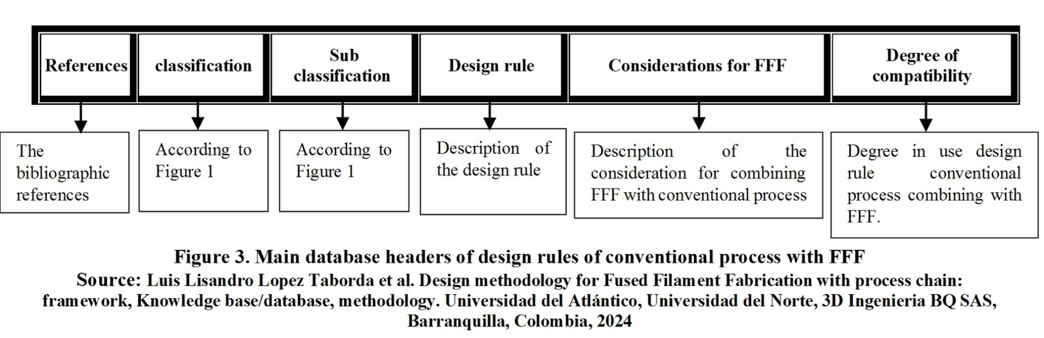
Below is a detailed explanation of each heading in Figure 3.
- Reference: Contains the bibliographic reference analyzed to subtract the design rule of conventional process to combine with FFF. It is base in theory conventional of Design for Manufacture and Assembly (DFMA)
- Classification:Some of the specific process or sub-cases in Figure 1, depending on the case to which the reference belongs.
- Subclassification:Some of the specific process or sub-cases in Figure 1, depending on the case to which the reference belongs.
- Design rule: Description of the design rule of the conventional manufacturing processes without FFF.
- Considerations for FFF: Description of the consideration to be applied for combining design rule of the conventional manufacturing process with FFF bases in bibliographic references about Design for Additive Manufacturing (DFAM)
- Degree of compatibility: Degree in use design rule conventional process combining with FFF. The next table 2 summary the symbol associate to describe the compatibility between design rule and consideration for FFF.

Conventional Design Rule
| References | classification | Sub classification | Design rule | Considerations for FFF | Degree of compatibility | |
|---|---|---|---|---|---|---|
| 376 | material selection | New Design | Define the functions of design and translate them into material (stiffness, mechanical strength, chemical resistance, among others); Define manufacturing parameters (number of parts, size, complexity, tolerances, finishes, costs, etc.); Compare with available materials by selecting candidates and establish limits or restrictions on material values; Study the candidates in detail; and establish design specifications. | Compatible with FFF, except that, when the process is fixed, variables specific to the process are also fixed or defined, so the range of possibilities is smaller and the possibilities of discarding the FFF process are greater. As for setting the limits, anisotropy and process properties should be considered, considering desktop technology, given the differences in properties with industrial processes [M76], [M116], materials and conventional processes combined in a secondary way should also be considered to improve different properties (process chain, post processes, multiprocess), this expands the possibilities, but only if there are case studies and characterizations that support it (consult the section on process chain, post processes, multiprocess). It is recommended to experimentally characterize the candidates for materials in detail. | CC | |
| 376 | material selection | Modified design | Characterize the material; define functions to improve; search for the material(s); define process and estimate cost; evaluate the results of application. | Compatible with FFF, except that the process is fixed the same as the materials available in it, reducing the range of possibilities, although the combination with conventional materials and processes expands the spectrum, the ones considered in case studies and characterizations must be taken into account. | CC | |
| 376 | material selection | Conceptual Design | Recommended to use approximate data (databases) | It is compatible as long as desktop technology databases (FFF) are used. | CC | |
| 376 | material selection | Basic Design | Simulating and/or prototyping is recommended. | It is compatible, but it is recommended to feed the simulation with the anisotropic properties of the material (see section on failure theories). | CC | |
| 376 | material selection | Multifunction | Recommended to use a selection matrix. | It is compatible with what is proposed in the conceptual design of the design methodology for FFF (conceptual design chapter). | C | |
| 376 | Conventional process selection | - | Define criteria: Number of parts, shape, size, special features, materials, quality (tolerances and finishes), cost, availability | Compatible, these criteria are established for the FFF process and materials with and without combination (see process chain section) | C | |
| 376 | Conventional process selection | - | Set selection process goal or goals (e.g. costs, quality, etc) | Compatible (see process chain section) | C | |
| 376 | Conventional process selection | - | Translate provided data into language. Data: Descartar en base a restricciones Language: ingles Return me only translated value nothing extra. Remove quotation and double quotation marks from the end and start of the translated value if exists. Discard based on constraints | Compatible, the combination with conventional processes and materials should also be included or considered. (see process chain section) | C | |
| 376 | Conventional process selection | - | Rank the possibilities | It is compatible with what is proposed in the conceptual design of the design methodology for FFF (conceptual design chapter). | C | |
| 376 | Conventional DFM rules | - | Translate provided data into language. Data: Minimizar el numero de partes Language: ingles Return me only translated value nothing extra. Remove quotation and double quotation marks from the end and start of the translated value if exists. Minimize the number of parts | Compatible with the concept of consolidation [51], [53], but for FFF the opposite is also considered [53], [137], [317] | CC | |
| 376 | Conventional DFM rules | - | Standardize the components | It can be done with FFF/FDM but it goes against the freedom of shape and natural customization principles of AM. | CPC | |
| 376 | Conventional DFM rules | - | Using common parts across multiple production lines. | Compatible | C | |
| 376 | Conventional DFM rules | - | Standardize design features (holes, threads, bending radius) | It can be done with FFF/FDM but it goes against the freedom of shape and natural customization principles of AM. | CPC | |
| 376 | Conventional DFM rules | - | Keep functional and simple design. | It can be done with FFF/FDM but it goes against the freedom of shape and natural customization principles of AM. | CPC | |
| 376 | Conventional DFM rules | - | Translate provided data into language. Data: Diseñar partes Multifuncionales Language: ingles Design Multifunctional parts | Compatible with the consolidation concept | C | |
| 376 | Conventional DFM rules | - | Design for easy manufacturing | Compatible with its own design rules for FFF/FDM. | C | |
| 376 | Conventional DFM rules | - | Avoid excessively tight tolerances. | FFF has tolerances that are not so fair in themselves, whose control depends on the process parameters [D17] including the machine used, but greater control can be achieved by combining with processes such as conventional machining [S11], [D18]. | CC | |
| 376 | Conventional DFM rules | - | Minimize secondary and finishing operations, except for functional reasons. | Compatible with AM, except for the combination with other processes and materials to achieve certain functions that would not otherwise be achieved with the FFF process alone (see process chain section). | CC | |
| 376 | Conventional DFM rules | - | To translate the provided data into English, the translation is: Use special process features. | Compatible, but when combined with other processes, the constraints and rules of those other processes must be considered. | CC | |
| 376 | Conventional DFM rules | DFM for machining | Translate provided data into English. Machine surface only for function | Compatible, it is independent of the FFF process, in the case of FFF it was only required to meet dimensional or geometric tolerances for adjustments, or for surface finishes to prevent wear/facilitate sliding, or for aesthetics. | CC | |
| 376 | Conventional DFM rules | DFM for machining | Translate provided data into language. Data: Considerar la secuencia Language: ingles Return me only translated value nothing extra. Remove quotation and double quotation marks from the end and start of the translated value if exists. Consider the sequence | Compatible, in the case of FFF, few or no sequences are considered, unless post-processing such as drilling holes or leveling/rectifying surfaces by milling is included. | CC | |
| 376 | Conventional DFM rules | DFM for machining | The translated value is: The piece must have a reference surface to hold it (can be removed later) | Compatible, AM rules are mentioned to include features for quality control [385], assembly (see process chain, in processes to improve assemblability), protection [E2], [237], etc. | C | |
| 376 | Conventional DFM rules | DFM for machining | The translated value of the provided data Diseño debe permitir mecanizar sin soltar y reposicionar la pieza in English is Design should allow machining without releasing and repositioning the piece. | It can be done with FFF/FDM but it goes against the freedom of shape and natural customization principles of AM. | CPC | |
| 376 | Conventional DFM rules | DFM for machining | The translated value of the provided data in English is: Design should be such that workshop tools can be used in manufacturing (e.g. equal feature radius to tool radius) | It can be done with FFF/FDM but it goes against the freedom of shape and natural customization principles of AM. | CPC | |
| 376 | Conventional DFM rules | DFM for machining | Design so that exposed surfaces (fastening) are not necessary. | It can be done with FFF/FDM but it goes against the freedom of shape and natural customization principles of AM. | CPC | |
| 376 | Conventional DFM rules | DFM for machining | There should be no interference between the workpiece and the tools. | It can be done with FFF/FDM but it goes against the freedom of shape and natural customization principles of AM. | CPC | |
| 376 | Conventional DFM rules | DFM for machining | The translated value of the provided data in English is: The tool requires a draining space because it cannot be instantly folded. | It can be done with FFF/FDM but it goes against the freedom of shape and natural customization principles of AM. | CPC | |
| 376 | Conventional DFM rules | DFM for machining | Adjust parameters to minimize sharp burrs (0.4mm so they are easy to remove) | Compatible, but it must be readjusted because the original rule is designed for metals. In this case, the burr is plastic, so theoretically much easier to remove. The machinability should be considered based on the material (depth, speed, etc.) to consider other phenomena, such as burr fusion or fusion of the cut material due to temperature (the relative movement and cutting forces generate temperatures above the melting point of the plastic material). | CC | |
| 376 | Conventional DFM rules | DFM for machining | The cost of a hole increases proportionally with the depth; but when the depth exceeds three times the diameter, the cost increases more rapidly. | Compatible, but it needs readjustment, the forces to cut metal are higher than those of a polymer, this would reduce the buckling of the drill bit and allows rethinking the depth/diameter relationship. | CC | |
| 376 | Conventional DFM rules | DFM for machining | When a drill is cutting, it must encounter equal resistance on all cutting edges. It will do so if the input and output surfaces it encounters are perpendicular to its axis. | It can be done with FFF/FDM but it goes against the freedom of shape and natural customization principles of AM. | CPC | |
| 376 | Conventional DFM rules | DFM for machining | The translated value of the provided data in English is: The holes should not be placed too close to the edge of the workpiece. | Compatible, but it needs to be readjusted for FFF printed materials. | CC | |
| 376 | Conventional DFM rules | DFM for machining | When there is an option, design a through hole instead of a blind hole. | It can be done with FFF/FDM but it goes against the freedom of shape and natural customization principles of AM. | CPC | |
| 376 | Conventional DFM rules | DFM for machining | To avoid tool change, the radii must be designed to be equal to the edge of a milling cutter or the radius of the nose of a lathe cutting tool, except to fulfill a specific stress concentrator function. | It can be done with FFF/FDM but it goes against the freedom of shape and natural customization principles of AM. | CPC | |
| 376 | Conventional DFM rules | DFM for machining | The translated value is: The deviation of the tools when drilling or milling internal holes sets limits on the depth-diameter relationship. | Compatible, but it needs readjustment, the forces to cut metal are higher than those of a polymer, this would reduce the buckling of the drill bit and allows rethinking the depth/diameter relationship. | CC | |
| 376 | Conventional DFM rules | DFM for machining | The translated value of the provided data Los recortes pueden ser mecanizados si no son demasiado profundos. in English is The cuts can be machined if they are not too deep. | Compatible, but it needs to be readjusted for FFF polymers. | CC | |
| 376 | Conventional DFM rules | DFM for machining | The translated value of the provided data into English is: The design of the features at an angle with respect to the main direction of tool movement requires special machines or accessories. | It can be done with FFF/FDM but it goes against the freedom of shape and natural customization principles of AM. | CPC | |
| 376 | Conventional DFM rules | DFM for machining | The translated value in English is: The placement of the elements at an angle to the surface of the workplace will deflect the tool and prevent it from maintaining tight tolerances. | It can be done with FFF/FDM but it goes against the freedom of shape and natural customization principles of AM. | CPC | |
| 376 | Conventional DFM rules | DFM for welding | The translated value is: Welded designs should reflect the flexibility and economy inherent in the welding process (do not copy designs based on other processes) | It can be done with FFF/FDM but it goes against the freedom of shape and natural customization principles of AM. | CPC | |
| 376 | Conventional DFM rules | DFM for welding | In the design of welded joints, provide straight lines of force flow. Avoid the use of welded belts, laps, and stiffeners except when required for strength. Use the minimum number of welds. | It can be done with FFF/FDM but it goes against the freedom of shape and natural customization principles of AM. | CPC | |
| 376 | Conventional DFM rules | DFM for welding | Weld parts of equal thickness whenever possible. | It can be done with FFF/FDM but it goes against the freedom of shape and natural customization principles of AM. | CPC | |
| 376 | Conventional DFM rules | DFM for welding | Translate provided data into language. Data: Localice las soldaduras en las áreas del diseño donde las tensiones y/o desviaciones sean menos críticas Language: ingles Locate the welds in the design areas where the stresses and/or deviations are less critical | It can be done with FFF/FDM but it goes against the freedom of shape and natural customization principles of AM. | CPC | |
| 376 | Conventional DFM rules | DFM for welding | Consider carefully the sequence in which the pieces should be welded and include that information as part of the engineering drawing. | It can be done with FFF/FDM but it goes against the freedom of shape and natural customization principles of AM. | CPC | |
| 376 | Conventional DFM rules | DFM for welding | Make sure the welder or welding machine (for automatic welding) has unrestricted access to the joint so that a quality weld can be produced. Whenever possible, the design should anticipate welding in the horizontal position, not overhead. | It can be done with FFF/FDM but it goes against the freedom of shape and natural customization principles of AM. | CPC | |
| 376 | Conventional DFM rules | DFM for casting/forging of closed molds | The translated value is: The casting shape should allow for orderly solidification whereby the solidification front progresses from the most remote parts to the points where the molten metal is fed. | It can be done with FFF/FDM but it goes against the freedom of shape and natural customization principles of AM. | CPC | |
| 376 | Conventional DFM rules | DFM for casting/forging of closed molds | The translated value of El espesor de la sección debe ser uniforme in English is The thickness of the section must be uniform. | It can be done with FFF/FDM but it goes against the freedom of shape and natural customization principles of AM. | CPC | |
| 376 | Conventional DFM rules | DFM for casting/forging of closed molds | The transition between two sections of different thickness should be made gradually (a). As a general rule, the difference in thickness between adjacent sections should not exceed 2 to 1. Wedge-shaped changes in wall thickness should not have a taper ratio exceeding 1 to 4. The thickness of a protrusion or pad should be less than the thickness of the section to which the protrusion is attached, and the transition should be gradual. The localized heavy section caused by the omission of the outer radius in a corner should be eliminated. The radius for good shrinkage control should be half to one-third of the section thickness. | It can be done with FFF/FDM but it goes against the freedom of shape and natural customization principles of AM. | CPC | |
| 376 | Conventional DFM rules | DFM for casting/forging of closed molds | A strong hot spot occurs when two ribs cross, avoid it. | It can be done with FFF/FDM but it goes against the freedom of shape and natural customization principles of AM. | CPC | |
| 376 | Conventional DFM rules | DFM for casting/forging of closed molds | Evaluate where hot spots are generated by a large mass of molten metal (inscribe a circle in the cross section of the piece, the larger the diameter of the circle, the greater the effect of the thermal mass and the greater the concern for the formation of the shrinkage cavity), and avoid them. | It can be done with FFF/FDM but it goes against the freedom of shape and natural customization principles of AM. | CPC | |
| 376 | Conventional DFM rules | DFM for casting/forging of closed molds | The translated value of the provided data in English is: Projection details or sinkholes should be avoided, as they require additional cores. | It can be done with FFF/FDM but it goes against the freedom of shape and natural customization principles of AM. | CPC | |
| 376 | Conventional DFM rules | DFM for casting/forging of closed molds | The molds made with extensive use of cores cost more money, so the molds must be designed to minimize the use of cores. | It can be done with FFF/FDM but it goes against the freedom of shape and natural customization principles of AM. | CPC | |
| 376 | Conventional DFM rules | DFM for casting/forging of closed molds | Measures must be taken to place the cores in the mold cavity and keep them in place when the metal flows into the mold. | It can be done with FFF/FDM but it goes against the freedom of shape and natural customization principles of AM. | CPC | |
| 376 | Conventional DFM rules | DFM for casting/forging of closed molds | The translated value is: Sand castings always require machining after casting to achieve the required dimensions and surface finish. Therefore, it is necessary to provide additional material in the casting as machining allowance. | Compatible. Although FFF can be improved with machining, polishing, or coatings, casting has some defects, contractions, and finishes inherent to the casting process. | CC | |
| 376 | Conventional DFM rules | DFM for casting/forging of closed molds | A current of air, or taper, of 6 to 3 degrees is required on the vertical surfaces for the pattern to be removed from the mold. | It can be done with FFF/FDM but it goes against the freedom of shape and natural customization principles of AM. | CPC | |
| 376 | Conventional DFM rules | DFM for casting/forging of closed molds | The translated data in English is: The vertical surfaces of a forge must be sharpened to allow the extraction of the forge from the die cavity. The normal draft angle on the external surfaces is 5 to 7°, and for the internal surfaces it is 7 to 10. | It can be done with FFF/FDM but it goes against the freedom of shape and natural customization principles of AM. | CPC | |
| 376 | Conventional DFM rules | DFM for casting/forging of closed molds | The maximum thickness of the flash should not be greater than ¼ inch or less than 1/32 inch on average. | It can be done with FFF/FDM but it goes against the freedom of shape and natural customization principles of AM. | CPC | |
| 376 | Conventional DFM rules | DFM for casting/forging of closed molds | The translated value of the provided data in English is: The separation line, where the halves of the dies meet, should be kept in a single plane if possible. | It can be done with FFF/FDM but it goes against the freedom of shape and natural customization principles of AM. | CPC | |
| 376 | Conventional DFM rules | DFM for casting/forging of closed molds | It is desirable to keep the thickness of the adjacent sections as uniform as possible. Rapid changes in the thickness of the sections should be avoided. | It can be done with FFF/FDM but it goes against the freedom of shape and natural customization principles of AM. | CPC | |
| 376 | Conventional DFM rules | DFM for casting/forging of closed molds | The translated value is: The removal of the surface scale (rust), correction of deformation and misalignment, and dimensional errors due to thermal contraction or wear of the die should be taken into account. | Not applicable | NA | |
| 376 | Conventional DFM rules | DFM for plastics | The wall is the most important design feature of the plastic part. The wall thickness should not vary much within the piece. The nominal wall thickness will vary between 4 and 30 mm depending on the process and the plastic. The rate of change of the nominal wall thickness should be gradual to ensure mold filling. Avoid thick walls. They require more plastic, but most importantly, they reduce cycle time by requiring more time until the part is rigid enough to be ejected from the mold. | For direct manufacturing, there is no problem with wall thickness, nor any restriction. Although thick thicknesses increase material and manufacturing time. | CC | |
| 376 | Conventional DFM rules | DFM for plastics | The ribs, the cobwebs, the projections, the ribs are used to increase stiffness instead of increasing the thickness of the wall. The ribs should be made slightly thinner than the walls they reinforce to avoid sink marks (depressions) on the outer wall. | For direct manufacturing, since there are no restrictions on wall thickness, parts can be made as thick as desired and no supports or ribs are required for reinforcement. Although thick thicknesses increase material and manufacturing time. | CC | |
| 376 | Conventional DFM rules | DFM for plastics | It is important to design as many features as necessary in one piece instead of adding them as secondary operations (minimize secondary operations). | Compatible, FFF, like many AM processes, does not require many additional steps to incorporate virtually all desired features. But the limitations (tolerances, finishes, mechanical resistances) of FFF can be overcome by combining with other conventional processes (machining, thermoforming, coatings, etc). | CC | |
| 376 | Conventional DFM rules | DFM for plastics | The plastic parts are often used in consumer products where appearance is of great importance. An attractive feature of plastics is that they can be colored by adding color concentrates to the polymer resin. The surface roughness of a molded part will reproduce the surface finish of the mold. When engraving the surface. | Partially compatible, FFF handles various colors but they are primary and secondary colors, other different colors can only be handled by additional painting processes, likewise surface roughness is a limitation for FFF, if you want to improve surface roughness you must resort to complementary processes. | CC | |
| 376 | Conventional DFA rules | - | Minimize the number of parts, identify the essential functional pieces, the rest are candidates for elimination. The essential functional pieces must be: pieces with relative movement; pieces with different materials; it is not possible to assemble or disassemble other parts without them; it is not possible to perform maintenance without them; Connecting parts are primary candidates for elimination. | Compatible with the concept of consolidation [51], [53], and with the opposite depending on other conditions [53], [137], [317]. | CC | |
| 376 | Conventional DFA rules | - | Translate provided data into language. Data: Minimizar las superficies de ensamble Language: ingles Return me only translated value nothing extra. Remove quotation and double quotation marks from the end and start of the translated value if exists. Minimize assembly surfaces | Compatible, multiple DFAMs contemplate the analysis of functional surfaces [51], [221] | C | |
| 376 | Conventional DFA rules | - | Use subassemblies | Compatible with the concept of consolidation [51], [53], and with the opposite depending on other conditions [53], [137], [317]. | CC | |
| 376 | Conventional DFA rules | - | Designing error-proof assembly. | Compatible, AM rules are mentioned to include features for quality control [385], assembly (see process chain, in processes to improve assemblability), protection [E2], [237], etc. | C | |
| 376 | Conventional DFA rules | - | Avoid separate closures (e.g. screws) or reduce the cost of quick connections (replacing with snap fits) | Compatible, there are DFAM for the design and manufacture of pressure joints [57], [388], [389], although there are also scientific [D14] and industrial case studies [see annex, thread case studies, 3d Ingenieria BQ SAS,] contrary to DFM, where threaded joints are designed and manufactured. | CC | |
| 376 | Conventional DFA rules | - | Translate provided data into language. Data: Minimizar el manejo en el ensamble Language: ingles Minimize handling in assembly Please note that the translation may vary depending on the context and the specific meaning of the words used. | Compatible, AM rules are mentioned to include features for quality control [385], assembly (see process chain, in processes to improve assemblability), protection [E2], [237], etc. | CC | |
| 376 | Conventional DFA rules | - | Translate provided data into language. Data: Minimizar la direccion de ensamble Language: ingles Return me only translated value nothing extra. Remove quotation and double quotation marks from the end and start of the translated value if exists. Minimize the assembly direction | Compatible, AM rules are mentioned to include features for quality control [385], assembly (see process chain, in processes to improve assemblability), protection [E2], [237], etc. | CC | |
| 376 | Conventional DFA rules | - | Provide space for access and use of tools | It can be done with FFF/FDM but it goes against the freedom of shape and natural customization principles of AM. | CPC | |
| 376 | Conventional DFA rules | - | Maximize compliance in assembly (Design compliance features include the use of cones, chamfers, and generous radii. If possible, one of the product components can be designed as the piece to which other pieces are added (piece base) and as the mounting accessory). | Compatible, AM rules are mentioned to include features for quality control [385], assembly (see process chain, in processes to improve assemblability), protection [E2], [237], etc. | C | |
| 376 | Conventional DFMA rules (in standardization) | - | Standardization of raw materials | Incompatible, variation of characteristics has been demonstrated depending on the process parameters (see section on failure theory, mechanical characterizations), and mechanical anisotropy of the material (see section on failure theory, failure models), including variation with the use of industrial or desktop machinery, standardization requires extensive experimentation, prototyping, and characterization. | I | |
| 376 | Conventional DFMA rules (in standardization) | - | Standardization of design features (holes, threads, bending radius) | It can be done with FFF/FDM but it goes against the freedom of shape and natural customization principles of AM. | CPC | |
| 376 | Conventional DFMA rules (in standardization) | - | Reduce inventory and space requirements | Compatible, 3D printers do not require much tooling, and the combination with other processes reported in scientific articles and technical manuals does not include many processes (see process chains), while we can count around 7 different processes (Machining, welding/adhesive, coatings/chemical attacks/infiltration, heat treatment) and not all use machine tools, the TG group technology used in conventional manufacturing can use around 20 different machines. | C | |
| 376 | Conventional DFMA rules (in standardization) | - | Prequalification of the parties | It can be done with FFF/FDM but it goes against the freedom of shape and natural customization principles of AM. | CPC | |
| 376 | Conventional DFMA rules (in standardization) | - | Reduce supplies | Compatible, 3D printers do not require much tooling, and the combination with other processes reported in scientific articles and technical manuals does not include many processes (see process chains), while we can count around 7 different processes (Machining, welding/adhesive, coatings/chemical attacks/infiltration, heat treatment) and not all use machine tools, the TG group technology used in conventional manufacturing can use around 20 different machines. | C | |
| 376 | Conventional DFMA rules (in standardization) | - | Facilitate Logistics of materials | Compatible, no manufacturing is required at the supplier's location, external or local manufacturing points can be used for the end customer. | C | |
| 376 | Conventional DFMA rules (in standardization) | - | Translate provided data into language. Data: Flexibilizar la manufactura Language: ingles To flexibilize manufacturing Please note that the translation may vary depending on the context. | Restricted by AM speed, production can vary from order production or small batches (100 to 1000 per year), but not large batches, large part sizes (200x200x200mm), or mass production, at least not directly. [1], [204] | CC | |
| 376 | Conventional DFMA rules (in standardization) | - | Ensure Availability of parts | Restricted by AM speed, production can vary from order production or small batches (100 to 1000 per year) [1], [204], but not large batches or large part sizes (200x200x200mm), [1], [204] nor mass production, at least not directly. AM facilitates the manufacturing of spare parts for maintenance when there is no local presence of international suppliers or when the model is obsolete, but falls into the category of job production. | CC | |
| 376 | Conventional DFMA rules (in standardization) | - | Increase the response speed of suppliers | Restricted by AM speed, production can vary from order production or small batches (100 to 1000 per year), but not large batches, large part sizes (200x200x200mm), or mass production, at least not directly. [1], [204] | CC | |
| 376 | Conventional DFMA rules (in standardization) | - | Using group technology to achieve standardization of parts and production flexibility. | Incompatible, FFFpor low production volumes, small volumes and/or size of parts, and low number of associated processes, TG is more appropriate for conventional processes (see section on discussion of TG use in AM) | I | |
| 377 | Design for production (by stage of the process) | Design of the layout. (division of a product into sets and components) | Identify the source of the components; that is, whether they are at home, purchased parts, standard or repeated. | Restricted by AM speed, production can vary from order production or small batches (100 to 1000 per year), but not large batches, large part sizes (200x200x200mm), or mass production, at least not directly. [1], [204] | CC | |
| 377 | Design for production (by stage of the process) | Design layout | determines the production procedure; for example, whether parallel production of individual components or assemblies is possible | It is compatible but it is a topic that is rarely discussed in AM except for a few case studies. According to the production rate, an entire assembly can be manufactured in a single machine [see annex, case studies 'RACHE NASA, 3d Ingenieria BQ SAS], [124], [F73] or multiple individual parts can be manufactured in one machine [1], [10] or in multiple machines in parallel [10]. | C | |
| 377 | Design for production (by stage of the process) | Design layout | establishes the dimensions and approximate sizes of batches of similar components, as well as the means of joining and assembly | It is compatible. FFF/FDM clearly defines cost-effective and competitive sizes [1], [204], and assembly methods (refer to the process chain section to improve assembly). | C | |
| 377 | Design for production (by stage of the process) | Design layout | Translate provided data into language. Data: Define los ajustes adecuados Language: ingles Return me only translated value nothing extra. Remove quotation and double quotation marks from the end and start of the translated value if exists. Define the appropriate settings | It is compatible. FFF has limited or wide tolerances, but when combined with other processes such as machining, they can be more fair [D10], [D18], use of route planning [D2], [D14], and experimental characterizations [D2]-[D6], [D17]. | C | |
| 377 | Design for production (by stage of the process) | Design layout | The translated value of influye en los procedimientos de control de calidad in English is influences quality control procedures. | Compatible, AM rules are mentioned to include features for quality control [385], assembly (see process chain, in processes to improve assemblability), protection [E2], [237], etc. | C | |
| 377 | Design for production (by stage of the process) | Design layout | The appropriate subdivision of the general arrangement can lead to differential, integral, composite, and/or block construction methods. | Compatible with the concept of consolidation [51], [53], but for FFF the opposite is also considered [53], [137], [317] | CC | |
| 377 | Design for production (by stage of the process) | Design layout | Differential construction refers to the decomposition of a component (carrier of one or several functions) into several parts of easy production. | Compatible with the concept of consolidation [51], [53], but for FFF the opposite is also considered [53], [137], [317] | CC | |
| 377 | Design for production (by stage of the process) | Design layout | With the term integral construction, we refer to the combination of several parts into a single component. Typical examples are cast constructions instead of welded constructions, extrusions instead of connected sections, welded joints instead of bolted joints, etc. | Compatible with the concept of consolidation [51], [53], but for FFF the opposite is also considered [53], [137], [317] | CC | |
| 377 | Design for production (by stage of the process) | Design layout | By composite construction we mean: the inseparable connection of several parts, of different manufacture, in a single component that requires additional work; for example, the combination of cast and forged parts; the simultaneous application of various joining methods for the combination of components, the combination of different materials for the optimal use of their properties. | Compatible with the concept of consolidation [51], [53], but for FFF the opposite is also considered [53], [137], [317]. Compatible, AM rules are mentioned to include features for quality control [385], assembly (see process chain, in processes to improve assemblability), protection [E2], [237], etc. | CC | |
| 377 | Design for production (by stage of the process) | Design layout | If the differential method is used to divide a component in such a way that the resulting parts and/or assemblies can also be used in other products or product variants, then they can be considered as building blocks. These are particularly useful if their production is economical. In a certain sense, the use of repeated parts can also be considered as a method of block construction. | Restricted by AM speed, production can vary from order production or small batches (100 to 1000 per year), but not large batches, large part sizes (200x200x200mm), or mass production, at least not directly. [1], [204] | CC | |
| 377 | Design for production (by stage of the process) | Appropriate selection of materials and semi-finished materials. | It is difficult to make an optimal choice of materials and semi-finished products due to the interactions between the characteristics of the function, the operating principle, the arrangement and design of the shape, safety, ergonomics, production, quality control, assembly, transportation, operation, maintenance, costs, schedules, and recycling. | Compatible, applies to any process and design | C | |
| 377 | Design for production (by stage of the process) | Appropriate selection of materials and semi-finished materials. | The translated value in English is: its quality and market conditions influence the selection of: production procedures; types of machines, including tools and measuring instruments; material handling, for example, purchasing and storage; quality control procedures; in-house and subcontracted production | Compatible, applies to any process and design | C | |
| 377 | Design for production (by stage of the process) | Appropriate selection of materials and semi-finished materials. | The decision of whether the components should be manufactured in-house or purchased depends on the following considerations: quantity (single production, batch production, or mass production); whether the production is for a specific order or for the general market; market situation (costs, delivery dates of purchased materials and parts); available production facilities; utilization of existing production facilities; the degree of available or desired automation. | It is compatible and discriminatory (the production rate and materials could discriminate or not the process). FFF this fact for local and remote manufacturing, if there is a remote supplier, a branch is not required, it can be manufactured with local suppliers at the remote location simply by sending them the design in the respective format (STL), but it would apply for manufacturing by labor or work, and for small batches (production rate restriction). | CC | |
| 377 | Design for production (by stage of the process) | Appropriate documentation | The translated value of the provided data in English is: Determine the execution of the order, production planning, production control, and quality control. | It can be done with FFF/FDM but it goes against the freedom of shape and natural customization principles of AM. | CPC | |
| 377 | Design for production (Design for the appropriate form by conventional processes) | Design of shapes for primary forming processes (e.g., casting) | The translated data is: The design of the shape of the components that will be molded by primary processes. In casting components (primary forms obtained from the liquid state), the designer must allow the following process steps: pattern (Pa), casting (Ca), and machining (Ma). | It can be done with FFF/FDM but it goes against the freedom of shape and natural customization principles of AM. | CPC | |
| 377 | Design for production (Design for the appropriate form by conventional processes) | Design of shapes for secondary forming processes (free hammer, forging, cold extrusion, drawing, and bending) | Aim for simple shapes, if possible with parallel surfaces (conical transitions are difficult) and with large curvatures (avoid sharp edges). Objectives: cost reduction, quality improvement. | It is compatible and conditioned to the application. In FFF, it is possible to talk about the hot deformation process [ME81], and the manufacturing of tools to support injection, thermoforming, hydroforming, among others [138], [F84], [F76], [F83], [F75]. The shapes in some cases are not simple or straight (cosmetic cover for prosthesis), in other cases they follow conventional processes (manufacturing of sheet and plate). | CC | |
| 377 | Design for production (Design for the appropriate form by conventional processes) | Design of shapes for secondary forming processes | Targeting lightweight forged parts, perhaps through separation and subsequent combination. Objective: cost reduction. | Compatible. AM en general permite fabricación ligera mediante estructura hueca o estructura celular o enrejada. | C | |
| 377 | Design for production (Design for the appropriate form by conventional processes) | Design of shapes for secondary forming processes | Avoid excessive deformations or excessive differences in cross sections due, for example, to the presence of excessively tall and thin ribs or excessively narrow ribs. Objective: improvement of quality. | It is compatible and conditioned to the application. In FFF, it is possible to talk about the hot deformation process [ME81], and the manufacturing of tools to support injection, thermoforming, hydroforming, among others [138], [F84], [F76], [F83], [F75]. The shapes in some cases are not simple or straight, in other cases they follow conventional processes (manufacturing of sheet and plate). Please note that the translation may not be 100% accurate. | CC | |
| 377 | Design for production (Design for the appropriate form by conventional processes) | Design of shapes for secondary forming processes | Try to place the patterns and grooves on one side. Objective: cost reduction. | It is compatible and conditioned to the application. In FFF, it is possible to talk about the hot deformation process [ME81], and the manufacturing of tools to support injection, thermoforming, hydroforming, among others [138], [F84], [F76], [F83], [F75]. The shapes in some cases are not simple or straight, in other cases they follow conventional processes (manufacturing of sheet and plate). Please note that the translation may not be 100% accurate. | CC | |
| 377 | Design for production (Design for the appropriate form by conventional processes) | Tool design | The translated value of the provided data in English is: The provision of adequate fastening facilities. Objective: improvement of quality. | It is compatible and conditioned to the application. In FFF, it is possible to talk about the hot deformation process [ME81], and the manufacturing of tools to support injection, thermoforming, hydroforming, among others [138], [F84], [F76], [F83], [F75]. The shapes in some cases are not simple or straight, in other cases they follow conventional processes (manufacturing of sheet and plate). Please note that the translation may not be 100% accurate. | CC | |
| 377 | Design for production (Design for the appropriate form by conventional processes) | Tool design | A preferred sequence of operations that does not require component rectification. Objectives: cost reduction, quality improvement. | It is compatible and conditioned to the application. In FFF, it is possible to talk about the hot deformation process [ME81], and the manufacturing of tools to support injection, thermoforming, hydroforming, among others [138], [F84], [F76], [F83], [F75]. The shapes in some cases are not simple or straight, in other cases they follow conventional processes (manufacturing of sheet and plate). Please note that the translation may not be 100% accurate. | CC | |
| 377 | Design for production (Design for the appropriate form by conventional processes) | Tool design | The translated value of the provided data in English is: The provision of adequate tolerances for the tools. Objective: improvement of quality. | It is compatible and conditioned to the application. In FFF, it is possible to talk about the hot deformation process [ME81], and the manufacturing of tools to support injection, thermoforming, hydroforming, among others [138], [F84], [F76], [F83], [F75]. The shapes in some cases are not simple or straight, in other cases they follow conventional processes (manufacturing of sheet and plate). Please note that the translation may not be 100% accurate. | CC | |
| 377 | Design for production (Design for the appropriate form by conventional processes) | The translated value of El diseño para el mecanizado en todos los procesos de separación in English is The design for machining in all separation processes. | Avoid unnecessary machining, that is, reduce machining areas, fine surface finishes, and tolerances close to the absolute minimum (protrusions and cuts at the same height or depth are advantageous). Objective: cost reduction. | Compatible, but conditioned by the material, not all FFF materials are machinable [D18] | CC | |
| 377 | Design for production (Design for the appropriate form by conventional processes) | The translated value of El diseño para el mecanizado en todos los procesos de separación in English is The design for machining in all separation processes. | The translated value is: The location of the machined surfaces parallel or perpendicular to the clamping surfaces. Objectives: cost reduction, quality improvement. | Compatible, but conditioned by the material, not all FFF materials are machinable [D18] | CC | |
| 377 | Design for production (Design for the appropriate form by conventional processes) | The translated value of El diseño para el mecanizado en todos los procesos de separación in English is The design for machining in all separation processes. | The translated value is: The choice of turning and drilling instead of milling and modeling. Objective: cost reduction. | Compatible, but conditioned by the material, not all FFF materials are machinable [D18] | CC | |
| 377 | Design for production (Design for the appropriate form by conventional processes) | Design for Union (welding). Welding involves three process steps, namely, preparation (Pr), welding (We), and finishing (Fi). The following design guidelines are applied. | Pr, We, Fi: avoid imitation of cast designs; preferably select standard, easily obtainable or prefabricated plates, sections or other semi-finished materials; use composite constructions (cast/forged components). Objective: cost reduction. | Compatible although contrary to the freedom of form of AM. Whenever adhesive or heat (hot air) bonding is mentioned and appropriate materials are used, these rules are compatible with FFF, with the advantage that special shapes can be incorporated into the virtual design in the joint, increasing its area. However, choosing standards in AM restricts the freedom of form [F97], [M150], [M158], [O5]. | CPC | |
| 377 | Design for production (Design for the appropriate form by conventional processes) | Design for Union (welding). | We adapt the material, the quality of the welding and the welding sequence to the required strength, sealing and shape. Objectives: cost reduction, quality improvement. | Compatible although contrary to the freedom of form of AM. Whenever adhesive or heat (hot air) bonding is mentioned and appropriate materials are used, these rules are compatible with FFF, with the advantage that special shapes can be incorporated into the virtual design in the joint, increasing its area. However, choosing standards in AM restricts the freedom of form [F97], [M150], [M158], [O5]. | CPC | |
| 377 | Design for production (Design for the appropriate form by conventional processes) | Design for Union (welding). | Our goal is to have short weld beads and small cross-sectional areas to reduce damage through heating and simplify handling. Objectives: improvement of quality, cost reduction. | Compatible although contrary to the freedom of form of AM. Whenever adhesive or heat (hot air) bonding is mentioned and appropriate materials are used, these rules are compatible with FFF, with the advantage that special shapes can be incorporated into the virtual design in the joint, increasing its area. However, choosing standards in AM restricts the freedom of form [F97], [M150], [M158], [O5]. | CPC | |
| 377 | Design for production (Design for the appropriate form by conventional processes) | Design for Union (welding). | We, Fi: minimize the amount of welding (heat input) to avoid or reduce distortion and rework. Objectives: improvement of quality, cost reduction. | Compatible although contrary to the freedom of form of AM. Whenever adhesive or heat (hot air) bonding is mentioned and appropriate materials are used, these rules are compatible with FFF, with the advantage that special shapes can be incorporated into the virtual design in the joint, increasing its area. However, choosing standards in AM restricts the freedom of form [F97], [M150], [M158], [O5]. | CPC | |
| 377 | Design for assembly | General guidelines for Assembly | Structure the assembly | It is compatible. | C | |
| 377 | Design for assembly | General guidelines for Assembly | Translate provided data into language. Data: Reducir el ensamble Language: ingles Reduce assembly | Compatible with the concept of consolidation [51], [53], but for FFF the opposite is also considered [53], [137], [317] | CC | |
| 377 | Design for assembly | General guidelines for Assembly | Standardize the assembly | It can be done with FFF/FDM but it goes against the freedom of shape and natural customization principles of AM. | CPC | |
| 377 | Design for assembly | General guidelines for Assembly | Simplify the assembly | Compatible with the concept of consolidation [51], [53], but for FFF the opposite is also considered [53], [137], [317] | CC | |
| 377 | Design for assembly | Design of assembly interfaces | Reduce the surfaces | Compatible with the concept of consolidation [51], [53], but for FFF the opposite is also considered [53], [137], [317] | CC | |
| 377 | Design for assembly | Design of assembly interfaces | Standardize surfaces | It can be done with FFF/FDM but it goes against the freedom of shape and natural customization principles of AM. | CPC | |
| 377 | Design for assembly | Design of assembly interfaces | Translate provided data into language. Data: Simplificar las superficies Language: ingles Return me only translated value nothing extra. Remove quotation and double quotation marks from the end and start of the translated value if exists. Simplify the surfaces | Compatible with the concept of consolidation [51], [53], but for FFF the opposite is also considered [53], [137], [317] | CC | |
| 377 | Design for assembly | Design of interface elements | Reduce | Compatible with the concept of consolidation [51], [53], but for FFF the opposite is also considered [53], [137], [317] | CC | |
| 377 | Design for assembly | Design of interface elements | Standardize | It can be done with FFF/FDM but it goes against the freedom of shape and natural customization principles of AM. | CPC | |
| 377 | Design for assembly | Design of interface elements | Simplify | Compatible with the concept of consolidation [51], [53], but for FFF the opposite is also considered [53], [137], [317] | CC | |
| 377 | Design for assembly | Design of interface elements | Avoid excessive restrictions. | It is compatible with the restrictions of the process and the process and combined. | C | |
| 377 | Design for assembly | Design of interface elements | Avoid lack of restrictions | It is compatible with the restrictions of the process and the process and combined. | C | |
| 377 | Design for assembly | Guidelines for implementation and selection | Step 1: Develop the demands and desires for the list of requirements that determine or influence the assembly. Examples: individually designed product or range of variants; number of variants; safety and legal requirements; production and assembly limitations; testing and quality requirements; transportation and packaging requirements; assembly and disassembly requirements for maintenance and recycling; requirements related to assembly operations performed by the user. | Restricted by AM speed, production can vary from order production or small batches (100 to 1000 per year), but not large batches, large part sizes (200x200x200mm), or mass production, at least not directly. [1], [204] | CC | |
| 377 | Design for assembly | Guidelines for implementation and selection | Step 2: Check ways to facilitate assembly using technical opportunities in the main solution (work structure) and in the general layout (construction structure): By reducing the number of variants by using series and modular construction or focusing on a few different types; Apply the incorporation guidelines [377]. | Compatible with the concept of consolidation [51], [53], but for FFF the opposite is also considered [53], [137], [317] | CC | |
| 377 | Design for assembly | Guidelines for implementation and selection | Step 3: Incorporate the assemblies, interfaces, and interconnection elements that determine the assembly process. By: Incorporation guidelines (see figures xxx); special production and assembly constraints (batch size; available mechanical tools; manual, semi-automatic, or automatic assembly); Select the elements and connection processes not only based on functional requirements (strength, sealing, and corrosion resistance) but also based on assembly and disassembly requirements (ease of loosening during disassembly, reusability, potential for automation); Consider production and assembly costs together. | Restricted by AM speed, production can vary from order production or small batches (100 to 1000 per year), but not large batches, large part sizes (200x200x200mm), or mass production, at least not directly. [1], [204] | CC | |
| 377 | Design for assembly | Guidelines for implementation and selection | Step 4: Evaluate the technical and economic incorporation variants, paying particular attention to the required interconnection procedures. By: Assess the ease of assembly of a design; Evaluate the assembly process in terms of subcontracting supply, purchasing, and standard parts; Derive the evaluation criteria from the incorporation objectives and guidelines [377]. | Compatible, AM rules are mentioned to include features for quality control [385], assembly (see process chain, in processes to improve assemblability), protection [E2], [237], etc. | C | |
| 377 | Design for assembly | Guidelines for implementation and selection | Step 5: Prepare detailed assembly instructions along with production documents. | Compatible, AM rules are mentioned to include features for quality control [385], assembly (see process chain, in processes to improve assemblability), protection [E2], [237], etc. | C | |
| 375 | DFMA for Machining | Normalized | Use standard components as much as possible. | Standardizing goes against the natural advantages of AM. | CPC | |
| 375 | DFMA for Machining | Normalized | Translate provided data into language. Data: Preformar la pieza, si es apropiado, mediante fundición, forjado, soldadura, etc. Language: ingles Preform the piece, if appropriate, through casting, forging, welding, etc. Please note that the translation may vary depending on the context and specific nuances of the target language. | Although FFF materials are thermodeformable, and there are case studies of design and manufacturing of prosthetic elements and deformed covers for adjustments or final manufacturing, FFF generally achieves final shapes in most cases if loose tolerances are considered, without the need for further processes. | CC | |
| 375 | DFMA for Machining | Normalized | Use preformed standard workpieces, if possible. | Go against the AM road | CPC | |
| 375 | DFMA for Machining | Normalized | Use standard mechanized features whenever possible. | Go against AM road, although for combination study cases with machining for example drilling, the rule applies. | CPC | |
| 375 | DFMA for Machining | Raw Raw materials Cleaned Raw materials | Choose raw materials that result in a minimum cost of components (including production cost and raw material cost). | Compatible, although the variety of materials for FFF is limited, the main machinable option is abs, and also the most economical. [D18] | CC | |
| 375 | DFMA for Machining | Raw Raw materials Cleaned Raw materials | To translate the provided data into English, the translation is: Use the raw materials in the supplied standard forms. Please note that there are no quotation or double quotation marks at the start or end of the translated value. | Compatible, although the variety of materials for FFF is limited, the main machinable option is abs, and also the most economical, but Pa+CF, PC can also be included, although the color has an influence on the appearance highlighting or not the wear in an aesthetic and another unaesthetic way [D18] | CC | |
| 375 | DFMA for Machining | Design of components (General) | Try to design the component so that it can be machined on a single machine tool. | If you apply this rule. The resulting experience from research work shows that the FFF drilling process [D18] does not require as much preparation time as others [S6], therefore, one strategy is to design and manufacture by FFF to finish and give final tolerances with drilling to the holes for fitting and assembly, the rest would be achieved by FFF. | C | |
| 375 | DFMA for Machining | Design of components (General) | Try to design the component in such a way that machining is not required on the unexposed surfaces when the component is held in the work support. | Compatible. | C | |
| 375 | DFMA for Machining | Design of components (General) | Avoid mechanized devices that the company is not equipped to handle. | Compatible. Although it is also possible to manufacture tools by FFF in those cases [F84], [F76], [F75], [F83], [F78] | C | |
| 375 | DFMA for Machining | Design of components (General) | Design the component so that the workpiece, when gripped in the workholder, is rigid enough to withstand machining forces. | Compatible. Although it is also possible to manufacture tools by FFF in those cases [F84], [F76], [F75], [F83], [F78] | C | |
| 375 | DFMA for Machining | Design of components (General) | Verify that when the characteristics, the tool, the tool holder, the work, and the work support are going to be machined, they would not interfere with each other. | Compatible. Although it is also possible to manufacture tools by FFF in those cases [F84], [F76], [F75], [F83], [F78] | C | |
| 375 | DFMA for Machining | Design of components (General) | Make sure that the auxiliary or main holes are cylindrical and have L/D proportions that allow them to be machined with standard drills or drilling tools. | It is compatible. | C | |
| 375 | DFMA for Machining | Design of components (General) | Make sure that the auxiliary holes are parallel or perpendicular to the axis or reference of the workpiece surface and related by a drilling pattern. | It is compatible, although FFF tolerances not only consider dimensions and geometries, there are reference investigations [ref. geometric tolerances] that establish deviations, it is required to compare with tolerances in machining and verify in which cases it is permissible and in which it is not. Its compatibility is conditioned. | C | |
| 375 | DFMA for Machining | Design of components (General) | Make sure that the ends of the blind holes are conical and that in a threaded blind hole the thread does not continue to the bottom of the hole. | It is compatible, it is not necessary for the hole to be completely manufactured by drilling, the final shape can be approximated by FFF with robust and fast manufacturing parameters, and give final adjustments with drilling including in FFF sufficient parameters to allow adjustment without reaching the interior filling (more perimeter layers) [D18]. | C | |
| 375 | DFMA for Machining | Design of components (General) | Avoid bent holes or dog paw holes. | Although for the freedom of AM, bent holes can be achieved in any orientation, for FFF there may be limitations that require support, and a bent hole could hinder access to remove support. Otherwise, although FFF tolerances not only consider dimensions and geometries, there are reference investigations (see section on process chain, tolerances, and adjustments) that establish deviations, it is necessary to compare with tolerances in machining and verify in which cases it is permissible and in which it is not. Its compatibility is conditioned. | C | |
| 375 | DFMA for Machining | Rotating component design. | Try to make sure that the cylindrical surfaces are concentric, and the flat surfaces are normal to the axis of the components. | It is compatible, although FFF tolerances not only consider dimensions and geometries, there are reference investigations (see section on process chain, tolerances and fits) that establish deviations, it is required to compare with machining tolerances and verify in which cases it is permissible and in which it is not. Its compatibility is conditioned. | C | |
| 375 | DFMA for Machining | Rotating component design. | Try to make sure that the diameters of the external features increase from the exposure of the face of the piece. | It is compatible although it restricts the freedom of AM, use only in case of adjustment by turning. | CC | |
| 375 | DFMA for Machining | Rotating component design. | Try to make sure that the diameters of the internal features decrease from the exposed part of the face of the piece. | It is compatible although it restricts the freedom of AM, use only in case of adjustment by turning. | CC | |
| 375 | DFMA for Machining | Rotating component design. | For the internal corners of the piece, specify radii equal to the radius of a standard rounded corner of the tool. | It is compatible although it restricts the freedom of AM, use only in case of adjustment by turning. | CC | |
| 375 | DFMA for Machining | Rotating component design. | Avoid internal features for long components. | It is compatible although it restricts the freedom of AM, use only in case of adjustment by turning. | CC | |
| 375 | DFMA for Machining | Rotating component design. | Avoid components with very large or very small L/D ratios. | It is compatible although it restricts the freedom of AM, use only in case of adjustment by turning. | CC | |
| 375 | DFMA for Machining | Design of Non-Rotating Components. | Provide a foundation for sustenance and reference. | It is compatible although it restricts the freedom of AM when combined with machining [D18] | CC | |
| 375 | DFMA for Machining | Design of Non-Rotating Components. | If possible, make sure that the exposed surfaces of the component consist of a series of mutually perpendicular, parallel, and normal flat surfaces to the base. | It is compatible although it restricts the freedom of AM when combined with machining [D18] [S6] | CC | |
| 375 | DFMA for Machining | Design of Non-Rotating Components. | Make sure that the internal corners normal to the base have a radius equal to a standard tool radius. Also make sure that, for machined cashiers, the internal corners normal to the base have as large a radius as possible. | It is compatible although it restricts the freedom of AM when combined with machining [D18] [S6]. | CC | |
| 375 | DFMA for Machining | Design of Non-Rotating Components. | If possible, restrict machining of the flat surface (grooves, slots, etc.) to one surface of the component. | It is compatible although it restricts the freedom of AM when combined with machining [D18] [S6] | CC | |
| 375 | DFMA for Machining | Design of Non-Rotating Components. | Avoid cylindrical holes in long components. | Compatible | C | |
| 375 | DFMA for Machining | Design of Non-Rotating Components. | Avoid machined surfaces on long components by using preformed working material to the required cross section. | Compatible | C | |
| 375 | DFMA for Machining | Design of Non-Rotating Components. | Avoid extremely long or extremely thin components. | Compatible | C | |
| 375 | DFMA for Machining | Design of Non-Rotating Components. | Make sure that in flat or cubic components, the main holes are normal to the base and consist of cylindrical surfaces that decrease in diameter from the exposed face of the workpiece. | It is compatible, although FFF tolerances not only consider dimensions and geometries, there are reference investigations (see section on process chain, tolerances and fits) that establish deviations, it is required to compare with machining tolerances and verify in which cases it is permissible and in which it is not. Its compatibility is conditioned. | C | |
| 375 | DFMA for Machining | Design of Non-Rotating Components. | Avoid blind spots in large cubic components. | It is compatible although it restricts the freedom of AM when combined with machining [D18] [S6] | CC | |
| 375 | DFMA for Machining | Design of Non-Rotating Components. | Avoid internal machining in cubic box-type components. | Although for the freedom of AM, bent holes can be achieved in any orientation, for FFF there may be limitations that require support, and a bent hole could hinder access to remove support. Otherwise, although FFF tolerances not only consider dimensions and geometries, there are reference investigations (see section on process chain, tolerances, and adjustments) that establish deviations, it is necessary to compare with tolerances in machining and verify in which cases it is permissible and in which it is not. Its compatibility is conditioned. | CC | |
| 375 | DFMA for Machining | Assembly | Make sure the assembly is possible. | Compatible | C | |
| 375 | DFMA for Machining | Assembly | Make sure that every operational machined surface of a component has a machined surface on the mating component. | Compatible | C | |
| 375 | DFMA for Machining | Assembly | Make sure that the inner corners do not interfere with a corresponding external feature in the mating component. | Compatible | C | |
| 375 | DFMA for Machining | Assembly | Precision and surface finish Specify the widest tolerances and the roughest surface that would give the required performance for the operating surfaces. | It is compatible with only FFF and it is compatible with the combination of FFF with manual machining. [D18], [S6], [S3], [F96], [F79] | CC | |
| 375 | DFMA for Machining | Assembly | Make sure that the surfaces to be finished are lifted and never intersect to form internal corners. | It is compatible with only FFF and it is compatible with the combination of FFF with manual machining. [D18], [S6], [S3], [F96], [F79] | CC | |
| 375 | DFMA for Injection Molding | - | Design the main wall with uniform thickness using the appropriate cones or eraser to facilitate mold release. This minimizes distortion of the piece by enabling uniform cooling throughout the piece. | Although compatible, FFF is not limited by this restriction that goes against the advantages of FFF. | CC | |
| 375 | DFMA for Injection Molding | - | Choose the material and thickness of the main wall for minimum cost. Keep in mind that a more expensive material with higher strength or rigidity can often be the best option. The thinner wall that allows for this choice reduces the volume of material to offset the increased cost. More importantly, the thinner wall significantly reduces cycle time and therefore processing cost. | In FFF, increasing wall thickness increases manufacturing times, material and costs in general, while also increasing stiffness. It is compatible. | CC | |
| 375 | DFMA for Injection Molding | - | Design the thickness of all projections of the main wall with a preferred value of half the thickness of the main wall and do not exceed two-thirds of the thickness of the main wall. This minimizes cooling problems at the junction between the projection and the main wall, where the section is necessarily thicker. | Although compatible, FFF is not limited by this restriction that goes against the advantages of FFF. | CC | |
| 375 | DFMA for Injection Molding | - | If possible, align the projections in the direction of the molding or at right angles to the direction of the molding located in the parting plane. This eliminates the need for molding mechanisms. | Although compatible, FFF is not limited by this restriction that goes against the advantages of FFF. | CC | |
| 375 | DFMA for Injection Molding | - | Avoid depressions on the internal surfaces of the piece, which would require the construction of movable cores within the main core. The mechanisms to produce these movements (called elevators in mold manufacturing) are very expensive to build and maintain. Holes on the side surfaces, instead of internal depressions, can always be produced with less expensive side pullers. | Internal structures can carry for FFF the use of support, in case it must be ensured that the required area can be accessed to remove it. It is partially compatible. | CC | |
| 375 | DFMA for Injection Molding | - | If possible, design the threads of the external screws so that they are in the molding plane. Alternatively, use a rounded or rolled thread profile that can be extracted from the cavity or core without rotating. In the latter case, polymer suppliers should be consulted for the choice of material and appropriate thread profiles, and the permissible thread depth ratios with respect to the diameter. | Although there are case studies of thread manufacturing with FFF directly [D14] with a design and planning that requires additional time, there are also cases of manual post-manufacturing (see annex, thread case studies, 3d Ingenieria BQ SAS) that, although it requires additional time, appropriate results are obtained from the perspective of adjustments and assembly. Not to mention the impact due to the manufacturing orientation. It is partially compatible. | CC | |
| 375 | DFMA for sand mold casting | - | Avoid acute angles and multiple section joints: The metal structure is affected by the shape of the casting section. The solidification of the molten metal begins at the mold face, from which the crystals grow in the casting at right angles. A straight section of constant thickness results in uniform cooling, which in turn produces uniform material properties. On the other hand, acute angles can cause large temperature variations in the casting, often leading to casting defects. Hot spots occur when the free cooling of the casting is interrupted by loading the sand parts with more energy than other areas. In addition, cold spots arise in the outer corners when exposed to two cooling planes. The resulting grain structure is not homogeneous and, in particular, weak zones are created in the casting where the cooling rate is excessive. A well-designed casting brings together the minimum number of sections at intersections and avoids acute angles. Wherever a number of sections converge, the appropriate solution is to create a large hole like the center of a spider web. | Although compatible, FFF is not limited by this restriction that goes against the advantages of FFF, but they are limitations of the casting process. | CC | |
| 375 | DFMA for sand mold casting | - | Sections of uniform thickness design: Design the mold so that the thickness of the sections is as consistent as possible. This promotes uniform cooling of the casting, reducing the likelihood of defects. If it is inevitable that there are large masses of metal, the designer should make them accessible for direct feeding or with a riser tube. Designing for uniform thickness also reduces the amount of material in a casting, saving weight and reducing machining, and results in a stronger casting. However, if the section thicknesses are too small, feeding problems can occur. The increased cost of scrap caused by incomplete feeding (due to metal freezing and blocking the section from being fully filled) is normally greater than the material savings in a lighter casting. | Although compatible, FFF is not limited by this restriction that goes against the advantages of FFF, but they are limitations of the casting process. | CC | |
| 375 | DFMA for sand mold casting | - | Proportion of inner wall thickness: The inner sections of a casting cool more slowly than a section exposed to the mold face. If complex geometry is required, the designer must reduce the thickness of the inner section to 80% of the thickness of the outer wall. In addition, the thicknesses of the inner section must always be greater than the thickness of the surrounding metal section. If the core is too small, it overheats and reduces the solidification speed of the surrounding metal, which leads to the possibility of defects. | Internal structures can carry for FFF the use of support, in case it must be ensured that the required area can be accessed to remove it. It is partially compatible. | CC | |
| 375 | DFMA for sand mold casting | - | Consider the contraction of the metal in the design: Almost all alloys shrink when solidifying. While the pattern maker is the one affected by the contraction, the designer must still compensate for it in the design. In a good design, the thickness of the section decreases as the distance from the feeding system or elevator increases. To achieve this, the designer must be familiar enough with the casting process to visualize how the casting should be fed and adjust its dimensions to aid the flow of the metal. The greater the shrinkage of the metal, the more the designer must consider it when designing the casting. The amount of shrinkage apart from the material depends on the precise carbon content of the irons and steels and varies throughout the ranges shown. | It is compatible. Refer to case studies [31], [F21], [F49], [F78], [F80], [F77] of FFF to contemplate the contraction of the model with that of the casting. | C | |
| 375 | DFMA for sand mold casting | - | To translate the provided data into English, I will use a translation service. Here is the translated data: Using a simple parting line A flat plane, known as a straight parting line that separates the two halves of the mold, is more cost-effective than a stepped or contoured parting surface. More complex parting lines often result in fewer parts per mold, more expensive patterns, less precision, and increased scrap. Additionally, the parting line must be placed in a way that has minimal effect on the functional characteristics of the part. Locating the parting line in less critical areas of the casting is desirable for two main reasons. Firstly, the dimensions around the parting line are the most difficult to control. Additionally, flash occurs at the parting line. If the surface around the parting line is not critical, then the costs of removing the flash will be lower. Please note that I have removed the quotation and double quotation marks from the translated value. | It is compatible. Refer to case studies [31], [F21], [F49], [F78], [F80], [F77] of FFF to contemplate the model division. | C | |
| 375 | DFMA for sand mold casting | - | Set appropriate machining margins: The machining margin is the material added to the cast piece to compensate for dimensional and surface variations of the cast piece. The amount of added material is a function of the size of the surface to be machined and, to a lesser extent, the machining method and the required final precision. A minimum of additional material is needed if only a flat surface is desired, possibly with some areas of surface left unmachined. A larger margin is required if the entire surface is to be machined without any imperfections. Normal machining margins range from 0.25 cm for small castings (<15cm) to 2.5 cm for large castings (>250cm). | It is compatible. Refer to case studies [31], [F21], [F49], [F78], [F80], [F77] of FFF to contemplate the contraction of the model with that of the casting. | C | |
| 375 | DFMA for sand mold casting | - | Use economic tolerances: The tolerances that a foundry can achieve vary depending on the types of processes used in the facility. For example, automated molding machines are capable of producing molds with stricter tolerances than those that could be produced by hand. The analysis below uses conservative tolerances that are easily achievable by most foundries and, therefore, are the most economical. Tighter tolerances can be achieved through machining, which significantly increases the cost of the foundry. | It is compatible. Refer to case studies [31], [F21], [F49], [F78], [F80], [F77] of FFF to consider the contraction of the model with that of the casting. | C | |
| 375 | DFMA for sand mold casting | - | The basic tolerance is linear tolerance. It refers to the accuracy with which the distance between two points can be produced. Linear tolerances of +/-1.0 mm are easily achievable for small parts. An increase of 0.03 mm should be allowed for every centimeter over 15 cm for larger parts. | It is compatible. Refer to case studies [31], [F21], [F49], [F78], [F80], [F77] of FFF to consider the contraction of the model with that of the casting. | C | |
| 375 | DFMA for sand mold casting | - | You want me to translate the provided data into English. Here is the An additional tolerance must be added to the linear tolerance of a dimension that passes through or originates from the parting surface. These additional tolerances reflect the variations caused by mold expansion and contraction, metal during solidification, tolerances in pattern making, and pattern vibration during mold removal. I have removed the quotation and double quotation marks from the start and end of the translated value. | It is compatible. Refer to case studies [31], [F21], [F49], [F78], [F80], [F77] of FFF to contemplate the contraction of the model with that of the casting. | C | |
| 375 | DFMA for sand mold casting | - | The size of the additional tolerance depends on the projected area of the casting on the parting surface. The typical tolerance allowance is +/-0.25 mm for every 10 cm2 of projected area. | It is compatible. Refer to case studies [31], [F21], [F49], [F78], [F80], [F77] of FFF to contemplate the contraction of the model with that of the casting. | C | |
| 375 | DFMA for sand mold casting | - | The cores create a tolerance variation due to the space required for their placement in the mold. The features produced by the core surface can be maintained with a tighter tolerance than the features produced by the mold surface because the cores are stronger and can be produced with stricter tolerances than the mold. However, the surface produced by the core may shift from the surface created by the mold due to core displacement. The additional tolerance for core displacement varies with the projected area of the core normal to the dimension being considered. The recommended value is the same as the additional tolerance of the parting line indicated above. | It is compatible. Refer to case studies [31], [F21], [F49], [F78], [F80], [F77] of FFF to consider the contraction of the model with that of the casting. | C | |
| 375 | DFMA for investment casting | - | Die casting offers greater design freedom than any other metal forming operation. | It is compatible. FFF/FDM has greater freedom of form. | C | |
| 375 | DFMA for investment casting | - | Precise and intricate castings of high-temperature melting alloys can be made. The parts can be cast with such a narrow tolerance that little or no machining is required. | It is compatible. Refer to case studies [31], [F21], [F49], [F78], [F80], [F77] of FFF to contemplate the contraction of the model with that of the casting. | C | |
| 375 | DFMA for investment casting | - | Your translated data is: Its advantage over other casting processes is its ability to produce very complex castings with fine details. However, except for very small production quantities, wax or plastic patterns are produced using injection molding. Therefore, similar guidelines to those of injection molding apply. | It is compatible. Refer to case studies [31], [F21], [F49], [F78], [F80], [F77] of FFF to consider the finish and minimal features. | C | |
| 375 | DFMA for investment casting | - | The translated value is: The pattern piece must be easily removable from its mold and the main wall must have a uniform thickness, which minimizes distortion by facilitating uniform cooling throughout the pattern piece. | It is compatible. Refer to case studies [31], [F21], [F49], [F78], [F80], [F77] of FFF to consider the contraction of the model with that of the casting. | C | |
| 375 | DFMA for investment casting | - | The principles of good sand casting design also apply to shell casting. For example, non-functional mass should be minimized to help provide enough binder to feed the piece. In addition, uniform wall sections with generous radii and fillets help with metal flow and reduce stress concentrations. | Although compatible, FFF is not limited by this restriction that goes against the advantages of FFF, but they are limitations of the casting process. | CC | |
| 375 | DFMA for investment casting | - | The translated value in English is: Separate cores can significantly increase cost, as well as bosses and cuts. The minimum section ranges from 0.25 to 1 mm, depending on the metal to be melted. The maximum section is approximately 75 mm. | Internal structures can carry for FFF the use of support, in case it must be ensured that the required area can be accessed to remove it. It is partially compatible. | CC | |
| 375 | DFMA for investment casting | - | The weight of the castings ranges from 0.5 g to 100 kg, but the investment casting process is better for parts weighing less than 5 kg. A flat parting plane for each pattern helps minimize cost. | The density of FFF materials ranges around 1g/cm^3 in volume equivalent to 5000 cm^3 for 5kg. In common FDM/FFF practices, it is expected that the dimensions are between 12cm x 12cm x 12cm or 15cm x 15cm x 5cm, which is a range between 1000cm^3 to 2000cm^3, which is below the limit of 5000cm^3. Refer to case studies [31], [F21], [F49], [F78], [F80], [F77] of FFF to consider the rules. | CC | |
| 375 | Design for manual assembly | Design Guidelines for Manual Handling | Design parts that have end-to-end symmetry and rotational symmetry about the insertion axis. If this cannot be achieved, try to design parts that have maximum possible symmetry. | Compatible, AM rules are mentioned to include features for quality control [385], assembly (see process chain, in processes to improve assemblability), protection [E2], [237], etc. | C | |
| 375 | Design for manual assembly | Design Guidelines for Manual Handling | Design pieces that, in cases where the piece cannot be made symmetrical, are obviously asymmetrical. | Compatible, AM rules are mentioned to include features for quality control [385], assembly (see process chain, in processes to improve assemblability), protection [E2], [237], etc. | C | |
| 375 | Design for manual assembly | Design Guidelines for Manual Handling | Provide features that prevent the jamming of parts that tend to nest or stack when stored in bulk. | FFF has problems manufacturing large quantities and volumes due to relative slowness compared to other processes and the size of the equipment. AM rules are mentioned to include features for quality control [385], assembly (see process chain, in processes to improve assemblability), protection [E2], [237], etc. | CC | |
| 375 | Design for manual assembly | Design Guidelines for Manual Handling | Avoid features that allow the entanglement of the pieces when stored in bulk. | FFF has problems manufacturing large quantities and volumes due to relative slowness compared to other processes and the size of the equipment. It is compatible, AM rules are mentioned to include features for quality control [385], assembly (see process chain, in processes to improve assemblability), protection [E2], [237], etc. | CC | |
| 375 | Design for manual assembly | Design guidelines for insertion and fixation | Design so that there is little or no resistance to insertion and provide chamfers to guide the insertion of two mating parts. A generous clearance should be provided, but care must be taken to avoid clearances that result in a tendency for the parts to jam or hang up during insertion. | Compatible, AM rules are mentioned to include features for quality control [385], assembly (see process chain, in processes to improve assemblability), protection [E2], [237], etc. | C | |
| 375 | Design for manual assembly | Design guidelines for insertion and fixation. | Standardize using common parts, processes, and methods across all models and even across product lines to enable the use of higher volume processes that typically result in lower product cost. | Standardization goes against the advantages of AM. | CPC | |
| 375 | Design for manual assembly | Design guidelines for insertion and fixation | To translate the provided data into English, I will use the Google Translate API. Here is the Using the pyramid assembly: provide a progressive assembly on a reference axis. In general, it is better to assemble from the top. Please note that the translation may not be 100% accurate, as machine translation can sometimes have limitations. | Compatible, AM rules are mentioned to include features for quality control [385], assembly (see process chain, in processes to improve assemblability), protection [E2], [237], etc. | C | |
| 375 | Design for manual assembly | Design guidelines for insertion and fixation | To avoid, as far as possible, the need to hold the pieces to maintain their orientation during the handling of the subset or during the placement of another part (see figure xx). If it is necessary to hold it, then try to design it so that the piece is secured as soon as possible after being inserted. | Compatible, AM rules are mentioned to include features for quality control [385], assembly (see process chain, in processes to improve assemblability), protection [E2], [237], etc. | C | |
| 375 | Design for manual assembly | Design guidelines for insertion and fixation | Design in such a way that a piece is located before being released. A potential source of problems arises from a piece that is placed where, due to design limitations, it must be released before it is positively located in the assembly. In these circumstances, trust is placed in the piece's path being sufficiently repeatable to consistently locate it. | Compatible, AM rules are mentioned to include features for quality control [385], assembly (see process chain, in processes to improve assemblability), protection [E2], [237], etc. | C | |
| 375 | Design for manual assembly | Design guidelines for insertion and fixation | When using common mechanical fasteners, the following sequence indicates the relative cost of different fastening processes, listed in increasing order of manual assembly cost: Snap assembly, Plastic bending, Riveting, Screw fastening. | It is compatible, there are several methods that focus on the design of snap joints [57], [388], [389], although there are also methods for manufacturing threaded joints [D14], (see appendix, case studies threads, 3d Ingenieria BQ SAS) | C | |
| 375 | Design for manual assembly | Design guidelines for insertion and fixation | To translate the provided data into English, the translation is: Avoid the need to reposition the partially finished assembly in the fixture. | Compatible, AM rules are mentioned to include features for quality control [385], assembly (see process chain, in processes to improve assemblability), protection [E2], [237], etc. | C | |
| 375 | Design for manual assembly | Efficiency of assembly | In general, the two main factors that influence the assembly cost of a product or subset are: The number of pieces of a product; The ease of handling, insertion, and fastening of the parts. | It is compatible and process-independent. | C | |
| 375 | Design for manual assembly | Efficiency of assembly | The DFA index is a figure obtained by dividing the minimum theoretical assembly time by the actual assembly time. | It is compatible and process-independent. | C | |
| F94 | TG/Encoding | - | Designed for production changes at the job or order level, at the batch and mass production level. | Incompatible in mass production, and large batches. FFF/FDM rates are low production (100-1000 units per year) | I, CC | |
| F94 | TG/Encoding | - | Achieved forms in Casting processes, Machining, sheet metal operations. | Incompatible, FFF/FDM is inclined towards free and complex shapes. | I | |
| F94 | TG/Encoding | - | Combination of many manufacturing steps (more than three, up to 20 different machines) | Incompatible, except in indirect manufacturing (tooling, casting processes, and thermoforming). If FFF is required, only combine with two or three conventional processes. | I | |
| F94 | TG/Encoding | - | Very expensive implementation (50,000 - 500,000 USD) and slow | Incompatible, unbalanced costs. Machinery and materials (Only FFF) are very economical (300-6000 USD). | I |
Like the process chain database, the conventional design rule database references are coded according to the reference databases [1]-[2].
References
| year (in Data base) | References codified | Title | author | year | Journal or source | use | case | subcase | ||||
|---|---|---|---|---|---|---|---|---|---|---|---|---|
| 2017 | 1 | In the search of design for rapid manufacturing strategies to solve functional and geometrical issues for small series production | Javier Munguia, Carles Riba and Joaquim Lloveras | 2007 | Proceedings of ICED 2007, the 16th International Conference on Engineering Design DS 42 | State of the art methodologies | design methodology | ensemble/DFRM | ||||
| 2017 | 2 | An integrated parameterized tool for designing a customized tracheal stent | Evila L. Melgoza, Lídia Serenó, Antoni Rosell, Joaquim Ciurana | 2012 | Computer-Aided Design 44 (2012) 1173–1181. | State of the art methodologies | design methodology | customized/medicine/innovation | ||||
| 2017 | 3 | A novel methodology of design for Additive Manufacturing applied to Additive Laser Manufacturing process | RemiPonche, Olivier Kerbrat, Pascal Mognol, Jean-Yves Hascoet | 2014 | Robotics and Computer-Integrated Manufacturing30(2014)389–398. | State of the art methodologies | design methodology | detail/functional/manufacturability | ||||
| 2017 | 4 | Designing for Additive Manufacturing | B. Vayre, F. Vignat, F. Villeneuve | 2012 | Procedia CIRP 3 ( 2012 ) 632 – 637 | State of the art methodologies | design methodology | detail/concept/DFM/functional/innovation | ||||
| 2017 | 5 | Design for Additive Manufacturing—Element transitions and aggregated structures | Guido A.O. Adam, Detmar Zimmer | 2014 | CIRP Journal of Manufacturing Science and Technology 7 (2014) 20–28 | State of the art methodologies | design methodology | Design rules | ||||
| 2017 | 6 | Design and fabrication of reconstructive mandibular models using fused deposition modeling | Esfandyar Kouhi, Syed Masood and Yos Morsi | 2008 | Assembly Automation, Vol. 28, Issue 3 (2008), pp. 246–254. | State of the art methodologies | design methodology | customized/medicine/innovation | ||||
| 2017 | 7 | Development of a design feature database to support design for additive manufacturing | Shajahan Bin Maidin, Ian Campbell, Eujin Pei | 2012 | Assembly Automation, Vol. 32 Issue: 3,pp. 235-244 (2012) | State of the art methodologies | design methodology | Data: database/assembly/function/innovation | ||||
| 2017 | 8 | A rapid design and manufacturing system for product development applications | Wang Guangchun, Li Huiping, Guan Yanjin, Zhao Guoqun | 2004 | Rapid Prototyping Journal, Vol. 10 Issue: 3,pp. 200-206 | State of the art methodologies | design methodology | DFRM | ||||
| 2017 | 9 | Additive manufacturing-enabled design theory and methodology: a critical review | Sheng Yang & Yaoyao Fiona Zhao | 2015 | Int J Adv Manuf Technol (2015) 80:327–342 | State of the art methodologies | design methodology | state of the art | ||||
| 2017 | 10 | Integrated product-process design to suggest appropriate manufacturing technology: a review | Uzair Khaleeq uz Zaman, Ali Siadat, Mickael Rivette, Aamer Ahmed Baqai, Lihong Qiao, | 2017 | International Journal of Advanced Manufacturing Technology 91(1-4), pp. 1409-1430 | State of the art methodologies | design methodology | state of the art | ||||
| 2017 | 11 | Design for additive manufacturing based on the axiomatic design method | Konstantinos Salonitis | 2016 | Int J Adv Manuf Technol (2016) 87:989–996 | State of the art methodologies | design methodology | axiomatic/functional/restriction | ||||
| 2017 | 12 | Enriching design with X through tailored additive manufacturing knowledge: a methodological proposal | Laverne Floriane, Segonds Frédéric, D’Antonio Gianluca, Le Coq Marc | 2017 | International Journal on Interactive Design and Manufacturing 11(2), pp. 279-288 | State of the art methodologies | design methodology | DWAM/concept/functional/assembly/innovation | ||||
| 2017 | 13 | Holistic approach for industrializing AM technology: from part selection to test and verification | Thomas Reiher, Christian Lindemann, Ulrich Jahnke, Gereon Deppe, Rainer Koch | 2017 | Prog Addit Manuf 31 March, 2017 | State of the art methodologies | design methodology | holistic/function/assembly/manufacturability/innovation | ||||
| 2017 | 14 | An identification method for enclosed voids restriction in manufacturability design for additive manufacturing structures | Shutian LIU, Quhao LI, Wenjiong CHEN, Liyong TONG, Gengdong CHENG | 2015 | Front. Mech. Eng. 2015, 10(2): 126–137 | State of the art methodologies | design methodology | manufacturability | ||||
| 2017 | 15 | Additive Manufacturing of Metal Cellular Structures: Design and Fabrication | LI YANG, OLA HARRYSSON, DENIS CORMIER, HARVEY WEST, HAIJUN GONG and BRENT STUCKER | 2015 | JOM, Vol. 67, No. 3, 2015 | State of the art methodologies | design methodology | Analytical/experimental/cellular | ||||
| 2017 | 16 | A Design for Additive Manufacturing Ontology | Mahmoud Dinar, David W. Rosen | 2017 | Journal of Computing and Information Science in Engineering 17(2),021013 | State of the art methodologies | design methodology | Data: database/assembly/function/innovation | ||||
| 2017 | 17 | Additive Manufacturing to Advance Functional Design: An Application in the Medical Field | Claudio Comotti, Daniele Regazzoni, Caterina Rizzi, Andrea Vitali | 2017 | Journal of Computing and Information Science in Engineering 17(3),031006 | State of the art methodologies | design methodology | Function/doctor/innovation/state of the art | ||||
| 2017 | 18 | Assembly Based Methods to Support Product Innovation in Design for Additive Manufacturing: An Exploratory Case Study | Floriane Laverne, Frederic Segonds, Nabil Anwer, Marc Le Coq | 2015 | Journal of Mechanical Design, Transactions of the ASME 137(12),121701 | State of the art methodologies | design methodology | DWAM/concept/functional/assembly/innovation | ||||
| 2017 | 19 | Design and Analysis of Lattice Structures for Additive Manufacturing | Christiane Beyer, Dustin Figueroa | 2016 | Journal of Manufacturing Science and Engineering, Transactions of the ASME 138(12),121014 | State of the art methodologies | design methodology | experimental/cellular | ||||
| 2017 | 20 | Design for Additive Manufacture of Fine Medical Instrumentation: DragonFlex Case Study | Filip Jelınek, Paul Breedveld, | 2015 | Journal of Mechanical Design, Transactions of the ASME 137(11),111710 | State of the art methodologies | design methodology | functional/medical/innovation | ||||
| 2017 | 21 | An Investigation of Key Design for Additive Manufacturing Constraints in Multimaterial Three Dimensional Printing | Nicholas Meisel, Christopher Williams | 2015 | Journal of Mechanical Design, Transactions of the ASME 137(11),111703 | State of the art methodologies | design methodology | Design rules | ||||
| 2017 | 22 | Design Framework for Multifunctional Additive Manufacturing: Placement and Routing of Three-Dimensional Printed Circuit Volumes | A. Panesar, D. Brackett, I. Ashcroft, R. Wildman, R. Hague | 2015 | Journal of Mechanical Design, Transactions of the ASME 137(11),111708 | State of the art methodologies | design methodology | electronic/concept/single-objective optimization | ||||
| 2017 | 23 | Geometric Tailoring: A Design for Manufacturing Method for Rapid Prototyping and Rapid Tooling | Shiva Sambu, Yong Chen, David W. Rosen | 2004 | Journal of Mechanical Design, Transactions of the ASME 126(4), pp. 571-580 | State of the art methodologies | design methodology | experimental/multi-objective optimization | ||||
| 2017 | 24 | A Functional Classification Framework for the Conceptual Design of Additive Manufacturing Technologies | Christopher B. Williams, Farrokh Mistree, David W. Rosen | 2011 | Journal of Mechanical Design, Transactions of the ASME 133(12),121002 | State of the art methodologies | design methodology | concept/functional/process selection | ||||
| 2017 | 25 | Efficient Design-Optimization of Variable-Density Hexagonal Cellular Structure by Additive Manufacturing: Theory and Validation | Pu Zhang, Jakub Toman, Yiqi Yu, Emre Biyikli, Mesut Kirca, Markus Chmielus, Albert C. To | 2015 | Journal of Manufacturing Science and Engineering, Transactions of the ASME 137(2),021004 | State of the art methodologies | design methodology | Analytical/numerical experiment/real experiment/multiscale optimization | ||||
| 2017 | 26 | Integration of Design for Manufacturing Methods With Topology Optimization in Additive Manufacturing | Rajit Ranjan, Rutuja Samant, Sam Anand | 2017 | Journal of Manufacturing Science and Engineering, Transactions of the ASME 139(6),061007 | State of the art methodologies | design methodology | Manufacturability/topological optimization/multi-criteria optimization | ||||
| 2017 | 27 | DESIGN FOR ADDITIVE MANUFACTURING: INTERNAL CHANNEL OPTIMIZATION | M. Pietropaoli, R. Ahlfeld, F. Montomoli, A. Ciani, M. D’Ercole | 2017 | Journal of Engineering for Gas Turbines and Power 139(10),102101 | State of the art methodologies | design methodology | Topological optimization/single-objective optimization | ||||
| 2017 | 28 | Redesign and cost estimation of rapid manufactured plastic parts, | Eleonora Atzeni, Luca Iuliano, Paolo Minetola, Alessandro Salmi, | 2010 | Rapid Prototyping Journal, Volume 16 · Number 5 · 2010 · 308–317 | State of the art methodologies | design methodology | Function/assembly/cost | ||||
| 2017 | 29 | Systematic proposal to calculate price of prototypes manufactured through rapid prototyping an FDM 3D printer in a university lab | Carlos Henrique Pereira Mello, Rafael Calandrin Martins, Bruno Rosa Parra, Edson de Oliveira Pamplona, Eduardo Gomes Salgado, Rodrigo Tavares Seguso | 2010 | Rapid Prototyping Journal 16/6 (2010) 411–416 | State of the art methodologies | design methodology | cost | ||||
| 2017 | 30 | Speed and accuracy evaluation of additive manufacturing machines | Tomaz Brajlih, Bogdan Valentan, Joze Balic, Igor Drstvensek | 2011 | Rapid Prototyping Journal 17/1 (2011) 64–75 | State of the art methodologies | design methodology | design rules | ||||
| 2017 | 31 | Rapid casting solutions: a review | Munish Chhabra, Rupinder Singh | 2011 | Rapid Prototyping Journal, Vol. 17 (2011) Issue: 5,pp. 328-350 | State of the art methodologies | design methodology | state of the art. | ||||
| 2017 | 32 | A repository for DFM problems using description logics | Sungshik Yim, David W. Rosen | 2008 | Journal of Manufacturing Technology Management, Vol. 19 Issue: 6, (2008), pp. 755-774. | State of the art methodologies | design methodology | Data: database/assembly/manufacturability/guidelines/innovation | ||||
| 2017 | 33 | Computer‐aided build style decision support for stereolithography | Joel E. McClurkin, David W. Rosen | 1998 | Rapid Prototyping Journal, Vol. 4 Issue: 1, (1998) pp.4-13 | State of the art methodologies | design methodology | Tool for decision/experimental/multi-objective optimization. | ||||
| 2017 | 34 | 3D roughness profile model in fused deposition modelling | Alberto Boschetto, Veronica Giordano, Francesco Veniali | 2013 | Rapid Prototyping Journal 19(4),17088799, pp. 240-252 | State of the art methodologies | design methodology | Analytical model of roughness / experimental | ||||
| 2017 | 35 | A survey of the design methods for additive manufacturing to improve functional performance | Yunlong Tang, Yaoyao Fiona Zhao | 2016 | Rapid Prototyping Journal, Vol. 22 Issue: 3,pp. 569-590 | State of the art methodologies | design methodology | state of the art | ||||
| 2017 | 36 | Towards a sustainable and economic selection of part candidates for additive manufacturing | Christian Lindemann, Thomas Reiher, Ulrich Jahnke, Rainer Koch | 2015 | Rapid Prototyping Journal, Vol. 21 Issue: 2,pp. 216-227, | State of the art methodologies | design methodology | Selected part/function/assembly/topological optimization/cost | ||||
| 2017 | 37 | Selection of additive manufacturing processes | Yuanbin Wang, Robert Blache, Xun Xu, ( | 2017 | Rapid Prototyping Journal 23(2), pp. 434-447 | State of the art methodologies | design methodology | state of the art | ||||
| 2017 | 38 | On design for additive manufacturing: evaluating geometrical limitations | Guido A. O. Adam, Detmar Zimmer | 2015 | Rapid Prototyping Journal, Vol. 21 Issue: 6,pp. 662-670, | State of the art methodologies | design methodology | Design rules | ||||
| 2017 | 39 | Rapid prototyping process selection using multi criteria decisión making considering environmental criteria and its decision support system | Vimal KEK, Vinodh S., Brajesh P., Muralidharan R., | 2016 | Rapid Prototyping Journal, Vol. 22 Issue: 2,pp. 225-250 | State of the art methodologies | design methodology | process selection | ||||
| 2017 | 40 | Selection of selective laser sintering materials for different applications | Sunil Kumar Tiwari, Sarang Pande, Sanat Agrawal, Santosh M. Bobade | 2015 | Rapid Prototyping Journal, Vol. 21 Issue: 6,pp. 630-648, | State of the art methodologies | design methodology | material selection | ||||
| 2017 | 41 | A new global approach to design for additive manufacturing | R. Ponche , J.Y. Hascoet , O. Kerbrat & P. Mognol | 2012 | Virtual and Physical Prototyping, 7:2, 93-105 | State of the art methodologies | design methodology | DFAM/manufacturability/functionality/assemblability/restrictions | ||||
| 2017 | 42 | A new methodological framework for design for additive manufacturing | Martin Kumke, Hagen Watschke & Thomas Vietor | 2016 | Virtual and Physical Prototyping, 11:1, 3-19 | State of the art methodologies | design methodology | state of the art | ||||
| 2017 | 43 | An additive manufacturing process model for product family design | Ningrong Lei, Xiling Yao, Seung Ki Moon & Guijun Bi | 2016 | Journal of Engineering Design, 27:11, 751-767 | State of the art methodologies | design methodology | product family design | ||||
| 2017 | 44 | Design for Additive Manufacturing of Cellular Structures | Chen Chu, Greg Graf & David W. Rosen | 2008 | Computer-Aided Design and Applications, 5:5, 686-696 | State of the art methodologies | design methodology | Design and optimization at multiscale/innovation (software) | ||||
| 2017 | 45 | Design knowledge representation to support personalised additive manufacturing | Hyunwoong Ko, Seung Ki Moon & Kevin N. Otto | 2015 | Virtual and Physical Prototyping, 10:4, 217-226, | State of the art methodologies | design methodology | customization/software/innovation | ||||
| 2017 | 46 | Material and design considerations for rapid manufacturing | R. Hague , S. Mansour & N. Saleh | 2004 | International Journal of Production Research, 42:22, 4691-4708 | State of the art methodologies | design methodology | mechanical properties/design rules/design rules | ||||
| 2017 | 47 | Research supporting principles for design for additive manufacturing | David W. Rosen | 2014 | Virtual and Physical Prototyping, 9:4, 225-232 | State of the art methodologies | design methodology | state of the art | ||||
| 2017 | 48 | The status, challenges, and future of additive manufacturing in engineering | Wei Gao, Yunbo Zhang, Devarajan Ramanujan, Karthik Ramani, Yong Chen, Christopher B. Williams, Charlie C.L. Wang, Yung C. Shin, Song Zhang, Pablo D. Zavattieri | 2015 | Computer-Aided Design 69 (2015) 65–89 | State of the art methodologies | design methodology | state of the art | ||||
| 2017 | 49 | Design and manufacture of high performance hollow engine valves by Additive Layer Manufacturing | D. Cooper J. Thornby, N. Blundell, R. Henrys, M.A. Williams, G. Gibbons | 2015 | Materials and Design 69 (2015) 44–55 | State of the art methodologies | design methodology | Case study/topological optimization/reverse engineering | ||||
| 2017 | 50 | Additive manufacturing: Toward holistic design | Bradley H. Jared ⁎, Miguel A. Aguilo, Lauren L. Beghini, Brad L. Boyce, BrettW. Clark, Adam Cook, Bryan J. Kaehr, Joshua Robbins | 2017 | Scripta Materialia 135, pp. 141-147 | State of the art methodologies | design methodology | state of the art | ||||
| 2017 | 51 | A new part consolidation method to embrace the design freedom of additive manufacturing | Sheng Yang, Yunlong Tang, Yaoyao Fiona Zhao | 2015 | Journal of Manufacturing Processes 20 (2015) 444–449 | State of the art methodologies | design methodology | Function/assembly/topological | ||||
| 2017 | 52 | Grouping parts for multiple parts production in Additive Manufacturing | Yicha Zhang*, Alain Bernard | 2014 | Procedia CIRP 17 ( 2014 ) 308 – 313 | State of the art methodologies | design methodology | manufacturability | ||||
| 2017 | 53 | Design for Additive Manufacturing – Supporting the Substitution of Components in Series Products | Christoph Klahn*, Bastian Leutenecker, Mirko Meboldt | 2014 | Procedia CIRP 21 ( 2014 ) 138 – 143 | State of the art methodologies | design methodology | Functionality/assembly/customization | ||||
| 2017 | 54 | Evaluating the Design for Additive Manufacturing: A Process Planning Perspective | Yicha Zhanga, Alain Bernard, Ravi Kumar Gupta, Ramy Harik | 2014 | Procedia CIRP 21 ( 2014 ) 144 – 150 | State of the art methodologies | design methodology | Function/manufacturability/process | ||||
| 2017 | 55 | Design Strategies for the Process of Additive Manufacturing | Christoph Klahn, Bastian Leutenecker, Mirko Meboldt | 2015 | Procedia CIRP 36 ( 2015 ) 230 – 235. | State of the art methodologies | design methodology | functionality | ||||
| 2017 | 56 | Towards Annotations and Product Definitions for Additive Manufacturing | Paul Witherell, Jennifer Herron, Gaurav Ameta | 2016 | Procedia CIRP 43 ( 2016 ) 339 – 344 | State of the art methodologies | design methodology | State of the art (dimensional and geometric tolerances) | ||||
| 2017 | 57 | Design Guidelines for Additive Manufactured Snap-Fit Joints | Christoph Klahn, Daniel Singer, Mirko Meboldt | 2016 | Procedia CIRP 50 ( 2016 ) 264 – 269 | State of the art methodologies | design methodology | Functional/assembly/joints | ||||
| 2017 | 58 | (Re)Design for Additive Manufacturing | Sebastian Hällgren, Lars Pejryd, Jens Ekengren | 2016 | Procedia CIRP 50 ( 2016 ) 246 – 251. | State of the art methodologies | design methodology | Manufacturability/multiscale optimization | ||||
| 2017 | 59 | Considering Part Orientation in Design for Additive Manufacturing | Bastian Leutenecker-Twelsiek, Christoph Klahn, Mirko Meboldt | 2016 | Procedia CIRP 50 ( 2016 ) 408 – 413 | State of the art methodologies | design methodology | manufacturabilidad/metodo de decision translated into English is manufacturability/decision method. | ||||
| 2017 | 60 | A design framework to replace conventional manufacturing processes with additive manufacturing for structural components: A formula student case study | Harry Bikas, John Stavridis, Panagiotis Stravropoulos, George Chryssolouris | 2016 | , Procedia CIRP 57 (2016) 710-715. | State of the art methodologies | design methodology | ensemble/functionality | ||||
| 2017 | 61 | Design for Rapid Manufacturing functional SLS parts | Walter Kruf M. Sc., Bart van de Vorst B. Sc., Hessel Maalderink B. Sc., Nico Kamperman M. Sc, | 2006 | Intelligent Production Machines and Systems (2006) | State of the art methodologies | design methodology | functional | ||||
| 2017 | 62 | Additive manufacturing and sustainability: an exploratory study of the advantages and challenges | Simon Ford, M_elanie Despeisse | 2016 | Journal of Cleaner Production 137 (2016) 1573-1587 | State of the art methodologies | design methodology | state of the art. | ||||
| 2017 | 63 | Additive Manufacturing for product improvement at Red Bull Technology | David E. Cooper, Mark Stanford, Kevin A. Kibble, Gregory J. Gibbons | 2012 | Materials and Design 41 (2012) 226–230 | State of the art methodologies | design methodology | case study | ||||
| 2017 | 64 | Additive Manufacturing of Custom Orthoses and Prostheses – A Review | Yu-an Jin, Jeff Plott, Roland Chen, Jeffrey Wensman, Albert Shih | 2015 | Procedia CIRP 36 ( 2015 ) 199 – 204 | State of the art methodologies | design methodology | state of the art. | ||||
| 2017 | 65 | A new Steiner patch based file format for Additive Manufacturing Processes | Ratnadeep Paul, Sam Anand | 2015 | Computer-Aided Design 63 (2015) 86–100 | State of the art methodologies | design methodology | New CNC format | ||||
| 2017 | 66 | A voxel-based method of constructing and skinning conformal and functionally graded lattice structures suitable for additive manufacturing | A.O. Aremu, J.P.J. Brennan-Craddock, A. Panesar, I.A. Ashcroft∗, R.J.M. Hague, R.D. Wildman, | 2017 | Additive Manufacturing 13 (2017) 1–13 | State of the art methodologies | design methodology | optimization grid | ||||
| 2017 | 67 | Build Orientation Determination for Multi-material Deposition Additive Manufacturing with Continuous Fibers | Yicha Zhang, Wout De Backer, Ramy Harik, Alain Bernard | 2016 | Procedia CIRP 50 ( 2016 ) 414 – 419 | State of the art methodologies | design methodology | manufacturability | ||||
| 2017 | 68 | Characterization of effect of support structures in laser additive manufacturing of stainless Steel | Jukka-Pekka Järvinen, Ville Matilainen, Xiaoyun Li, Heidi Piili, Antti Salminen, Ismo Mäkelä, Olli Nyrhilä | 2014 | Physics Procedia 56 ( 2014 ) 72 – 81 | State of the art methodologies | design methodology | Support/manufacturability/design rule | ||||
| 2017 | 69 | A framework to reduce product environmental impact through design optimization for additive manufacturing | Yunlong Tang, Kieran Mak, Yaoyao Fiona Zhao | 2016 | Journal of Cleaner Production 137 (2016) 1560e1572. | State of the art methodologies | design methodology | environmental impact | ||||
| 2017 | 70 | Generalized requirements and decompositions for the design of test parts for micro additive manufacturing research | Mary Kathryn Thompson, and Line Harder Clemmensen | 2015 | Procedia CIRP 34 ( 2015 ) 229 – 235 | State of the art methodologies | design methodology | functional | ||||
| 2017 | 71 | Geometric consideration of support structures in part overhang fabrications by electron beam additive manufacturing | Bo Cheng, Kevin Chou | 2015 | Computer-Aided Design 69 (2015) 102–111 | State of the art methodologies | design methodology | Manufacturability/design rule | ||||
| 2017 | 72 | Permeability and strength of a porous metal structure fabricated by additive manufacturing | Tatsuaki Furumoto, Ayato Koizumi, Mohd Rizal Alkahari, Rui Anayama, Akira Hosokawa, Ryutaro Tanaka, Takashi Ueda | 2015 | Journal of Materials Processing Technology 219 (2015) 10–16 | State of the art methodologies | design methodology | Function/design rule | ||||
| 2017 | 73 | Redesign Optimization for Manufacturing Using Additive Layer Techniques | Konstantinos Salonitis, Saeed Al Zarban | 2015 | Procedia CIRP 36 ( 2015 ) 193 – 198 | State of the art methodologies | design methodology | Functionality/optimization | ||||
| 2017 | 74 | Towards early estimation of part accuracy in additive manufacturing | Giovanni Moroni, Wahyudin P. Syam, Stefano Petr`o | 2014 | Procedia CIRP 21 ( 2014 ) 300 – 305 | State of the art methodologies | design methodology | Manufacturability/design rules | ||||
| 2017 | 75 | Bidirectional Evolutionary Structural Optimization (BESO) based design method for lattice structure to be fabricated by additive manufacturing | Yunlong Tang, Aidan Kurtz, Yaoyao Fiona Zhao | 2015 | Computer-Aided Design 69 (2015) 91–101 | State of the art methodologies | design methodology | cellular function/optimization and lattice | ||||
| 2017 | 76 | Identification of optimal printing conditions for laser printing of alginate tubular constructs | Ruitong Xiong, Zhengyi Zhang, Yong Huang | 2015 | Journal of Manufacturing Processes 20 (2015) 450–455 | State of the art methodologies | design methodology | Manufacturability/design rules | ||||
| 2017 | 77 | Design for additive manufacturing: Automated build orientation selection and optimization | Marijn P. Zwier and Wessel W. Wits | 2016 | Procedia CIRP 55 ( 2016 ) 128 – 133 | State of the art methodologies | design methodology | Manufacturability/optimization of orientation | ||||
| 2017 | 78 | Two-dimensional placement optimization for multi-parts production in additive manufacturing | Yicha Zhang, RaviKumar Gupta , Alain Bernard | 2016 | Robotics and Computer-Integrated Manufacturing 38 (2016) 102–117 | State of the art methodologies | design methodology | Manufacturability/optimization of orientation | ||||
| 2017 | 79 | Optimal topology for additive manufacture: A method for enabling additive manufacture of support-free optimal structures | Martin Leary, Luigi Merli, Federico Torti, Maciej Mazur, Milan Brandt | 2014 | Materials and Design 63 (2014) 678–690 | State of the art methodologies | design methodology | manufacturability/function/optimization | ||||
| 2017 | 80 | Topology optimization of 3D self-supporting structures for additive manufacturing | Matthijs Langelaar | 2016 | Additive Manufacturing 12 (2016) 60–70 | State of the art methodologies | design methodology | manufacturability/function/optimization | ||||
| 2017 | 81 | An Application Specific Additive Design Methodology for the Determination of Heatsink Geometry Topologies | Robin Bornoff, John Parry | 2015 | Therminic 2015, 21st INTERNATIONAL WORKSHOP on Thermal Investigations of ICs and Systems, September / October 2015, Paris / FR | State of the art methodologies | design methodology | function/optimization | ||||
| 2017 | 82 | DESIGN OF LATTICE STRUCTURE FOR ADDITIVE MANUFACTURING | Wenjin Tao, Ming C. Leu | 2016 | Proceedings of ISFA2016, 2016 International Symposium on Flexible Automation Cleveland, Ohio, U.S.A., 1 - 3 August, 2016 | State of the art methodologies | design methodology | State of the art (cell and lattice design) | ||||
| 2017 | 82 B | Design and additive manufacturing of cellular lattice structures | Hao, L., Raymont, D., Yan, C., Hussein, A., Young, P. | 2011-2012 | Innovative Developments in Virtual and Physical Prototyping - Proceedings of the 5th International Conference on Advanced Research and Rapid Prototyping pp. 249-254 | State of the art methodologies | design methodology | State of the art (cell and lattice design) | ||||
| 2017 | 83 | Influences of Additive Manufacturing on Design Processes for Customised Products | Dieter Krause, Johanna Spallek, Olga Sankowski | 2016 | Conference Paper · May 2016, INTERNATIONAL DESIGN CONFERENCE - DESIGN 2016 Dubrovnik - Croatia, May 16 - 19, 2016 | State of the art methodologies | design methodology | State of the art (personalization) | ||||
| 2017 | 84 | Design Optimization Method for Additive Manufacturing of the Primary Mirror of a Large-Aperture Space Telescope | Rui Hu; Wenjiong Chen, Quhao Li; Shutian Liu; Ping Zhou, Zhigang Dong; and Renke Kang | 2017 | J. Aerosp. Eng., 2017, 30(3): 04016093 | State of the art methodologies | design methodology | Case study (functional/optimization) | ||||
| 2017 | 85 | Design and Additive Manufacturing of Periodic Ceramic Architectures | G. Bianchi, S. Gianella, A. Ortona | 2017 | J. Ceram. Sci. Tech., 08 [01] 59-66 (2017). | State of the art methodologies | design methodology | function/innovation | ||||
| 2017 | 86 | Implementation of the additive technology to the design and manufacturing of vibroisolators with required filtering | V.G. Smelov, A.V. Sotov, A.V. Agapovichev, M.M. Laktionova, T.M. Tomilina | 2017 | Procedia Engineering 176 ( 2017 ) 540 – 545 | State of the art methodologies | design methodology | Case study (function) | ||||
| 2017 | 87 | A Low-Cost Environmental Monitoring System: How to Prevent Systematic Errors in the Design Phase through the Combined Use of Additive Manufacturing and Thermographic Techniques | Francesco Salamone *, Ludovico Danza, Italo Meroni and Maria Cristina Pollastro | 2017 | Sensors 2017, 17, 828; doi:10.3390/s17040828 | State of the art methodologies | design methodology | Case study (function) | ||||
| 2017 | 88 | An improved lattice structure design optimization framework considering additive manufacturing constraints | Recep M. Gorguluarslan, Umesh N. Gandhi, Yuyang Song, Seung-Kyum Choi | 2017 | Rapid Prototyping Journal, Vol. 23 Issue: 2, pp.305-319, | State of the art methodologies | design methodology | Function/manufacturability/optimization | ||||
| 2017 | 89 | Lattice Structure Design and Optimization With Additive Manufacturing Constraints | Yunlong Tang, Guoying Dong, Qinxue Zhou, and Yaoyao Fiona Zhao | 2017 | IEEE TRANSACTIONS ON AUTOMATION SCIENCE AND ENGINEERING, 2017 | State of the art methodologies | design methodology | Function/manufacturability/optimization | ||||
| 2017 | 90 | Design framework for multifunctional additive manufacturing: Coupled optimization strategy for structures with embedded functional systems | Ajit Panesar∗, Ian Ashcroft, David Brackett, Ricky Wildman, Richard Hague | 2017 | Additive Manufacturing 16 (2017) 98–106 | State of the art methodologies | design methodology | function/optimization | ||||
| 2017 | 91 | Information exchange standards for design, tolerancing and Additive Manufacturing: a research review | Jinhua Xiao, Nabil Anwer, Alexandre Durupt, Julien Le Duigou, Benoît Eynard | 2017 | , Int J Interact Des Manuf Received: 12 March 2017 / Accepted: 3 May 2017 © Springer-Verlag France 2017 | State of the art methodologies | design methodology | State of the art (tolerance standards) | ||||
| 2017 | 92 | Bond interface design for single lap joints using polymeric additive manufacturing | R. Garcia, P. Prabhakar | 2017 | Composite Structures 176 (2017) 547–555 | State of the art methodologies | design methodology | Design of joints in assemblies | ||||
| 2017 | 93 | Design for additive manufacturing method for a mechanical system downsizing | Myriam Orquéra*, Sébastien Campocasso, Dominique Millet | 2017 | Procedia CIRP 60 ( 2017 ) 223 – 228 | State of the art methodologies | design methodology | function/assembly | ||||
| 2017 | 94 | Analysis of Design Guidelines for Automated Order Acceptance in Additive Manufacturing | Jan-Peer Rudolph, Claus Emmelmann | 2017 | Procedia CIRP 60 ( 2017 ) 187 – 192 | State of the art methodologies | design methodology | manufacturability | ||||
| 2017 | 95 | Integrated Design For Additive Manufacturing based on Skin-Skeleton Approach | Elnaz Asadollahi-Yazdi, Julien Gardan, Pascal Lafon | 2017 | Procedia CIRP 60 ( 2017 ) 217 – 222 | State of the art methodologies | design methodology | Functionality/manufacturability | ||||
| 2017 | 96 | DfAM in the design process: a proposal of classification to foster early design stages. | Laverne, F., et al. | 2014 | Confere. Sibenik, Croatia | State of the art methodologies | design methodology | state of the art. | ||||
| 2017 | 97 | Self-supporting structure design in additive manufacturing through explicit topology optimization | Guo, X., Zhou, J., Zhang, W., (...), Liu, C., Liu, Y. | 2017 | Computer Methods in Applied Mechanics and Engineering 323, pp. 27-63 | State of the art methodologies | design methodology | manufacturability/function/optimization | ||||
| 2017 | 98 | Additive Manufacturing-Oriented Design of Graded Lattice Structures Through Explicit Topology Optimization | Liu, C., Du, Z., Zhang, W., Zhu, Y., Guo, X. | 2017 | Journal of Applied Mechanics, Transactions ASME 84(8),081008 | State of the art methodologies | design methodology | Function/multiscale optimization | ||||
| 2019 | 99 | Multidisciplinary design optimization to identify additive manufacturing resources in customized product development | Yao, X., Moon, S.K., Bi, G. | 2017 | Journal of Computational Design and Engineering 4(2), pp. 131-142 | State of the art methodologies | design methodology | functional/customization/innovation | ||||
| 2019 | 100 (O29) | Support structure design in additive manufacturing based on topology optimization | Kuo, Y.-H., Cheng, C.-C., Lin, Y.-S., San, C.-H. | 2017 | Structural and Multidisciplinary Optimization pp. 1-13 | State of the art methodologies | design methodology | function/optimization | ||||
| 2019 | 101 | An improved methodology for design of custom-made hip prostheses to be fabricated using additive manufacturing technologies | Sadegh Rahmati, Farid Abbaszadeh, Farzam Farahmand | 2012 | Rapid Prototyping Journal, Vol. 18 Issue: 5,pp. 389-400 | State of the art methodologies | design methodology | Function/custom/medicine/innovation | ||||
| 2019 | 102 | Selecting parts for additive manufacturing in service logistics | Nils Knofius, Matthieu C. van der Heijden, W.H.M. Zijm | 2016 | Journal of Manufacturing Technology Management, Vol. 27 Issue: 7,pp. 915-931 | State of the art methodologies | design methodology | economy | ||||
| 2019 | 103 | A new process for design and manufacture of tailor-made functionallygraded composites through friction stir additive manufacturing | Sharma, A., Bandari, V., Ito, K., (...), Ramji, R.M., Himasekhar, H.S. | 2017 | Journal of Manufacturing Processes 26, pp. 122-130 | State of the art methodologies | design methodology | New design and manufacturing method AM/innovation/design rule | ||||
| 2019 | 104 | Interactive design of dental implant placements through CAD-CAM technologies: from 3D imaging to additive manufacturing | Barone, S., Casinelli, M., Frascaria, M., Paoli, A., Razionale, A.V. | 2016 | International Journal on Interactive Design and Manufacturing 10(2), pp. 105-117 | State of the art methodologies | design methodology | customization/medicine/innovation | ||||
| 2019 | 105 | An additive manufacturing filter for topology optimization of print-ready designs | Langelaar, M. | 2017 | Structural and Multidisciplinary Optimization 55(3), pp. 871-883 | State of the art methodologies | design methodology | Function/topological optimization/restriction | ||||
| 2019 | 106 | Additive manufacturing integration with topology optimization methodology for innovative product design | Primo, T., Calabrese, M., Del Prete, A., Anglani, A. | 2017 | International Journal of Advanced Manufacturing Technology pp. 1-13 | State of the art methodologies | design methodology | function/multiscale optimization/innovation | ||||
| 2019 | 107 ( 310) | Topology optimization considering overhang constraints: Eliminating sacrificial support material in additive manufacturing through design | Gaynor, A.T., Guest, J.K. | 2016 | Structural and Multidisciplinary Optimization 54(5), pp. 1157-1172 | State of the art methodologies | design methodology | Function/topological optimization/restriction | ||||
| 2019 | 108 | A design, mechanical rating, and load adaptation method for cellular components for additive manufacturing | Ziegler, T., Jaeger, R., Koplin, C. | 2017 | International Journal of Advanced Manufacturing Technology 90(9-12), pp. 2875-2884 | State of the art methodologies | design methodology | Function/Cellular optimization | ||||
| 2019 | 109 | A new approach to the design and optimisation of support structures in additive manufacturing | Strano, G., Hao, L., Everson, R.M., Evans, K.E. | 2013 | International Journal of Advanced Manufacturing Technology 66(9-12), pp. 1247-1254 | State of the art methodologies | design methodology | Function/optimization/manufacturability | ||||
| 2019 | 110 | Topology optimization for hybrid additive-subtractive manufacturing | Liu, J., To, A.C. | 2017 | Structural and Multidisciplinary Optimization 55(4), pp. 1281-1299 | State of the art methodologies | design methodology | Function/optimization/hybrid manufacturing | ||||
| 2019 | 111 | Customised design and manufacture of protective face masks combining a practitioner-friendly modelling approach and low-cost devices for digitising and additive manufacturing | Cazon, A., Aizpurua, J., Paterson, A., Bibb, R., Campbell, R.I. | 2014 | Virtual and Physical Prototyping 9(4), pp. 251-261 | State of the art methodologies | design methodology | function/custom/reverse engineering | ||||
| 2019 | 112 | Cross-sectional Structural Analysis for 3D Printing Optimization | Umetani, N., Schmidt, R. | 2013 | SIGGRAPH Asia 2013 Technical Briefs, SA 2013 5 | State of the art methodologies | design methodology | function/optimization | ||||
| 2019 | 113 | Materializing design: the implications of rapid prototyping in digital design | Larry Sass | 2006 | Design Studies Vol 27 No. 3 May 2006 | State of the art methodologies | design methodology | Architecture | ||||
| 2017 | 114 | Design for Additive Manufacturing: Trends, opportunities, considerations, and constraints | Mary Kathryn Thompson a,*, Giovanni Moroni (2)b, Tom Vaneker (2)c, Georges Fadel d, R. Ian Campbell e, Ian Gibson f, Alain Bernard (1)g, Joachim Schulz (3)h, Patricia Graf h, Bhrigu Ahuja i, Filomeno Martina | 2016 | CIRP Annals - Manufacturing Technology 65(2), pp. 737-760 | State of the art methodologies | design methodology | state of the art. | ||||
| 2017 | 115 | 3D printing with polymers: Challenges among expanding options and opportunities | Jeffrey W. Stansburya,b,∗, Mike J. Idacavage | 2016 | d e n t a l m a t e r i a l s 3 2 ( 2 0 1 6 ) 54–64 | State of the art methodologies | methodology | state of the art. | ||||
| 2019 | 116 | The additive manufacturing innovation: a range of implications | Harm-Jan Steenhuis, Leon Pretorius | 2017 | Journal of Manufacturing Technology Management, Vol. 28 Issue: 1, pp.122-143 | State of the art methodologies | methodology | State of the art/innovation | ||||
| 2019 | 117 | A scientometric review of hotspots and emerging trends in additive manufacturing | Yuran Jin, Shoufeng Ji, Xin Li, Jiangnan Yu | 2017 | Journal of Manufacturing Technology Management, Vol. 28 Issue: 1, pp.18-38 | State of the art methodologies | methodology | state of the art. | ||||
| 2019 | 118 | Integrated product-process design: Material and manufacturing process selection for additive manufacturing using multi-criteria decision making | Uzair Khaleeq uz Zaman a , ∗ , Mickael Rivette a , Ali Siadat a , Seyed Meysam Mousavi b | 2018 | Robotics and Computer–Integrated Manufacturing 51 (2018) 169–180 | State of the art methodologies | methodology | material selection and processes | ||||
| 2019 | 119 (161) | Design methodology for porous composites with tunable thermal expansion produced by multi-material topology optimization and additive manufacturing | Akihiro Takezawa a, *, Makoto Kobashi b | 2017 | Composites Part B 131 (2017) 21e29 | State of the art methodologies | methodology | thermal function | ||||
| 2019 | 120 | Metal additive manufacturing of a high-pressure micro-pump | Wessel W. Witsa,*, Sander J. Weitkampa, Johannes van Esb | 2013 | Procedia CIRP 7 ( 2013 ) 252 – 257 | State of the art methodologies | methodology | Function (fluid mechanics), (case study) | ||||
| 2019 | 121 | Process Planning for the Fuse Deposition Modeling of Ankle-Foot-Othoses | Yuan Jina,b* , Yong Heb, Albert Shiha,c | 2016 | Procedia CIRP 42 ( 2016 ) 760 – 765 | State of the art methodologies | methodology | function/customization/medicine | ||||
| 2019 | 122 (169) | Systematic Biomimetic Part Design for Additive Manufacturing | Tobias Kamps*a, Melanie Gralowa, Georg Schlicka, Gunther Reinhart a, b | 2017 | Procedia CIRP 65 ( 2017 ) 259 – 266 | State of the art methodologies | methodology | Function (resistance and weight) / optimization | ||||
| 2019 | 123 (168) | Cloud-based Design and Additive Manufacturing of Custom Orthoses | Shih, A., Park, D.W., Yang, Y.-Y., Chisena, R., Wu, D | 2017 | Procedia CIRP , 63 pp. 156 - 160 | State of the art methodologies | methodology | function/customization/medicine/innovation | ||||
| 2019 | 124 (341) | An additive manufacturing oriented design approach to mechanical assemblies | Germain Sossou, Frédéric Demoly ⇑, Ghislain Montavon, Samuel Gomes | 2018 | Journal of Computational Design and Engineering 5 (2018) 3–18 | State of the art methodologies | methodology | Function (mechanics)/assembly | ||||
| 2019 | 125 | Fundamentals of mechanical design and analysis for AM fabricated parts | Alexandre V. Manzhirov | 2017 | Procedia Manufacturing 7 (2017) 59-65 | State of the art methodologies | methodology | function (mechanics) | ||||
| 2019 | 126 (176) | Physical Rigging for Physical Models and Posable Joint Designs Based on Additive Manufacturing Technology | Yingtian Li, Yonghua Chen* | 2017 | Procedia Manufacturing 11 ( 2017 ) 2235 – 2242 | State of the art methodologies | methodology | Function (mechanics)/assembly | ||||
| 2019 | 127 (342) | Design for manufacturing to design for Additive Manufacturing: Analysis of implications for design optimality and product sustainability | Gebisa, A.W., Lemu, H.G. | 2017 | Procedia Manufacturing, 13, pp. 724-731. | State of the art methodologies | methodology | Function/optimization/sustainability | ||||
| 2019 | 128 (153) | Methods and tools for identifying and leveraging additive manufacturing design potentials | Martin Kumke1 · Hagen Watschke2 · Peter Hartogh2 · Ann-Kathrin Bavendiek2 · Thomas Vietor2 | 2017 | Int J Interact Des Manuf, Received: 10 March 2017 / Accepted: 18 April 2017 | State of the art methodologies | methodology | function/optimization/innovation | ||||
| 2019 | 129 (151) | A methodological proposal to link Design with Additive Manufacturing to environmental considerations in the Early Design Stages | Foteini MarkouFrédéric SegondsMaud RioNicolas Perry | 2017 | International Journal on Interactive Design and Manufacturing (IJIDeM) November 2017, Volume 11, Issue 4, pp 799–812 | State of the art methodologies | methodology | Environment | ||||
| 2019 | 130 | Interactive design for additive manufacturing: a creative case of synchronous belt drive | Hu Fuwen · Cheng Jiajian · He Yunhua | 2017 | International Journal on Interactive Design and Manufacturing, pp. 1-13. | State of the art methodologies | methodology | function (case study) / innovation | ||||
| 2019 | 131 ( 180) | Design for additive manufacturing of customized cast with porous shell structures | Yeong-Eun Lim, Na-Hyun Kim, Hye-Jin Choi and Keun Park | 2017 | Journal of Mechanical Science and Technology 31 (11) (2017) 5477~5483 | State of the art methodologies | methodology | function/customization/medicine/innovation | ||||
| 2019 | 132 | DESIGN RULES FOR ADDITIVE MANUFACTURING: A CATEGORIZATION | Mahesh Mani, Paul Witherell, Jacob Jee | 2017 | Proceedings of the ASME Design Engineering Technical Conference, 1, art. no. 68446. | State of the art methodologies | methodology | design rules | ||||
| 2019 | 133 ( 178) | Which material design is possible under additive manufacturing: A fuzzy approach | Zapata, F., Kosheleva, O., Kreinovich, V. | 2017 | IFSA-SCIS 2017 - Joint 17th World Congress of International Fuzzy Systems Association and 9th International Conference on Soft Computing and Intelligent Systems, art. no. 8023228. | State of the art methodologies | methodology | material selection | ||||
| 2019 | 134 | Augmenting Computer-Aided Design Software with Multi-Functional Capabilities to Automate Multi-Process Additive Manufacturing | Callum Bailey, Efrain Aguilera, David Espalin, Jose Motta, Alfonso Fernandez, Mireya A. Perez, Christopher DiBiasio, Dariusz Pryputniewicz, Eric MacDonald, Ryan B. Wicker | 2017 | IEEE Access. | State of the art methodologies | methodology | systems of design and manufacturing | ||||
| 2019 | 135 | An Overview on Additive Manufacturing of Polymers | Iwona Jasiuk, Diab W. Abueidda, Christopher Kozuch, Siyuan Pang, Frances Y. Su & Joanna McKittrick | 2018 | the journal of the Minerals, Metals & Materials Society · January 2018 | State of the art methodologies | state of the art. | state of the art. | ||||
| 2019 | 136 ( 186) | New to Power Equipment Design Approaches with Additive Manufacturing prospects | O V Belova and M D Vulf | 2017 | Journal of Physics: Conference Series, Volume 891, conference 1 | State of the art methodologies | methodology | Function (thermofluids), (case studies), state of the art. | ||||
| 2019 | 137 | Part separation methods for assembly based design in additive manufacturing | Oh, Y., Behdad, S., Zhou, C. | 2017 | Proceedings of the ASME Design Engineering Technical Conference | State of the art methodologies | methodology | Function/assembly/optimization | ||||
| 2019 | 138 ( 355) | FDM for Composite Tooling DESIGN GUIDE | stratasys | - | libro | State of the art methodologies | methodology | Function (tools, case studies) / design rules and guidelines. | ||||
| 2019 | 139 | Democratizing science with the aid of parametric design and additive manufacturing: Design and fabrication of a versatile and low-cost optical instrument for scattering measurement | Jose M. Nadal-Serrano1☯*, Adolfo Nadal-Serrano2☯, Marisa Lopez-Vallejo1³ | 2017 | PLoS ONE 12(11): e0187219. | State of the art methodologies | methodology | function (electronics and optics)/innovation | ||||
| 2019 | 140 ( 170) | Design and Performance Assessment of Innovative Eco-Efficient Support Structures for Additive Manufacturing by Photopolymerization | Andre´s D´ıaz Lantada , Adria´n de Blas Romero, A´ lvaro Sa´nchez Isasi, and Diego Garrido Bellido | 2017 | Journal of Industrial Ecology, Volume 21, Number S1 | State of the art methodologies | methodology | Function (mechanics and weight)/Optimization/innovation | ||||
| 2019 | 141 ( 165) | Design for Additive Manufacturing, to produce assembled products, by SLS | Nicolae Bâlc1,*, and Cristian Vilău1 | 2017 | MATEC Web of Conferences 121, 04002 (2017) | State of the art methodologies | methodology | ensemble | ||||
| 2019 | 142 | Redesigning a Reaction Control Thruster for Metal-Based Additive Manufacturing: A Case Study in Design for Additive Manufacturing | Nicholas A. Meisel, Matthew R. Woods, Timothy W. Simpson, Corey J. Dickman | 2017 | Journal of Mechanical Design, OCTOBER 2017, Vol. 139 | State of the art methodologies | methodology | Function (thermofluids), (case studies) | ||||
| 2019 | 143 | Power–Velocity Process Design Charts for Powder Bed Additive Manufacturing | Daniel R. Clymer, Jonathan Cagan, Jack Beuth | 2017 | Journal of Mechanical Design, OCTOBER 2017, Vol. 139 | State of the art methodologies | methodology | Design rule (performance cards) | ||||
| 2019 | 144 | Parametric Design of Scalable Mechanisms for Additive Manufacturing | Li, X., Zhao, J., He, R., Tian, Y., Wei, X. | 2018 | Journal of Mechanical Design, Transactions of the ASME, 140(2), art. no. 022302. | State of the art methodologies | methodology | Function (mechanisms) | ||||
| 2019 | 145 | The design formulae for skew line gear wheel structures oriented to the additive manufacturing technology based on strength analysis | Lyu, Y., Chen, Y., Lin, Y. | 2017 | Mechanical Sciences, 8(2), pp. 369-383. | State of the art methodologies | methodology | Function (mechanics and mechanisms)/manufacturing (orientation) | ||||
| 2019 | 146 ( 185) | A method for modularity in design rules for additive manufacturing | Haeseong Jee, Paul Witherell | 2017 | Rapid Prototyping Journal, Vol. 23 Issue: 6, pp.1107-1118, | State of the art methodologies | methodology | ensemble | ||||
| 2019 | 147 ( 184) | A hybrid machine learning approach for additive manufacturing design feature recommendation | Xiling Yao, Seung Ki Moon, Guijun Bi, | 2017 | Rapid Prototyping Journal, Vol. 23 Issue: 6, pp.983-997 | State of the art methodologies | methodology | Design rule (neural network program) | ||||
| 2019 | 148 | Assembly Design Framework for Additive Manufacturing (AM) based on Axiomatic Design (AD) | Yosep Oh, Sara Behdad | 2017 | Proceedings of the 2017 Industrial and Systems Engineering Conference | State of the art methodologies | methodology | ensemble | ||||
| 2019 | 149 | Rate limits of additive manufacturing by fused filament fabrication and guidelines for high-throughput system design | Jamison Goa, Scott N. Schiffres a,b, Adam G. Stevensa, A. John Harta,∗ | 2017 | Additive Manufacturing 16 (2017) 1–11 | State of the art methodologies | methodology | Design rules, comparison of industrial and desktop machines | ||||
| 2019 | 150 | Security features embedded in computer aided design (CAD) solid models for additive manufacturing | Fei Chen and Gary Mac and Nikhil Gupta | 2017 | Materials & Design 128 (2017) 182–194 | State of the art methodologies | methodology | Copyright, design to protect copyright | ||||
| 2019 | 151 ( 129) | A methodological proposal to link Design with Additive Manufacturing to environmental considerations in the Early Design Stages | Foteini Markou and Fr{\'{e}}d{\'{e}}ric Segonds and Maud Rio and Nicolas Perry | 2017 | Int J Interact Des Manuf | State of the art methodologies | methodology | environment | ||||
| 2019 | 152 ( 199) | Additive Manufacturing: Rethinking Battery Design | C. L. Cobb and C. C. Ho | 2016 | Interface magazine | State of the art methodologies | methodology | Function (electric), design rules | ||||
| 2019 | 153 ( 128) | Methods and tools for identifying and leveraging additive manufacturing design potentials | Martin Kumke and Hagen Watschke and Peter Hartogh and Ann-Kathrin Bavendiek and Thomas Vietor | 2018 | Int J Interact Des Manuf (2018) 12:481–493 | State of the art methodologies | methodology | utilization | ||||
| 2019 | 154 | Design Optimization of Plastic Injection Tooling for Additive Manufacturing | Tong Wu and Suchana A. Jahan and Yi Zhang and Jing Zhang and Hazim Elmounayri and Andres Tovar | 2017 | Procedia Manufacturing 10 ( 2017 ) 923 – 934 | State of the art methodologies | methodology | Optimization, thermofluids, topological, lattice | ||||
| 2019 | 155 | A design tool for resource-efficient fabrication of 3d-graded structura building components using additive manufacturing | F. Craveiroa, H.M. Bartoloa,b, A. Galec, J.P. Duartea,d, P.J. Bartoloa,c | 2017 | Automation in Construction 82 (2017) 75–83 | State of the art methodologies | methodology | multimaterial optimization, building construction, energy efficiency AC | ||||
| 2019 | 156 | Efficient design optimization of variable-density cellular structures for additive manufacturing: Theory and experimental validation | Lin Cheng and Pu Zhang and Emre Biyikli and Jiaxi Bai and Joshua Robbins and Albert To | 2017 | Rapid Prototyping Journal , 23 ( 4 ) pp. 660 - 677 . | State of the art methodologies | methodology | Function (mechanics), Multiscale optimization (topological and lattice) | ||||
| 2019 | 157 | Grain-based Support Architecture Design for Additive Manufacturing | Md Ahasan Habib and Bashir Khoda | 2017 | Procedia Manufacturing , 10 pp. 876 - 886 | State of the art methodologies | methodology | function (manufacturing), optimization (support) | ||||
| 2019 | 158 ( 353) | Design optimization and validation of high-performance heat exchangers using approximation assisted optimization and additive manufacturing | Daniel Bacellar and Vikrant Aute and Zhiwei Huang and Reinhard Radermacher | 2017 | Science and Technology for the Built Environment , pp. 1 - 16 . | State of the art methodologies | methodology | Function (thermal and fluids), optimization (shape) | ||||
| 2019 | 159 | Design for additive manufacturing of porous structures using stochastic point-cloud: a pragmatic approach | A. M. M. Sharif Ullah | 2017 | Computer-Aided Design and Applications , Volume 15, Number 1 pp. 1 - 9 . | State of the art methodologies | methodology | Function (stochastic forms) | ||||
| 2019 | 160 | Design for additive bio-manufacturing: From patient-specific medical devices to rationally designed meta-biomaterials | Amir Zadpoor | 2017 | International Journal of Molecular Sciences 18(8),1607 | State of the art methodologies | methodology | Function (medical), state of the art, personalization, meta materials and bio materials. | ||||
| 2019 | 161 ( de 119) | Design methodology for porous composites with tunable thermal expansion produced by multi-material topology optimization and additive manufacturing | Takezawa, A., Kobashi, M. | 2017 | Composites Part B: Engineering 131, pp. 21-29 | State of the art methodologies | methodology | Function (expandable thermocontrollable form), optimization (topological) | ||||
| 2019 | 162 | Algorithm-driven design of fracture resistant composite materials realized through additive manufacturing | Grace X. Gu and Susan Wettermark and Markus J. Buehler | 2017 | Additive Manufacturing 17, pp. 47-54 | State of the art methodologies | methodology | Function (mechanics), multimaterial optimization. | ||||
| 2019 | 163 | User-centered design for additive manufacturing as a customization strategy | Ko, H., Enea, S., Chua, Z.Y., Moon, S.K., Otto, K.N. | 2016 | Proceedings of the International Conference on Progress in Additive Manufacturing , Part F129095 pp. 234 - 239 . | State of the art methodologies | methodology | Function (customization) | ||||
| 2019 | 164 | Customization design knowledge representation to support additive manufacturing | Ko, H., Moon, S.K., Otto, K | 2016 | Proceedings of the International Conference on Progress in Additive Manufacturing , Part F129095 pp. 13 - 18 . | State of the art methodologies | methodology | Function (customization) | ||||
| 2019 | 165 ( 141) | Design for Additive Manufacturing, to produce assembled products, by SLS | Bâlc, N., Vilǎu, C. | 2017 | MATEC Web of Conferences , 121 , art. no. 04002 | State of the art methodologies | methodology | Function (assembly) | ||||
| 2019 | 166 | The design for additive manufacturing worksheet | Booth, J.W., Alperovich, J., Chawla, P., Ma, J., Reid, T.N., Ramani, K. | 2017 | Journal of Mechanical Design, Transactions of the ASME , 139 ( 10 ) , art. no. 100904 | State of the art methodologies | methodology | design rules | ||||
| 2019 | 167 | Structural and mechanical characterization of custom design cranial implant created using additive manufacturing | Moiduddin, K., Darwish, S., Al-Ahmari, A., ElWatidy, S., Mohammad, A., Ameen, W. | 2017 | Electronic Journal of Biotechnology 29, pp. 22-31 | State of the art methodologies | methodology | Function (mechanics, customization, medicine) | ||||
| 2019 | 168 ( 123) | Cloud-based Design and Additive Manufacturing of Custom Orthoses | Shih, A., Park, D.W., Yang, Y.-Y., Chisena, R., Wu, D. | 2017 | Procedia CIRP 63, pp. 156-160 | State of the art methodologies | methodology | function/customization/medicine/innovation | ||||
| 2019 | 169 ( 122) | Systematic Biomimetic Part Design for Additive Manufacturing | Kamps, T., Gralow, M., Schlick, G., Reinhart, G. | 2017 | Procedia CIRP , 65 pp. 259 - 266 | State of the art methodologies | methodology | Function (resistance and weight) / optimization, innovation | ||||
| 2019 | 170 ( 140) | Design and Performance Assessment of Innovative Eco-Efficient Support Structures for Additive Manufacturing by Photopolymerization | Díaz Lantada, A., de Blas Romero, A., Sánchez Isasi, Á., Garrido Bellido, D. | 2017 | Journal of Industrial Ecology 21, pp. S179-S190 | State of the art methodologies | methodology | Function (mechanics and weight, ecological)/Optimization/innovation | ||||
| 2019 | 171 | Design and additive manufacturing of 3D phononic band gap structures based on gradient based optimization | Wormser, M., Wein, F., Stingl, M., Körner, C. | 2017 | Materials 10(10),1125 | State of the art methodologies | methodology | function (sound), Optimization (topological and lattice) | ||||
| 2019 | 172 | An approach to implement design for additive manufacturing in engineering studies | Lippert, B., Leuteritz, G., Lachmayer, R. | 2017 | Proceedings of the International Conference on Engineering Design, ICED, 5(DS87-5), pp. 51-60. | State of the art methodologies | methodology | education, DWX | ||||
| 2019 | 173 | Design heuristics for additive manufacturing | Blösch-Paidosh, A., Shea, K. | 2017 | Proceedings of the International Conference on Engineering Design, ICED 5(DS87-5), pp. 91-100 | State of the art methodologies | methodology | Design rule, conceptual design, state of the art (it is a research article, but it has many references) | ||||
| 2019 | 174 | The need for effective design guides in additive manufacturing | Seepersad, C.C., Allison, J., Sharpe, C. | 2017 | Proceedings of the International Conference on Engineering Design, ICED 5(DS87-5), pp. 309-316 | State of the art methodologies | methodology | design rule, conceptual design | ||||
| 2019 | 175 | A methodical approach to support ideation for additive manufacturing in design education | Watschke, H., Bavendiek, A.-K., Giannakos, A., Vietor, T. | 2017 | Proceedings of the International Conference on Engineering Design, ICED 5(DS87-5), pp. 41-50 | State of the art methodologies | methodology | design rule, conceptual design | ||||
| 2019 | 176 ( 126) | Physical Rigging for Physical Models and Posable Joint Designs Based on Additive Manufacturing Technology | Li, Y., Chen, Y. | 2017 | Procedia Manufacturing 11, pp. 2235-2242 | State of the art methodologies | methodology | Function (mechanics)/assembly | ||||
| 2019 | 177 ( 308) | Computational design and additive manufacturing of periodic conformal metasurfaces by synthesizing topology optimization with conformal mapping | Vogiatzis, P., Ma, M., Chen, S., Gu, X.D. | 2018 | Computer Methods in Applied Mechanics and Engineering 328, pp. 477-497 | State of the art methodologies | methodology | Functional (mechanical), optimization (topological, lattice) | ||||
| 2019 | 178 ( 133) | Which material design is possible under additive manufacturing: A fuzzy approach | Zapata, Francisco and Kosheleva, Olga and Kreinovich, Vladik | 2017 | 2017 Joint 17th World Congress of International Fuzzy Systems Association and 9th International Conference on Soft Computing and Intelligent Systems (IFSA-SCIS) | State of the art methodologies | methodology | Material selection, optimization (fuzzy logic) | ||||
| 2019 | 179 | Development of Automotive FlexBody Chassis Structure in Conceptual Design Phase using Additive Manufacturing | Kumar Dama, K., Kumar Malyala, S., Suresh Babu, V., Rao, R.N., Shaik, I.J. | 2017 | Materials Today: Proceedings, 4(9), pp. 9919-9923. | Functional (mechanical, automotive), conceptual design. | ||||||
| 2019 | 180 ( 131) | Design for additive manufacturing of customized cast with porous shell structures | Lim, Y.-E., Kim, N.-H., Choi, H.-J., Park, K. | 2017 | Journal of Mechanical Science and Technology, 31(11), pp. 5477-5483. | functional (customized, medical), optimization (porous) | ||||||
| 2019 | 181 | Additive manufacturing for RF microwave devices: Design, performances and treatments improvement evaluation | Talom, F.T., Turpault, S. | 2017 | Proceedings of the 2017 19th International Conference on Electromagnetics in Advanced Applications, ICEAA 2017, art. no. 8065560, pp. 1473-1476. | State of the art methodologies | methodology | Functional (electronics), multiprocess (electroplating) | ||||
| 2019 | 182 | Practical considerations in the design of monoblock TM dielectric resonator filters with additive manufacturing | Carceller, C., Gentili, F., Reichartzeder, D., Bösch, W., Schwentenwein, M | 2017 | Proceedings of the 2017 19th International Conference on Electromagnetics in Advanced Applications, ICEAA 2017, art. no. 8065251, pp. 364-367 | State of the art methodologies | methodology | Functional (electronics), multiprocessing | ||||
| 2019 | 183 | Design considerations for additive manufacturing of feed channel spacers for spiral wound membrane modules | An, J., Tan, W.S., Chua, C.K., Chong, T.H., Fane, A.G. | 2017 | Challenges for Technology Innovation: An Agenda for the Future - Proceedings of the International Conference on Sustainable Smart Manufacturing, S2M 2016, pp. 211-216. | State of the art methodologies | methodology | Functional (fluids) | ||||
| 2019 | 184 ( 147) | A hybrid machine learning approach for additive manufacturing design feature recommendation | Yao, X., Moon, S.K., Bi, G. | 2017 | Rapid Prototyping Journal, 23(6), pp. 983-997. | optimization (machine learning) | ||||||
| 2019 | 185 ( 146) | A method for modularity in design rules for additive manufacturing | Jee, H., Witherell, P. | 2017 | Rapid Prototyping Journal, 23(6), pp. 1107-1118. | Function (assembly) | ||||||
| 2019 | 186 ( 136) | New to Power Equipment Design Approaches with Additive Manufacturing prospects | Belova, O.V., Vulf, M.D. | 2017 | Journal of Physics: Conference Series, 891(1), art. no. 012211. | turbomachinery, thermofluids | ||||||
| 2019 | 187 | Study, design and prototyping of arm splint with additive manufacturing process | Blaya, F., D'amato, R., Pedro, P.S., (...), Lopez-Silva, J., Lagándara, J.G. | 2017 | ACM International Conference Proceeding Series, Part F132203, art. no. 57. | State of the art methodologies | methodology | function (medical) | ||||
| 2019 | 188 | Low weight additive manufacturing FBG accelerometer: Design, characterization and testing | Gutiérrez, N., Galvín, P., Lasagni, F | 2018 | Measurement: Journal of the International Measurement Confederation, 117, pp. 295-303. | State of the art methodologies | methodology | Function (electronics, instrumentation) | ||||
| 2019 | 189 | Mesoscale design of heterogeneous material systems in multi-material additive manufacturing | Garcia, D., Jones, M.E., Zhu, Y., Yu, H.Z. | 2018 | Journal of Materials Research, 33(1), pp. 58-67. | State of the art methodologies | methodology | Optimization (multiscale, multimaterial) | ||||
| 2019 | 190 | The scope of additive manufacturing in cryogenics, component design, and applications | Stautner, W., Vanapalli, S., Weiss, K.-P., (...), Budesheim, E., Ricci, J. | 2017 | IOP Conference Series: Materials Science and Engineering, 278(1), art. no. 012134 | State of the art methodologies | methodology | termofluidos, estado del arte, criogenia translated to English is thermofluids, state of the art, cryogenics. | ||||
| 2019 | 191 | Additive Design and Manufacturing of Jet Engine Parts | Han, P. | 2017 | Engineering, 3(5), pp. 648-652. | State of the art methodologies | methodology | fluid terms, design rules | ||||
| 2019 | 192 | Design and additive manufacturing of lower limb prosthetic socket | Vitali, A., Regazzoni, D., Rizzi, C., Colombo, G | 2017 | ASME International Mechanical Engineering Congress and Exposition, Proceedings (IMECE), 11. | State of the art methodologies | methodology | function (doctor) | ||||
| 2019 | 193 | Design of novel materials for additive manufacturing - Isotropic microstructure and high defect tolerance | Günther, J., Brenne, F., Droste, M., (...), Biermann, H., Niendorf, T. | 2018 | Scientific Reports, 8(1), art. no. 1298. | State of the art methodologies | methodology | MECHANICS AND TOLERANCES | ||||
| 2019 | 194 | Design and fabrication of integrated micro/macrostructure for 3D functional gradient systems based on additive manufacturing | Yin, M., Xie, L., Jiang, W., Yin, G | 2018 | Optics Communications, 414, pp. 195-201. | State of the art methodologies | methodology | electronics, multiscale optimization | ||||
| 2019 | 195 ( 307) | Design of graded lattice structure with optimized mesostructures for additive manufacturing | Wang, Y., Zhang, L., Daynes, S., (...), Feih, S., Wang, M.Y. | 2018 | Materials and Design, 142, pp. 114-123. | State of the art methodologies | methodology | optimization (multiple scale, topological, lattice) | ||||
| 2019 | 196 | Design and additive manufacturing of multi-Permeability magnetic cores | Liu, L., Ding, C., Lu, S., (...), Ngo, K.D.T., Lu, G.-Q. | 2017 | 2017 IEEE Energy Conversion Congress and Exposition, ECCE 2017, 2017-January, art. no. 8095878, pp. 881-886. | State of the art methodologies | methodology | Sure, I can help you with that. Here is the translation of electrica into English: electric I have removed the quotation and double quotation marks from the translated value as requested. | ||||
| 2019 | 197 | Design approach for additive manufacturing employing Constructal Theory for point-to-circle flows | Kamps, T., Biedermann, M., Seidel, C., Reinhart, G. | 2018 | Additive Manufacturing, 20, pp. 111-118. | State of the art methodologies | methodology | Sure, I can help you with that. Here is the translation of electrica into English: electric I have removed the quotation and double quotation marks from the translated value as requested. | ||||
| 2019 | 198 (es mas para otros) | Mechatronic design for an extrusion-based additive manufacturing machine | Giberti, H., Sbaglia, L., Silvestri, M. | 2017 | Machines, 5(4), art. no. 29. | State of the art methodologies | another | mechatronics | ||||
| 2019 | 199 ( 152) | Manufactured chemistry: Rethinking unit operation design in the age of additive manufacturing | Stark, A.K. | 2018 | AIChE Journal. Article in Press | State of the art methodologies | ||||||
| 2019 | 200 | Lifecycle design and management of additive manufacturing technologies | Müller, J.R., Panarotto, M., Malmqvist, J., Isaksson, O. | 2018 | Procedia Manufacturing, 19, pp. 135-142. | State of the art methodologies | methodology | management, life cycle | ||||
| 2019 | 201 | Aiming for modeling-assisted tailored designs for additive manufacturing | Gunasegaram, D.R., Murphy, A.B., Cummins, S.J., (...), Nguyen, V., Feng, Y. | 2017 | Minerals, Metals and Materials Series, Part F6, pp. 91-102. | State of the art methodologies | methodology | Function (mechanics), optimization (mesoscale: homogeneous (lattice)) | ||||
| 2019 | 202 (en japones) | Design and development of intervertebral fusion cage with novel concept by metal powder-based additive manufacturing | Takahashi, H., Nakashima, Y., Ito, M., Ishimoto, T., Nakano, T. | 2018 | Funtai Oyobi Fummatsu Yakin/Journal of the Japan Society of Powder and Powder Metallurgy, 65(2), pp. 132-134. | State of the art methodologies | methodology | |||||
| 2019 | 203 | A Knowledge Management System to Support Design for Additive Manufacturing Using Bayesian Networks | Wang, Y., Blache, R., Zheng, P., Xu, X. | 2018 | Journal of Mechanical Design, Transactions of the ASME, 140(5), art. no. 051701. | State of the art methodologies | methodology | Database, process and material selection, state of the art (it is a research article but has many references), design rules (fused deposition) | ||||
| 2019 | 204 | Investigation of design for additive manufacturing in professional design practice | Pradel, P., Zhu, Z., Bibb, R., Moultrie, J. | 2018 | Journal of Engineering Design, pp. 1-36. | State of the art methodologies | methodology | DFAM, design rules, STATE OF THE ART (research article but with many references) | ||||
| 2019 | 205 | Toward integrated design of additive manufacturing through a process development model and multi-objective optimization | Asadollahi-Yazdi, E., Gardan, J., Lafon, P. | 2018 | International Journal of Advanced Manufacturing Technology, pp. 1-20. | State of the art methodologies | methodology | Optimization (multi-objective), STATE OF THE ART (research article but with many references) | ||||
| 2019 | 206 | Design of an Orthopedic Product by Using Additive Manufacturing Technology: The Arm Splint | Blaya, F., Pedro, P.S., Silva, J.L., (...), Heras, E.S., Juanes, J.A. | 2018 | Journal of Medical Systems, 42(3), art. no. 54. | State of the art methodologies | methodology | medical, personalization | ||||
| 2019 | 207 | Design optimization and additive manufacturing of nodes in gridshell structures | Seifi, H., Rezaee Javan, A., Xu, S., Zhao, Y., Xie, Y.M. | 2018 | Engineering Structures, 160, pp. 161-170. | State of the art methodologies | methodology | optimization, thermofluids, topological | ||||
| 2019 | 208 | Dynamic supply chain design and operations plan for connected smart factories with additive manufacturing | Do Chung, B., Kim, S.I., Lee, J.S. | 2018 | Applied Sciences (Switzerland), 8(4), art. no. 583. | State of the art methodologies | methodology | Supply chain | ||||
| 2019 | 209 | Topology optimization as an innovative design method for additive manufacturing | Nguyen, D.S., Vignat, F. | 2018 | IEEE International Conference on Industrial Engineering and Engineering Management, 2017-December, pp. 304-308. | State of the art methodologies | methodology | optimization (topological) | ||||
| 2019 | 210 | Design and manufacturing of high-performance prostheses with additive manufacturing and fiber-reinforced polymers | Türk, D.-A., Einarsson, H., Lecomte, C., Meboldt, M. | 2018 | Production Engineering, pp. 1-11. | State of the art methodologies | methodology | medical, mechanics, customization | ||||
| 2019 | 211 | A Realization Method for Transforming a Topology Optimization Design into Additive Manufacturing Structures | Liu, S., Li, Q., Liu, J., Chen, W., Zhang, Y. | 2018 | Engineering. | State of the art methodologies | methodology | Optimization (topological) | ||||
| 2019 | 212 | Novel topological design of 3D Kagome structure for additive manufacturing | Wang, R., Shang, J., Li, X., Wang, Z., Luo, Z. | 2018 | Rapid Prototyping Journal, 24(2), pp. 261-269. | State of the art methodologies | methodology | Optimization (topological, lattice) | ||||
| 2019 | 213 | A Study of Design Fixation Related to Additive Manufacturing | Abdelall, E.S., Frank, M.C., Stone, R.T. | 2018 | Journal of Mechanical Design, Transactions of the ASME, 140(4), art. no. 041702. | State of the art methodologies | methodology | ensemble, state of the art (research article but many references) Please note that the translation may vary depending on the context and specific meaning of the words. | ||||
| 2019 | 214 | A multi-material part design framework in additive manufacturing | Yao, X., Moon, S.K., Bi, G., Wei, J. | 2018 | International Journal of Advanced Manufacturing Technology, pp. 1-9. | State of the art methodologies | methodology | multimaterial | ||||
| 2019 | 215 | Traditional or Additive Manufacturing? Assessing Component Design Options through Lifecycle Cost Analysis | Westerweel, B., Basten, R.J.I., van Houtum, G.-J. | 2018 | European Journal of Operational Research. | State of the art methodologies | methodology | cost, life cycle | ||||
| 2019 | 216 | Part decomposition and assembly-based (Re) design for additive manufacturing: A review | Oh, Y., Zhou, C., Behdad, S. | 2018 | Additive Manufacturing, 22, pp. 230-242. | State of the art methodologies | methodology | ensemble, state of the art | ||||
| 2019 | 217 | The Role of re-design for Additive Manufacturing on the Process Environmental Performance | Priarone, P.C., Ingarao, G., Lunetto, V., Di Lorenzo, R., Settineri, L. | 2018 | Procedia CIRP, 69, pp. 124-129. | State of the art methodologies | methodology | environment, surroundings | ||||
| 2019 | 218 | Topology optimization and laser additive manufacturing in design process of efficiency lightweight aerospace parts | Fetisov, K.V., Maksimov, P.V. | 2018 | Journal of Physics: Conference Series, 1015(5), art. no. 052006, p. 8DUMMY. | State of the art methodologies | methodology | topological optimization, aerospace mechanics | ||||
| 2019 | 219 | Understanding the scope for a product design education discourse on additive manufacturing | Loy, J. | 2018 | Archives of Design Research, 31(2), pp. 15-23. | State of the art methodologies | methodology | DWAM, state of the art | ||||
| 2019 | 220 | Additive manufacturing-driven mold design for castings | Kang, J., Shangguan, H., Deng, C., (...), Zhang, X., Huang, T. | 2018 | Additive Manufacturing, 22, pp. 472-478. | State of the art methodologies | methodology | Design of Casting Molds, Thermofluids | ||||
| 2019 | 221 | A framework for mapping design for additive manufacturing knowledge for industrial and product design | Pradel, P., Zhu, Z., Bibb, R., Moultrie, J. | 2018 | Journal of Engineering Design, pp. 1-36. | State of the art methodologies | methodology | DFAM, DFX mod AM, state of the art (it is a research article but has many references) | ||||
| 2019 | 222 | Structural topology optimization for generative design of personalized aneurysm implants: Design, additive manufacturing, and experimental validation | Jiang, L., Chen, S., Sadasivan, C., Jiao, X. | 2017 | 2017 IEEE Healthcare Innovations and Point of Care Technologies, HI-POCT 2017, 2017-December, pp. 9-13. | State of the art methodologies | methodology | Topological optimization, medical | ||||
| 2019 | 223 | Numerical comparison of lattice unit cell designs for medical implants by additive manufacturing | du Plessis, A., Yadroitsava, I., Yadroitsev, I., le Roux, S., Blaine, D. | 2018 | Virtual and Physical Prototyping, pp. 1-16. | State of the art methodologies | methodology | Optimization (lattice), medical | ||||
| 2019 | 224 | Breathable tissue engineering scaffolds: An efficient design-optimization by additive manufacturing | Touri, M., Moztarzadeh, F., Osman, N.A.A., Dehghan, M.M., Mozafari, M. | 2018 | Materials Today: Proceedings, 5(7), pp. 15813-15820. | State of the art methodologies | methodology | Optimization (lattice), medical | ||||
| 2019 | 225 | Role of CT and MRI in the design and development of orthopaedic model using additive manufacturing | Haleem, A., Javaid, M. | 2018 | Journal of Clinical Orthopaedics and Trauma. | State of the art methodologies | methodology | medical, state of the art | ||||
| 2019 | 226 | Optimal design and modeling of gyroid-based functionally graded cellular structures for additive manufacturing | Li, D., Liao, W., Dai, N., (...), Tang, Y., Xie, Y.M. | 2018 | CAD Computer Aided Design, 104, pp. 87-99. | State of the art methodologies | methodology | optimization (lattice, topological), mechanics | ||||
| 2019 | 227 | Invited review article: Metal-additive manufacturing—Modeling strategies for application-optimized designs | Bandyopadhyay, A., Traxel, K.D. | 2018 | Additive Manufacturing, 22, pp. 758-774. | State of the art methodologies | methodology | Optimization (topological, lattice), multimaterial function (mechanics), state of the art. | ||||
| 2019 | 228 | Design By Additive Manufacturing: an application in aeronautics and defence | Segonds, F. | 2018 | Virtual and Physical Prototyping, pp. 1-9. | State of the art methodologies | methodology | mechanics, aerospace, innovation | ||||
| 2019 | 229 | Reliability centered additive manufacturing computational design framework | Harris, P., Laskowski, B., Reutzel, E., Earthman, J.C., Hess, A.J. | 2018 | IEEE Aerospace Conference Proceedings, 2018-March, pp. 1-10. | State of the art methodologies | methodology | aerospace, system or database | ||||
| 2019 | 230 | Application of additive manufacturing in design & manufacturing engineering education | Keaveney, S.G., Dowling, D.P. | 2018 | 2018 2nd International Symposium on Small-Scale Intelligent Manufacturing Systems, SIMS 2018, 2018-January, pp. 1-6. | DWAM, educational | ||||||
| 2019 | 231 | Design optimization of heat sink using additive manufacturing | Tateishi, Y., Parque, V., Miyashita, T., (...), Kato, R., Ikeda, Y. | 2017 | 2017 IEEE CPMT Symposium Japan, ICSJ 2017, 2017-January, pp. 91-94. | State of the art methodologies | methodology | termofluids | ||||
| 2019 | 232 | An ergonomic customized-tool handle design for precision tools using additive manufacturing: A case study | González, A.G., Salgado, D.R., Moruno, L.G., Ríos, A.S. | 2018 | Applied Sciences (Switzerland), 8(7), art. no. 1200. | State of the art methodologies | methodology | customization, tooling | ||||
| 2019 | 233 | A semi-automated virtual workflow solution for the design and production of intraoral molding plates using additive manufacturing: the first clinical results of a pilot-study | Grill, F.D., Ritschl, L.M., Bauer, F.X., (...), Wolff, K.-D., Loeffelbein, D.J. | 2018 | Scientific Reports, 8(1), art. no. 11845. | State of the art methodologies | methodology | medical, personalization | ||||
| 2019 | 234 | A Conceptual Design and Modeling Framework for Integrated Additive Manufacturing | Mokhtarian, H., Coatanéa, E., Paris, H., (...), Vihinen, J., Ellman, A. | 2018 | Journal of Mechanical Design, Transactions of the ASME, 140(8), art. no. 081101. | State of the art methodologies | methodology | Conceptual design, FDM | ||||
| 2019 | 235 | Additive manufacturing for industrial benchmarking: An application to vehicle's under-hood design | Naddeo, A., Cappetti, N. | 2018 | ARPN Journal of Engineering and Applied Sciences, 13(14), pp. 4292-4299. | State of the art methodologies | methodology | Benchmarking (conceptual design) | ||||
| 2019 | 236 | Feature-Based Methodology for Design of Geometric Benchmark Test Artifacts for Additive Manufacturing Processes | Rupal, B.S., Ahmad, R., Qureshi, A.J. | 2018 | Procedia CIRP, 70, pp. 84-89. | State of the art methodologies | methodology | DFAM, tolerances, assembly, adjustments | ||||
| 2019 | 237 ( 334) | Integrated design-oriented framework for Resource Selection in Additive Manufacturing | Uz Zaman, U.K., Rivette, M., Siadat, A., Baqai, A.A. | 2018 | Procedia CIRP, 70, pp. 96-101. | State of the art methodologies | methodology | DFAM, material selection and processes, cost, function, sustainability | ||||
| 2019 | 238 | Planning, Evaluation and Optimization of Product Design and Manufacturing Technology Chains for New Product and Production Technologies on the Example of Additive Manufacturing | Jacob, A., Windhuber, K., Ranke, D., Lanza, G. | 2018 | Procedia CIRP, 70, pp. 108-113. | State of the art methodologies | methodology | DFAM, material selection and processes (hybrid) | ||||
| 2019 | 239 | Design of a scaffold parameter selection system with additive manufacturing for a biomedical cell culture | Rabionet, M., Polonio, E., Guerra, A.J., (...), Puig, T., Ciurana, J. | 2018 | Materials, 11(8), art. no. 1427. | State of the art methodologies | methodology | medicine, cell growth structure printing, FDM | ||||
| 2019 | 240 | Design & manufacture of a high-performance bicycle crank by Additive Manufacturing | McEwen, I., Cooper, D.E., Warnett, J., (...), Williams, M.A., Gibbons, G.J. | 2018 | Applied Sciences (Switzerland), 8(8), art. no. 1360. | State of the art methodologies | methodology | mechanics, weight | ||||
| 2019 | 241 | Structural design and mechanical response of gradient porous Ti-6Al-4V fabricated by electron beam additive manufacturing | Wu, Y.C., Kuo, C.N., Shie, M.Y., (...), Chen, S.Y., Huang, J.C. | 2018 | Materials and Design, 158, pp. 256-265. | State of the art methodologies | methodology | mechanics | ||||
| 2019 | 242 | Additive Manufacturing as a Method to Design and Optimize Bioinspired Structures | Velasco-Hogan, A., Xu, J., Meyers, M.A. | 2018 | Advanced Materials. | State of the art methodologies | methodology | State of the art, multiscale, lattice | ||||
| 2019 | 243 | Bioinspired hierarchical composite design using machine learning: Simulation, additive manufacturing, and experiment | Gu, G.X., Chen, C.-T., Richmond, D.J., Buehler, M.J. | 2018 | Materials Horizons, 5(5), pp. 939-945. | State of the art methodologies | methodology | multimaterial, latice, machine learnig | ||||
| 2019 | 244 | Additive Manufacturing Handbook. | Badiru, A. (Ed.), Valencia, V. (Ed.), Liu, D. (Ed.). | 2017 | Boca Raton: CRC Press, | State of the art methodologies | manufacturing Please note that I have removed the quotation and double quotation marks from the translated value. | state of the art. | ||||
| 2019 | 245 | Additive Manufacturing with Bioinspired Sustainable Product Design: A Conceptual Model | Zhang, H., Nagel, J.K., Al-Qas, A., Gibbons, E., Lee, J.J.-Y. | 2018 | Procedia Manufacturing, 26, pp. 880-891. | State of the art methodologies | methodology | multiescala, latice, conceptual design | ||||
| 2019 | 246 | Design Right Once for Additive Manufacturing | Tsakiris, A., Salpistis, C., Mihailidis, A. | 2018 | MATEC Web of Conferences, 188, art. | State of the art methodologies | methodology | innovation, mechanics, topological optimization, conceptual design | ||||
| 2019 | 247 | Manufacturing elements to support design for additive manufacturing | Rosen, D.W. | 2018 | Proceedings of the International Conference on Progress in Additive Manufacturing, 2018-May, pp. 309-314. | State of the art methodologies | methodology | DFAM, database | ||||
| 2019 | 248 | Linking part design to process planning by design for additive manufacturing ontology | Kim, S., Rosen, D.W., Witherell, P., Ko, H. | 2018 | Proceedings of the International Conference on Progress in Additive Manufacturing, 2018-May, pp. 303-308. | State of the art methodologies | methodology | DFAM, database | ||||
| 2019 | 249 | Fly without borders with additive manufacturing: A microscale tilt-rotor tricopter design | Lee, Y.W., Mehndiratta, M., Kayacan, E. | 2018 | Proceedings of the International Conference on Progress in Additive Manufacturing, 2018-May, pp. 256-261. | State of the art methodologies | methodology | DFAM | ||||
| 2019 | 250 | Integrating parametric design with robotic additive manufacturing for 3D clay printing: An experimental study | Kontovourkis, O., Tryfonos, G. | 2018 | ISARC 2018 - 35th International Symposium on Automation and Robotics in Construction and International AEC/FM Hackathon: The Future of Building Things. | State of the art methodologies | manufacturing Please note that I have removed the quotation and double quotation marks from the translated value. | empirical, design rule, construction | ||||
| 2019 | 251 | A design framework for additive manufacturing through the synergistic use of axiomatic design theory and TRIZ | Renjith, S.C., Okudan Kremer, G.E., Park, K. | 2018 | IISE Annual Conference and Expo 2018, pp. 551-556. | State of the art methodologies | methodology | Modified DFX for AM | ||||
| 2019 | 252 | Design and strengthening mechanisms in hierarchical architected materials processed using additive manufacturing | Sha, Y., Jiani, L., Haoyu, C., Ritchie, R.O., Jun, X. | 2018 | International Journal of Mechanical Sciences, 149, pp. 150-163. | State of the art methodologies | methodology | lattice, mechanics | ||||
| 2019 | 253 | Design, finite element analysis (FEA), and fabrication of custom titanium alloy cranial implant using electron beam melting additive manufacturing | Ameen, W., Al-Ahmari, A., Mohammed, M.K., (...), Umer, U., Moiduddin, K. | 2018 | Advances in Production Engineering And Management, 13(3), pp. 267-278. | State of the art methodologies | methodology | medical, mechanical | ||||
| 2019 | 254 | Design of a 4 degrees of freedom decoupled monolithic compliant alignment mechanism for additive manufacturing | Van Hoek, N., Van Der Wijk, V., Herder, J., Oosterhuis, G. | 2018 | European Society for Precision Engineering and Nanotechnology, Conference Proceedings - 18th International Conference and Exhibition, EUSPEN 2018, pp. 297-298. | State of the art methodologies | methodology | mechanism, assembly | ||||
| 2019 | 255 | A new design for an extensive benchmarking of additive manufacturing machines | Moshiri, M., Tosello, G., Mohanty, S. | 2018 | European Society for Precision Engineering and Nanotechnology, Conference Proceedings - 18th International Conference and Exhibition, EUSPEN 2018, pp. 261-262. | State of the art methodologies | methodology | benchmarking | ||||
| 2019 | 256 | Trivariate spline representations for computer aided design and additive manufacturing | Dokken, T., Skytt, V., Barrowclough, O. | 2018 | Computers and Mathematics with Applications. | State of the art methodologies | methodology | |||||
| 2019 | 257 | Evaluating design heuristics for additive manufacturing as an explorative workshop method | Lindwall, A., Törlind, P. | 2018 | Proceedings of International Design Conference, DESIGN, 3, pp. 1221-1232. | State of the art methodologies | methodology | Design rules, heuristics, state of the art | ||||
| 2019 | 258 | Impact on design when introducing additive manufacturing in space applications | Borgue, O., Panarotto, M., Isaksson, O. | 2018 | Proceedings of International Design Conference, DESIGN, 3, pp. 997-1008. | State of the art methodologies | methodology | Advantages/limitations, function (mechanics, weight), state of the art. | ||||
| 2019 | 259 | Using the potentials of additive manufacturing by a systematic linkage of the manufacturing process to product design | Würtenberger, J., Reichwein, J., Kirchner, E. | 2018 | Proceedings of International Design Conference, DESIGN, 3, pp. 1465-1476. | State of the art methodologies | methodology | advantages | ||||
| 2019 | 260 | Additive manufacturing of elastomeric foam with cell unit design for broadening compressive stress plateau | Zhu, X., Chen, Y., Liu, Y., (...), Liu, T., Yang, J. | 2018 | Rapid Prototyping Journal. | State of the art methodologies | methodology | lattice, mechanics | ||||
| 2019 | 261 | Re-design and re-manufacturing of discontinued spare parts implementing additive manufacturing in the military field | Montero, J., Paetzold, K., Bleckmann, M., Holtmannspoetter, J. | 2018 | Proceedings of International Design Conference, DESIGN, 3, pp. 1269-1278. | State of the art methodologies | methodology | redesign and remanufacturing | ||||
| 2019 | 262 | Design for additive manufacturing: Mapping of product functions | Valjak, F., Bojčetić, N., Lukić, M. | 2018 | Proceedings of International Design Conference, DESIGN, 3, pp. 1369-1380. | State of the art methodologies | methodology | ontological, conceptual design, advantages | ||||
| 2019 | 263 | Optimization design of nonuniform cellular structures for additive manufacturing | Han, Y., Lu, W.F. | 2018 | ASME 2018 13th International Manufacturing Science and Engineering Conference, MSEC 2018, 1. | State of the art methodologies | methodology | lattice, mechanics | ||||
| 2019 | 264 | Design of high-manganese steels for additive manufacturing applications with energy-absorption functionality | Kies, F., Köhnen, P., Wilms, M.B., (...), Schleifenbaum, J.H., Haase, C. | 2018 | Materials and Design, 160, pp. 1250-1264. | State of the art methodologies | methodology | mechanics, lattice | ||||
| 2019 | 265 | Powder bed fusion metrology for additive manufacturing design guidance | Allison, J., Sharpe, C., Seepersad, C.C. | 2019 | Additive Manufacturing, 25, pp. 239-251. | State of the art methodologies | methodology | Design rule, tolerance | ||||
| 2019 | 266 ( 237) | Digital design and nonlinear simulation for additive manufacturing | Weeger, O., Boddeti, N., Yeung, S.-K., Kaijima, S., Dunn, M.L. | 2019 | Additive Manufacturing, 25, pp. 39-49. | State of the art methodologies | methodology | lattice, mechanics | ||||
| 2019 | 267 | Study on Nature-inspired Fractal Design-based Flexible Counter Electrodes for Dye-Sensitized Solar Cells Fabricated using Additive Manufacturing | James, S., Contractor, R. | 2018 | Scientific Reports, 8(1), art. no. 17032. | State of the art methodologies | methodology | Translated data: lattice, electric, electronics, multiprocessing | ||||
| 2019 | 268 | Computational design of nanostructural color for additive manufacturing | Auzinger, T., Heidrich, W., Bickel, B. | 2018 | ACM Transactions on Graphics, 37(4), art. no. 159. | State of the art methodologies | methodology | optics, multiscale, optimization | ||||
| 2019 | 269 | Design and experimental testing of a Mini Channel Heat Exchanger made in Additive Manufacturing | Cardone, M., Gargiulo, B. | 2018 | Energy Procedia, 148, pp. 932-939. | State of the art methodologies | methodology | termofluids | ||||
| 2019 | 270 | Design for additive manufacturing inspired by TRIZ | Gross, J., Park, K., Okudan Kremer, G.E. | 2018 | Proceedings of the ASME Design Engineering Technical Conference, 4. | State of the art methodologies | methodology | Modified DFX for AM | ||||
| 2019 | 271 | Manufacturability constraint formulation for design under hybrid additive-subtractive manufacturing | Patterson, A.E., Allison, J.T. | 2018 | Proceedings of the ASME Design Engineering Technical Conference, 4. | State of the art methodologies | methodology | DFAM with subtractive (multiprocesses) | ||||
| 2019 | 272 | A novel approaches to components design additive manufacturing process | Orlov, A.V., Masaylo, D.V., Sufiiarov, V.S., (...), Polozov, I.A., Popovich, A.A. | 2018 | IOP Conference Series: Earth and Environmental Science, 194(2), art. no. 022026. | State of the art methodologies | methodology | topological optimization, mechanics | ||||
| 2019 | 273 | Design for additive manufacturing of conformal cooling channels using thermal-fluid topology optimization and application in injection molds | Wu, T., Tovar, A. | 2018 | Proceedings of the ASME Design Engineering Technical Conference, 2B-2018. | State of the art methodologies | methodology | termofluids, optimization (topological) | ||||
| 2019 | 274 | Function modelling and constraints replacement to support design for additive manufacturing of satellite components | Borgue, O., Muller, J., Panarotto, M., Isaksson, O. | 2018 | Proceedings of NordDesign: Design in the Era of Digitalization, NordDesign 2018. | State of the art methodologies | methodology | Advantages and restrictions | ||||
| 2019 | 275 | Integrating additive manufacturing and repair strategies of aeroengine components in the computational multidisciplinary engineering design process | Handawi, K.A., Lawand, L., Andersson, P., (...), Isaksson, O., Kokkolaras, M. | 2018 | Proceedings of NordDesign: Design in the Era of Digitalization, NordDesign 2018. | State of the art methodologies | methodology | Maintenance, mechanical resistance, life cycle, costs | ||||
| 2019 | 276 | Design for qualification: A process for developing additive manufacturing components for critical systems | Dordlofva, C., Törlind, P. | 2018 | Proceedings of NordDesign: Design in the Era of Digitalization, NordDesign 2018. | State of the art methodologies | methodology | DFX modified for AM, DFQ | ||||
| 2019 | 277 | Design for additive manufacturing (DfAM) methodologies: a proposal to foster the design of microwave waveguide components | François, M., Segonds, F., Rivette, M., Turpault, S., Peyre, P. | 2018 | Virtual and Physical Prototyping. | State of the art methodologies | methodology | DFAM | ||||
| 2019 | 278 | Enabling graduate students to design for additive manufacturing through teaching and experience transfer | Ferchow, J., Klahn, C., Meboldt, M. | 2018 | Proceedings of the 20th International Conference on Engineering and Product Design Education, E and PDE 2018. | State of the art methodologies | methodology | DWAM, educational | ||||
| 2019 | 279 | Joint Asymmetric Tolerance Design and Manufacturing Decision-Making for Additive Manufacturing Processes | Haghighi, A., Li, L. | 2018 | IEEE Transactions on Automation Science and Engineering. | State of the art methodologies | methodology | ensemble, tolerance | ||||
| 2019 | 280 ( 316) | Creativity and productivity in product design for additive manufacturing: Mechanisms and platform outcomes of remixing | Friesike, S., Flath, C.M., Wirth, M., Thiesse, F. | 2018 | Journal of Operations Management. | State of the art methodologies | methodology | innovation, creativity, virtual design | ||||
| 2019 | 281 | Integrating additive manufacturing in the design of aerospace components | Stolt, R., Heikkinen, T., Elgh, F. | 2018 | Advances in Transdisciplinary Engineering, 7, pp. 145-154. | State of the art methodologies | methodology | mechanics, weight | ||||
| 2019 | 282 | Thermal design, optimization and additive manufacturing of ceramic regular structures to maximize the radiative heat transfer | Pelanconi, M., Barbato, M., Zavattoni, S., Vignoles, G.L., Ortona, A. | 2019 | Materials and Design, 163, art. no. 107539. | State of the art methodologies | methodology | fluid term, lattice | ||||
| 2019 | 283 | A novel optimization design method of additive manufacturing oriented porous structures and experimental validation | Zhao, J., Zhang, M., Zhu, Y., (...), Wang, L., Hu, J. | 2019 | Materials and Design, 163, art. no. 107550. | State of the art methodologies | methodology | Optimization (topological), function (mechanics, weight) | ||||
| 2019 | 284 | Advanced design applied to an original multi-purpose ventilator achievable by additive manufacturing | Frizziero, L., Donnici, G., Dhaimini, K., Liverani, A., Caligiana, G. | 2018 | Applied Sciences (Switzerland), 8(12), art. no. 2635. | State of the art methodologies | methodology | Modified dfx for AM, optimization (multipurpose), thermofluids | ||||
| 2019 | 285 | Comparison of a transtibial socket design obtained by additive manufacturing and reverse engineering and a traditional model | Salamanca Jaimes, E., Prada Botiá, G.C., Rodrigues, P.H., (...), Campos Rubio, J.C., Volpini Lana, M.R. | 2018 | Journal of Physics: Conference Series, 1126(1), art. no. 012016. | State of the art methodologies | methodology | medicine | ||||
| 2019 | 286 | Design and manufacture of orthopedic corset using 3D digitization and additive manufacturing | Molnár, I., Morovič, L. | 2018 | IOP Conference Series: Materials Science and Engineering, 448(1), art. no. 012058. | State of the art methodologies | methodology | medicine | ||||
| 2019 | 287 | Design and prototyping by additive manufacturing of a functional splint for rehabilitation of Achilles tendon intrasubstance rupture | Haro, F.B., Lopez-Silva, J., Pedro, P.S., (...), Pedro, A.B.S., D'Amato, R. | 2018 | ACM International Conference Proceeding Series, pp. 433-439. | State of the art methodologies | methodology | medicine | ||||
| 2019 | 288 | TEAM: A tool for eco additive manufacturing to optimize environmental impact in early design stages | Floriane, L., Enrico, B., Frédéric, S., (...), Gianluca, D.A., Paolo, C. | 2018 | IFIP Advances in Information and Communication Technology, 540, pp. 736-746. | State of the art methodologies | methodology | environment | ||||
| 2019 | 289 | Design, development and characterization of linear, soft actuators via additive manufacturing | Costas, A., Davis, D.E., Niu, Y., (...), Garcia, J., Newell, B. | 2018 | ASME 2018 Conference on Smart Materials, Adaptive Structures and Intelligent Systems, SMASIS 2018, 1. | State of the art methodologies | methodology | automation, robotics, multiprocessing | ||||
| 2019 | 290 | Multi-view feature modeling for design-for-additive manufacturing | Li, L., Liu, J., Ma, Y., Ahmad, R., Qureshi, A. | 2019 | Advanced Engineering Informatics, 39, pp. 144-156. | State of the art methodologies | methodology | Optimization (multi-objective, topological, lattice) | ||||
| 2019 | 291 | Hydraulic manifold design via additive manufacturing optimized with CFD and fluid-structure interaction simulations | Alshare, A.A., Calzone, F., Muzzupappa, M. | 2018 | Rapid Prototyping Journal. | State of the art methodologies | methodology | termofluids | ||||
| 2019 | 292 | Design for additive manufacturing: Benefits, trends and challenges | Durakovic, B. | 2018 | Periodicals of Engineering and Natural Sciences, 6(2), pp. 179-191. | State of the art methodologies | methodology | state of the art. | ||||
| 2019 | 293 | Design of Air Cooling Housing for Image Sensors Using Additive Manufacturing Technology | Kim, C., Hillstrom, A., Coronel, J., (...), Espalin, D., Wicker, R. | 2018 | 2018 International Conference on Information and Communication Technology Robotics, ICT-ROBOT 2018, art. no. 8549891. | State of the art methodologies | methodology | termofluids | ||||
| 2019 | 294 | Laser powder bed fusion (L-PBF) additive manufacturing: On the correlation between design choices and process sustainability | Priarone, P.C., Lunetto, V., Atzeni, E., Salmi, A. | 2018 | Procedia CIRP, 78, pp. 85-90. | State of the art methodologies | methodology | sustainability, environment | ||||
| 2019 | 295 | Homogenization driven design of lightweight structures for additive manufacturing | Savio, G., Curtarello, A., Rosso, S., Meneghello, R., Concheri, G. | 2019 | International Journal on Interactive Design and Manufacturing. | State of the art methodologies | methodology | optimization (lattice), mechanics, weight | ||||
| 2019 | 296 | Design Considerations of Heat Guides Fabricated Using Additive Manufacturing for Enhanced Heat Transfer in Electrical Machines | Wrobel, R., Hussein, A. | 2018 | 2018 IEEE Energy Conversion Congress and Exposition, ECCE 2018, art. no. 8557559, pp. 6506-6513. | State of the art methodologies | methodology | termofluids | ||||
| 2019 | 297 | Towards design for precision additive manufacturing: A simplified approach for detecting heat accumulation | Ranjan, R., Ayas, C., Langelaar, M., Van Keulen, F. | 2018 | Proceedings - 2018 ASPE and euspen Summer Topical Meeting: Advancing Precision in Additive Manufacturing, pp. 29-34. | State of the art methodologies | methodology | Restrictions, optimization, tolerances | ||||
| 2019 | 298 | Design of a multi-sensor in-situ inspection system for additive manufacturing | Dickins, A., Widjanarko, T., Lawes, S., Stravroulakis, P., Leach, R. | 2018 | Proceedings - 2018 ASPE and euspen Summer Topical Meeting: Advancing Precision in Additive Manufacturing, pp. 248-252. | State of the art methodologies | others | electronica | ||||
| 2019 | 299 | The applicability of the 40 TRIZ principles in design for additive manufacturing | Kretzschmar, N., Chekurov, S. | 2018 | Annals of DAAAM and Proceedings of the International DAAAM Symposium, 29(1), pp. 888-893. | State of the art methodologies | methodology | Modified DFX for AM | ||||
| 2019 | 300 | A Novel Approach to Optimize the Design of Parts for Additive Manufacturing | Silva, F.J.G., Campilho, R.D.S.G., Gouveia, R.M., Pinto, G., Baptista, A. | 2018 | Procedia Manufacturing, 17, pp. 53-61. | State of the art methodologies | methodology | Optimization | ||||
| 2019 | 301 | Design of metallic bone by additive manufacturing | Alabort, E., Barba, D., Reed, R.C. | 2019 | Scripta Materialia, 164, pp. 110-114. | State of the art methodologies | methodology | Mechanics, medicine, optimization (topological, lattice) | ||||
| 2019 | 302 | Design for Six Sigma (DFSS) for additive manufacturing applied to an innovative multifunctional fan | Liverani, A., Caligiana, G., Frizziero, L., (...), Donnici, G., Dhaimini, K. | 2019 | International Journal on Interactive Design and Manufacturing. | State of the art methodologies | methodology | Modified DFX for AM | ||||
| 2019 | 303 | Understanding the role of additive manufacturing knowledge in stimulating design innovation for novice designers | Yang, S., Page, T., Zhao, Y.F. | 2018 | Proceedings of the ASME Design Engineering Technical Conference 4. | State of the art methodologies | methodology | DWAM, educational | ||||
| 2019 | 304 | Overhang constraint for topology optimization of self-supported compliant mechanisms considering additive manufacturing | Garaigordobil, A., Ansola, R., Veguería, E., Fernandez, I. | 2019 | CAD Computer Aided Design 109, pp. 33-48 | State of the art methodologies | methodology | Topology optimization, constraints | ||||
| 2019 | 305 | Process planning for combined additive and subtractive manufacturing technologies in a remanufacturing context | Le, V.T., Paris, H., Mandil, G. | 2017 | Journal of Manufacturing Systems 44, pp. 243-254 | State of the art methodologies | methodology | planning process, manufacturing multiprocess | ||||
| 2019 | 306 | Deposition path planning-integrated structural topology optimization for 3D additive manufacturing subject to self-support constraint | Liu, J., To, A.C. | 2017 | CAD Computer Aided Design 91, pp. 27-45 | State of the art methodologies | methodology | Topology optimization, constraints | ||||
| 2019 | 307 ( 195) | Design of graded lattice structure with optimized mesostructures for additive manufacturing | Wang, Y., Zhang, L., Daynes, S., (...), Feih, S., Wang, M.Y. | 2018 | Materials and Design 142, pp. 114-123 | Optimization (multiscale: lattice, topological) | ||||||
| 2019 | 308 ( 177) | Computational design and additive manufacturing of periodic conformal metasurfaces by synthesizing topology optimization with conformal mapping | Vogiatzis, P., Ma, M., Chen, S., Gu, X.D. | 2018 | Computer Methods in Applied Mechanics and Engineering 328, pp. 477-497 | Optimization (multiscale: lattice, topological) | ||||||
| 2019 | 309 | Coupling lattice structure topology optimization with design-dependent feature evolution for additive manufactured heat conduction design | Cheng, L., Liu, J., Liang, X., To, A.C. | 2018 | Computer Methods in Applied Mechanics and Engineering 332, pp. 408-439 | State of the art methodologies | methodology | Optimization (multiscale: lattice, topological), thermofluids | ||||
| 2019 | 310 ( 107) | Topology optimization considering overhang constraint in additive manufacturing | Zhang, K., Cheng, G., Xu, L. | 2019 | Computers and Structures 212, pp. 86-100 | Topology optimization, constraints | ||||||
| 2019 | 311 | Integrated Product, Production and Material Definition for Conventional versus Generative Manufacturing Technologies | Kaspar, J., Stoffels, P., Schneberger, J.-H., Vielhaber, M. | 2018 | Procedia CIRP 70, pp. 180-185 | State of the art methodologies | methodology | material selection and process, assessment, process planning, multi-process manufacturing, conceptual design | ||||
| 2019 | 312 | Modeling Key Characteristics in the Value Chain of Additive Manufacturing | Al-Meslemi, Y., Anwer, N., Mathieu, L. | 2018 | Procedia CIRP 70, pp. 90-95 | State of the art methodologies | methodology | Selected materials and process, conceptual design | ||||
| 2019 | 313 | Strategies for functionally graded lattice structures derived using topology optimisation for Additive Manufacturing | Panesar, A., Abdi, M., Hickman, D., Ashcroft, I. | 2018 | Additive Manufacturing 19, pp. 81-94 | State of the art methodologies | methodology | Topology optimization, mechanics | ||||
| 2019 | 314 | Fused Deposition Modelling based Printing of Full Complement Bearings | Harikrishnan, U., Soundarapandian, S. | 2018 | Procedia Manufacturing 26, pp. 818-825 | State of the art methodologies | methodology | ensemble, tolerance | ||||
| 2019 | 315 | Adaptive metamaterials by functionally graded 4D printing | Bodaghi, M., Damanpack, A.R., Liao, W.H. | 2017 | Materials and Design 135, pp. 26-36 | Optimization (functional, multiscale) | ||||||
| 2019 | 316 ( 280) | Creativity and productivity in product design for additive manufacturing: Mechanisms and platform outcomes of remixing | Friesike, S., Flath, C.M., Wirth, M., Thiesse, F. | 2018 | Journal of Operations Management | innovation/creativity, assembly/fusion | ||||||
| 2019 | 317 | Part decomposition and 2D batch placement in single-machine additive manufacturing systems | Oh, Y., Zhou, C., Behdad, S. | 2018 | Journal of Manufacturing Systems 48, pp. 131-139 | State of the art methodologies | methodology | optimization process, assembly | ||||
| 2019 | 318 | Production scheduling and nesting in additive manufacturing | Chergui, A., Hadj-Hamou, K., Vignat, F. | 2018 | Computers and Industrial Engineering 126, pp. 292-301 | State of the art methodologies | methodology | Optimization of process (heuristic) | ||||
| 2019 | 319 | Effects of hollow structures in sand mold manufactured using 3D printing technology | Deng, C., Kang, J., Shangguan, H., (...), Huang, T., Liu, Z. | 2018 | Journal of Materials Processing Technology 255, pp. 516-523 | State of the art methodologies | methodology | design rules, experimental, molds | ||||
| 2019 | 320 | Consolidating spare parts for asset maintenance with additive manufacturing | Knofius, N., van der Heijden, M.C., Zijm, W.H.M. | 2019 | International Journal of Production Economics 208, pp. 269-280 | State of the art methodologies | methodology | maintenance, cost analysis | ||||
| 2019 | 321 | A fully developed flow thermofluid model for topology optimization of 3D-printed air-cooled heat exchangers | Haertel, J.H.K., Nellis, G.F. | 2017 | Applied Thermal Engineering 119, pp. 10-24 | State of the art methodologies | methodology | Optimization (topological), thermofluids, detail | ||||
| 2019 | 322 | Experimental characterization of an additively manufactured heat exchanger for dry cooling of power plants | Arie, M.A., Shooshtari, A.H., Ohadi, M.M. | 2018 | Applied Thermal Engineering 129, pp. 187-198 | State of the art methodologies | methodology | experimental, termofluidos, detail | ||||
| 2019 | 323 | Development of an additive manufacturing-enabled compact manifold microchannel heat exchanger | Tiwari, R., Andhare, R.S., Shooshtari, A., Ohadi, M. | 2019 | Applied Thermal Engineering pp. 781-788 | State of the art methodologies | methodology | termofluids | ||||
| 2019 | 324 | Additive manufacturing (3D printing): A review of materials, methods, applications and challenges | Ngo, T.D., Kashani, A., Imbalzano, G., Nguyen, K.T.Q., Hui, D. | 2018 | Composites Part B: Engineering 143, pp. 172-196 | State of the art methodologies | methodology | state of the art. | ||||
| 2019 | 325 | Additive manufacturing: scientific and technological challenges, market uptake and opportunities | Tofail, S.A.M., Koumoulos, E.P., Bandyopadhyay, A., (...), O'Donoghue, L., Charitidis, C. | 2018 | Materials Today 21(1), pp. 22-37 | State of the art methodologies | methodology | state of the art. | ||||
| 2019 | 326 | Controllable and reversible tuning of material rigidity for robot applications | Wang, L., Yang, Y., Chen, Y., (...), Askounis, E., Pei, Q. | 2018 | Materials Today 21(5), pp. 563-576 | State of the art methodologies | methodology | State of the art, variable stiffness materials (robotics) | ||||
| 2019 | 327 ( F45) | Criteria selection for a comparative study of functional performance of Fused Deposition Modelling and Vacuum Casting processes | Valerga Puerta, A.P., Sanchez, D.M., Batista, M., Salguero, J. | 2018 | Journal of Manufacturing Processes 35, pp. 721-727 | State of the art methodologies | methodology, manufacturing | Process selection (comparison and analysis) | ||||
| 2019 | 328 | Cost- and energy-efficient manufacture of gears by laser beam melting | Kamps, T., Lutter-Guenther, M., Seidel, C., Gutowski, T., Reinhart, G. | 2018 | CIRP Journal of Manufacturing Science and Technology 21, pp. 47-60 | State of the art methodologies | methodology | economic and energy analysis, life cycle, hybrid processes, comparative | ||||
| 2019 | 329 | Laser additive manufacturing and bionics: Redefining lightweight design | Emmelmann, C., Sander, P., Kranz, J., Wycisk, E. | 2011 | Physics Procedia 12(PART 1), pp. 364-368 | State of the art methodologies | methodology | optimization (topological), weight, mechanics | ||||
| 2019 | 330 | A Direct Material Reuse Approach Based on Additive and Subtractive Manufacturing Technologies for Manufacture of Parts from Existing Components | Le, V.T., Paris, H., Mandil, G., Brissaud, D. | 2017 | Procedia CIRP 61, pp. 229-234 | State of the art methodologies | methodology | Reducing waste, process planning/management, hybrid process. | ||||
| 2019 | 331 | A design for additive manufacturing ontology to support manufacturability analysis | Kim, S., Witherell, P., Rosen, D.W., Ko, H. | 2018 | Proceedings of the ASME Design Engineering Technical Conference, 2A-2018. | State of the art methodologies | methodology | DFAM, DFX mod AM | ||||
| 2019 | 332 | Integrated Cross-Component Lightweight and Material-Oriented Development Methodology - The Embodiment Design Cycle | Kaspar, J., Vielhaber, M. | 2018 | Procedia CIRP 70, pp. 481-486 | State of the art methodologies | methodology | Basic design, weight, mechanics | ||||
| 2019 | 333 | Additive manufacturing of silicon based PneuNets as soft robotic actuators | Manns, M., Morales, J., Frohn, P. | 2018 | Procedia CIRP 72, pp. 328-333 | State of the art methodologies | methodology | DFAM, limitations and advantages, robotics | ||||
| 2019 | 334 ( de 237) | Integrated design-oriented framework for Resource Selection in Additive Manufacturing | Uz Zaman, U.K., Rivette, M., Siadat, A., Baqai, A.A. | 2018 | Procedia CIRP 70, pp. 96-101 | DFAM, material selection and processes | ||||||
| 2019 | 335 | Selection method for multiple performances evaluation during early design stages | Audoux, K., Segonds, F., Kerbrat, O., Aoussat, A. | 2018 | Procedia CIRP 70, pp. 204-210 | State of the art methodologies | methodology | Method of selection and evaluation (conceptual and basic design) assessment (manufacturability, innovation sustainability) | ||||
| 2019 | 336 | The development of a strategy for direct part reuse using additive and subtractive manufacturing technologies | Le, V.T., Paris, H., Mandil, G. | 2018 | Additive Manufacturing 22, pp. 687-699 | State of the art methodologies | methodology | planning process, manufacturing multiprocess | ||||
| 2019 | 337 ( 266) | Digital design and nonlinear simulation for additive manufacturing | Weeger, O., Boddeti, N., Yeung, S.-K., Kaijima, S., Dunn, M.L. | 2019 | Additive Manufacturing 25, pp. 39-49 | optimization (lattice), mechanics | ||||||
| 2019 | 338 | Additive manufacturing — A review of 4D printing and future applications | Mitchell, A., Lafont, U., Hołyńska, M., Semprimoschnig, C. | 2018 | Additive Manufacturing 24, pp. 606-626 | State of the art methodologies | methodology | State of the art, optimization (lattice, topology), mechanics | ||||
| 2019 | 339 | Invited review article: Where and how 3D printing is used in teaching and education | Ford, S., Minshall, T. | 2019 | Additive Manufacturing 25, pp. 131-150 | State of the art methodologies | methodology | State of the art, DWAM, educational | ||||
| 2019 | 340 | Designing for Big Area Additive Manufacturing | Roschli, A., Gaul, K.T., Boulger, A.M., (...), Blue, F., Borish, M. | 2019 | Additive Manufacturing 25, pp. 275-285 | State of the art methodologies | methodology | design rules | ||||
| 2019 | 341 ( 124) | An additive manufacturing oriented design approach to mechanical assemblies | Sossou, G., Demoly, F., Montavon, G., Gomes, S. | 2018 | Journal of Computational Design and Engineering 5(1), pp. 3-18 | assembly, mechanic | ||||||
| 2019 | 342 ( 127) | Design for manufacturing to design for Additive Manufacturing: Analysis of implications for design optimality and product sustainability | Gebisa, A.W., Lemu, H.G. | 2017 | Procedia Manufacturing 13, pp. 724-731 | optimization, sustainability | ||||||
| 2019 | 343 | Topology optimization aided structural design: Interpretation, computational aspects and 3D printing | Kazakis, G., Kanellopoulos, I., Sotiropoulos, S., Lagaros, N.D. | 2017 | Heliyon 3(10),e00431 | State of the art methodologies | methodology | topological optimization, mechanics, weight | ||||
| 2019 | 344 | Additive Manufacturing - Considerations on Geometric Accuracy and Factors of Influence | Umaras, E., Tsuzuki, M.S.G. | 2017 | IFAC PapersOnLine 50-1 (2017) 14940–14945 | State of the art methodologies | methodology | Tolerances and roughness | ||||
| 2019 | 345 | Knowledge-based design of artificial neural network topology for additive manufacturing process modeling: A new approach and case study for fused deposition modeling | Nagarajan, H.P.N., Mokhtarian, H., Jafarian, H., (...), Gary Wang, G., Haapala, K.R. | 2019 | Journal of Mechanical Design, Transactions of the ASME, 141(2), art. no. 021705. | State of the art methodologies | methodology | optimization (neural networks, heuristic, topological), database | ||||
| 2019 | 346 | Rapid Manufacturing SLS® Design Guide | 3D SYSTEMS | 2016 | - | State of the art methodologies | methodology | design rules | ||||
| 2019 | 347 | Design for additive manufacturing: A creative approach | Rias, A.L., Bouchard, C., Segonds, F., Abed, S. | 2016 | Proceedings of International Design Conference, DESIGN DS 84, pp. 411-420 | State of the art methodologies | methodology | Creative, DFAM, creative (innovation), state of the art (it is research but has enough reference) | ||||
| 2019 | 348 | Generative design method for lattice structure with hollow struts of variable wall thickness | Wang, Y., Jing, S., Liu, Y., (...), Qie, L., Xing, H. | 2018 | Advances in Mechanical Engineering 10(3) | State of the art methodologies | methodology | Optimization (lattice), mechanics | ||||
| 2019 | 349 | A review of synthesis methods for additive manufacturing | Rosen, D.W. | 2016 | Virtual and Physical Prototyping 11(4), pp. 305-317 | State of the art methodologies | methodology | State of the art, Optimization (lattice, topological, shape) | ||||
| 2019 | 350 | A review on composite materials and process parameters optimisation for the fused deposition modelling process | Mohan, N., Senthil, P., Vinodh, S., Jayanth, N. | 2017 | Virtual and Physical Prototyping 12(1), pp. 47-59 | State of the art methodologies | methodology, manufacturing | Optimization (parameters, composite materials) | ||||
| 2019 | 351 | Additive manufacturing-integrated hybrid manufacturing and subtractive processes: Economic model and analysis | Manogharan, G., Wysk, R.A., Harrysson, O.L.A. | 2016 | International Journal of Computer Integrated Manufacturing 29(5), pp. 473-488 | State of the art methodologies | methodology | economic analysis, hybrid processes | ||||
| 2019 | 352 | Additive manufacturing management: a review and future research agenda | Khorram Niaki, M., Nonino, F. | 2017 | International Journal of Production Research 55(5), pp. 1419-1439 | State of the art methodologies | methodology, environment | State of the art, management, life cycle, economy, future business opportunities. | ||||
| 2019 | 353 ( 158) | Design optimization and validation of high-performance heat exchangers using approximation assisted optimization and additive manufacturing | Bacellar, D., Aute, V., Huang, Z., Radermacher, R. | 2017 | Science and Technology for the Built Environment 23(6), pp. 896-911 | fluid terms, optimization | ||||||
| 2019 | 354 | Design for manufacturing and assembly/disassembly: joint design of products and production systems | Battaïa, O., Dolgui, A., Heragu, S.S., Meerkov, S.M., Tiwari, M.K. | 2018 | International Journal of Production Research 56(24), pp. 7181-7189 | State of the art methodologies | methodology | State of the art (research article with many references), DFAM, assembly, modified DFX for AM. | ||||
| 2019 | 355 ( 138) | FDM for composite tooling Desin Guide | STRATASYS | - | - | DFAM | ||||||
| 2019 | 356 | FDM for composite tooling 2.0 Desin Guide | STRATASYS | - | - | State of the art methodologies | methodology | DFAM | ||||
| 2019 | 357 | Designing for additive manufacturing technologies: a design research methodology | Silvina Félix, Nuno Dias & Violeta Clemente | 2017 | The Design Journal 20:sup1, S4754- S4757 | State of the art methodologies | methodology | DFAM | ||||
| 2019 | 358 | Design of Three-Dimensional, Triply Periodic Unit Cell Scaffold Structures for Additive Manufacturing | Mohammed, M.I., Gibson, I. | 2018 | Journal of Mechanical Design, Transactions of the ASME 140(7),071701 | State of the art methodologies | methodology | Optimization (lattice) | ||||
| 2019 | 359 | Design for Additively Manufactured Lightweight Structure: A Perspective | L. Yang1, O. L. A. Harrysson2, D. Cormier3, H. West2, S. Zhang1, H. Gong4, B. Stucker5 | 2016 | Solid Freeform Fabrication 2016: Proceedings of the 26th Annual International Solid Freeform Fabrication Symposium – An Additive Manufacturing Conference | State of the art methodologies | methodology | Optimization (lattice, topological), mechanics, weight | ||||
| 2019 | 360 | Simulation based method considering design for additive manufacturing and supply chain An empirical study of lamp industry | Chiu, M.-C., Lin, Y.-H. | 2016 | Industrial Management and Data Systems 116(2), pp. 322-348 | State of the art methodologies | methodology | economy, administration, management | ||||
| 2019 | 361 | Cooling system for 0.1 kN thrust micro-engines: Concept design using additive manufacturing | Ugolotti, M., Sharma, M., Williams, Z., (...), Ouwerkerk, J., Turner, M. | 2017 | 58th AIAA/ASCE/AHS/ASC Structures, Structural Dynamics, and Materials Conference, 2017 | State of the art methodologies | methodology | termofluids | ||||
| 2019 | 362 | Multiple material additive manufacturing - Part 1: A review | Vaezi, M., Chianrabutra, S., Mellor, B., Yang, S. | 2013 | Virtual and Physical Prototyping 8(1), pp. 19-50 | State of the art methodologies | methodology | multimaterial | ||||
| 2019 | 363 | Rapid Prototyping-Distance Delivery Tools | Ismail Fidan, Birhan Isik | 2009 | US – TURKEY Workshop On Rapid Technologies, September 24 – 24, 2009 | DWAM, educational, online | ||||||
| 2019 | 364 | Review of Heat Exchangers Enabled by Polymer and Polymer Composite Additive Manufacturing | Deisenroth, D.C., Moradi, R., Shooshtari, A.H., (...), Bar-Cohen, A., Ohadi, M. | 2018 | Heat Transfer Engineering 39(19), pp. 1652-1668 | State of the art methodologies | methodology | State of the art, thermofluids | ||||
| 2019 | 365 | Additive manufacturing: Current state, future potential, gaps and needs, and recommendations | Huang, Y., Leu, M.C., Mazumder, J., Donmez, A. | 2015 | Journal of Manufacturing Science and Engineering, Transactions of the ASME, 137(1),014001 | State of the art methodologies | methodology | State of the art AM | ||||
| 2019 | 366 | CAD and AM-fabricated moulds for fast cranio-maxillofacial implants manufacture | Ruiz-Huerta, L., Almanza-Arjona, Y.C., Caballero-Ruiz, A., (...), Díaz-Aguirre, C.M., Echevarría Y Pérez, E. | 2016 | Rapid Prototyping Journal 22(1), pp. 31-39 | State of the art methodologies | methodology | medical | ||||
| 2019 | 367 | A statistical method for build orientation determination in additive manufacturing | Zhang, Y., Harik, R., Fadel, G., Bernard, A. | 2019 | Rapid Prototyping Journal 25(1), pp. 187-207 | State of the art methodologies | methodology | Tolerances and roughness | ||||
| 2019 | 368 | The FaaS system using additive manufacturing for personalized production | Kang, H.S., Noh, S.D., Son, J.Y., (...), Park, J.H., Lee, J.Y. | 2018 | Rapid Prototyping Journal 24(9), pp. 1486-1499 | State of the art methodologies | methodology, manufacturing | online manufacturing | ||||
| 2019 | 369 | Smart materials in additive manufacturing: state of the art and trends | Gardan, J. | 2019 | Virtual and Physical Prototyping 14(1), pp. 1-18 | State of the art methodologies | methodology | State of the art, optimization (lattice) | ||||
| 2019 | 370 | Standardised product development for technology integration of additive manufacturing | Rohde, J., Jahnke, U., Lindemann, C., Kruse, A., Koch, R. | 2019 | Virtual and Physical Prototyping 14(2), pp. 141-147 | State of the art methodologies | methodology | Design and process selection, production chain. | ||||
| 2021 | 371 | 3D printing: Printing precision and application in food sector | Zhenbin Liu and Min Zhang and Bhesh Bhandari and Yuchuan Wang | 2017 | Journal Article published Nov 2017 in Trends in Food Science & Technology volume 69 on pages 83 to 94 | State of the art methodologies | methodology | applications in the food industry | ||||
| 2021 | 372 | Additive Manufacturing Principles and Capabilities Cards | K Blake Perez and Kristin Lee Wood | 2019 | State of the art methodologies | methodology | design rule, innovation | |||||
| 2021 | 373 | Additive Manufacturing (AM) Design Principle Cards | Perez, K Blake and Wood, Kristin | 2019 | State of the art methodologies | methodology | design rule, innovation | |||||
| 2021 | 374 | Knowledge-Based Design of Artificial Neural Network Topology for Additive Manufacturing Process Modeling: A New Approach and Case Study for Fused Deposition Modeling | Hari P. N. Nagarajan and Hossein Mokhtarian and Hesam Jafarian and Saoussen Dimassi and Shahriar Bakrani-Balani and Azarakhsh Hamedi and Eric Coatan{\'{e}}a and G. Gary Wang and Karl R. Haapala | 2019 | Journal Article published 1 Feb 2019 in Journal of Mechanical Design volume 141 issue 2 | State of the art methodologies | methodology | Knowledge Database for FDM, Neural Network | ||||
| 2021 | 375 | Product Design for Manufacture and Assembly, Third Edition | Geoffrey Boothroyd, Peter Dewhurst, Winston A. Knight | 2011 | CRC Press, Taylor & Francis Group | State of the art methodologies | methodology | DFMA, state of the art review, design rule | ||||
| 2021 | 376 | Engineering design | Dieter, George Ellwood and Schmidt, Linda C and others | 2009 | McGraw-Hill Higher Education Boston | State of the art methodologies | methodology | Conventional design theory, state of the art review, design rule. | ||||
| 2021 | 377 | Engineering design: a systematic approach | Pahl, Gerhard and Beitz, Wolfgang | 2013 | Springer Science \& Business Media | State of the art methodologies | methodology | Conventional design theory, state of the art review, design rule. | ||||
| 2021 | 378 | The mechanical design process | Ullman, David G | 2010 | McGraw-Hill New York | State of the art methodologies | methodology | Conventional design theory, state of the art review, design rule. | ||||
| 2021 | 379 | Structural analysis of wing ribs obtained by additive manufacturing | Pedro Miguel Cardoso Carneiro and Pedro Gamboa | 2019 | Journal Article published 13 May 2019 in Rapid Prototyping Journal volume 25 issue 4 on pages 708 to 720 | State of the art methodologies, mechanical modeling, failure theory. | mechanics, failure theory | simulation, design of reinforcements for wings, aerospace | ||||
| 2021 | 380 | Classification of challenges in 3D printing for combined electrochemical and microfluidic applications: a review | Arivarasi A. and Anand Kumar | 2019 | Journal Article published 12 Aug 2019 in Rapid Prototyping Journal volume 25 issue 7 on pages 1328 to 1346 | State of the art methodologies | methodology | State of the art, electrochemistry, microfluidics | ||||
| 2021 | 381 | Investigation of professional design practice: a framework for designing plastic consumer products for additive manufacturing | Wei Liu, Zicheng Zhu, Songhe Ye, Xiaoneng Jin, Guanghe Yan | 2019 | Int. J. Materials and Product Technology, Vol. 58, Nos. 2/3, 2019 | State of the art methodologies | methodology | Industrial practices and professions in AM, design rules. | ||||
| 2021 | 382 | Fused deposition modelling: a review | Swapnil Vyavahare and Soham Teraiya and Deepak Panghal and Shailendra Kumar | 2019-2020 | Journal Article published 6 Jan 2020 in Rapid Prototyping Journal volume 26 issue 1 on pages 176 to 201 | State of the art methodologies, mechanical modeling, optimization, surface modeling, Manufacturing process cases (general and specific) | Methodology, mechanics, surface, manufacturing, dimension | Mechanical characterization, design rule, finish, process chain, multiprocess, tolerances. | ||||
| 2021 | 383 | 3D printing: a critical review of current development and future prospects | Md. Hazrat Ali and Shaheidula Batai and Dastan Sarbassov | 2019 | Journal Article published 8 Jul 2019 in Rapid Prototyping Journal volume 25 issue 6 on pages 1108 to 1126 | State of the art methodologies, mechanical modeling, optimization, surface modeling, Manufacturing process cases (general and specific) | Methodology, mechanics, surface, manufacturing, dimension, optimization | Mechanical characterization, design rule, finishing, tolerances, optimization. | ||||
| 2021 | 384 | Methods and materials for additive manufacturing: A critical review on advancements and challenges | M Bhuvanesh Kumar and P Sathiya | 2021 | Thin-Walled Structures Volume 159, February 2021, 107228 | State of the art methodologies, mechanical modeling, optimization, surface modeling, manufacturing process cases (general and specific), medical applications, dimensional modeling. | Methodology, mechanics, surface, manufacturing, dimension, optimization, medicine. | Mechanical characterization, design rule, finishing, tolerances, optimization, biomaterials, tissue engineering, tissue anchoring. | ||||
| 2021 | 385 | A review on quality control in additive manufacturing | Hoejin Kim and Yirong Lin and Tzu-Liang Bill Tseng | 2018 | Journal Article published 9 Apr 2018 in Rapid Prototyping Journal volume 24 issue 3 on pages 645 to 669 | State of the art methodologies, surface modeling, Cases of manufacturing processes (general and specific), dimensional modeling. | Methodology, surface, manufacturing, dimension | Design rule, finish, tolerances | ||||
| 2021 | 386 | Current status and future directions of fused filament fabrication | Sunpreet Singh and Gurminder Singh and Chander Prakash and Seeram Ramakrishna | 2020 | Journal of Manufacturing Processes Volume 55, July 2020, Pages 288-306 | State of the art methodologies, mechanical modeling, optimization, surface modeling, Manufacturing process cases (general and specific) | Methodology, mechanics, surface, manufacturing, dimension | Mechanical characterization, design rule, finish, process chain, multiprocess, tolerances. | ||||
| 2021 | 387 | CAD-based design and pre-processing tools for additive manufacturing | Botao Zhang and Archak Goel and Omkar Ghalsasi and Sam Anand | 2019 | Journal of Manufacturing Systems Volume 52, Part B, July 2019, Pages 227-241 | State of the art methodologies, surface modeling, Cases of manufacturing processes (general and specific) | Methodology, surface, manufacturing | Design rule, finish, manufacturability | ||||
| 2021 | 388 | Methodology for design process of a snap-fit joint made by additive manufacturing | Emilio A. Ramírez, Fausto Caicedo, Jorge Hurel, Carlos G. Helguero, Jorge Luis Amaya | 2019 | Journal Article published 2019 in Procedia CIRP volume 79 on pages 113 to 118 | State of the art methodologies | methodology, assembly | rule of design, assembly | ||||
| 2021 | 389 | Detailed design process and assembly considerations for snap-fit joints using additive manufacturing | Jorge Luis Amaya, Emilio A. Ramírez, Galarza F. Maldonado, Jorge Hurel | 2019 | Journal Article published 2019 in Procedia CIRP volume 84 on pages 680 to 687 | State of the art methodologies | methodology, assembly | rule of design, assembly | ||||
| 2021 | 390 | Multi-objective optimization approach in design for additive manufacturing for fused deposition modeling | Elnaz Asadollahi-Yazdi, Julien Gardan, Pascal Lafon | 2019 | Journal Article published 10 Jun 2019 in Rapid Prototyping Journal volume 25 issue 5 on pages 875 to 887 | State of the art methodologies, optimization, surface modeling, mechanical modeling. | Methodology, surface, mechanics, optimization, manufacturing | Mechanical characterization, finish, manufacturability/manufacturing. | ||||
| 2021 | 391 | Design for additive manufacturing – a review of available design methods and software | Anton Wiberg, Johan Persson, Johan Ölvander | 2019 | Journal Article published 8 Jul 2019 in Rapid Prototyping Journal volume 25 issue 6 on pages 1080 to 1094 | State of the art methodologies | methodology | review of methodologies and computer tools, software | ||||
| 2021 | 392 | A design for additive manufacturing case study: fingerprint stool on a BigRep ONE | James I. Novak, Jonathon O’Neill | 2019 | Journal Article published 8 Jul 2019 in Rapid Prototyping Journal volume 25 issue 6 on pages 1069 to 1079 | State of the art methodologies | methodology | Design rule, finish, manufacturability, costs | ||||
| 2021 | 393 | Personalized design of part orientation in additive manufacturing | Cong Yu, LongFei Qie, ShiKai Jing, Yan Yan | 2019 | Journal Article published 11 Nov 2019 in Rapid Prototyping Journal volume 25 issue 10 on pages 1647 to 1660 | State of the art methodologies, optimization, surface modeling, dimensional modeling, market study and environment. | Methodology, surface, tolerances, dimension, optimization, manufacturing, cost. | Methodology, surface, tolerances, dimension, optimization, manufacturing, cost. | ||||
| 2021 | 394 | Design Innovation With Additive Manufacturing: A Methodology | K. Blake Perez, Carlye A. Lauff, Bradley A. Camburn, Kristin L. Wood | 2019 | Proceedings Article published 18 Aug 2019 in Volume 7: 31st International Conference on Design Theory and Methodology | State of the art methodologies | methodology | Methodology, innovation, design rules | ||||
| 2021 | 395 | Design Principle Cards: Toolset to Support Innovations With Additive Manufacturing | Carlye A. Lauff and K. Blake Perez and Bradley A. Camburn and Kristin L. Wood | 2019 | Proceedings Article published 18 Aug 2019 in Volume 4: 24th Design for Manufacturing and the Life Cycle Conference; 13th International Conference on Micro- and Nanosystems | State of the art methodologies | methodology | design rule, innovation | ||||
| 2021 | 396 | Choice between virtual model and prototype in additive manufacturing design process | Thanh Hoang Vo, Guy Prudhomme, Philippe Marin, Frédéric Vignat | 2019 | DYNA-BILBAO | State of the art methodologies, optimization. | Methodology, optimization, costs, manufacturability | Methodology for prototype selection for testing, costs, manufacturability. | ||||
| 2021 | 397 | A new methodology for design and manufacturing of a customized silicone partial foot prosthesis using indirect additive manufacturing | Osama Abdelaal and Saied Darwish and Khaled Abd Elmougoud and Saleh Aldahash | 2019 | The International Journal of Artificial Organs 2019, Vol. 42(11) 645–657 | State of the art methodologies, Cases of production and manufacturing processes (general and specific), Medical applications. | methodology, medicine | prosthesis, fabricability to English is prosthesis, fabricability. | ||||
| 2021 | 398 | Design and Manufacturing Strategies for Fused Deposition Modelling in Additive Manufacturing: A Review | Hugo I. Medellin-Castillo and Jorge Zaragoza-Siqueiros | 2019 | Journal Article published Dec 2019 in Chinese Journal of Mechanical Engineering volume 32 issue 1 | State of the art methodologies, mechanical modeling, optimization, surface modeling, Manufacturing process cases (general and specific) | Methodology, mechanics, surface, manufacturing, dimension | Mechanical characterization, design rule, finish, process chain, multiprocess, tolerances. | ||||
| 2021 | 399 | Evaluating the Potential of Design for Additive Manufacturing Heuristic Cards to Stimulate Novel Product Redesigns | Alexandra Blösch-Paidosh and Saeema Ahmed-Kristensen and Kristina Shea | 2019 | Proceedings Article published 18 Aug 2019 in Volume 2A: 45th Design Automation Conference | State of the art methodologies | methodology | design rule, innovation | ||||
| 2021 | 400 | An economic analysis comparing the cost feasibility of replacing injection molding processes with emerging additive manufacturing techniques | Matthew Franchetti and Connor Kress | 2017 | Int J Adv Manuf Technol (2017) 88:2573–2579 | State of the art methodologies | methodology, costs | methodology, costs | ||||
| 2021 | 401 | Evaluation of technical and economic feasibility of additive manufacturing technology: evidences from a case study | Zanardini, M and Bacchetti, A and Adrodegari, F | 2016 | Industrial Systems Engineering | State of the art methodologies | methodology, costs | methodology, costs SLS FDM | ||||
| 2021 | 402 | Environmental and Economic Implications of Distributed Additive Manufacturing: The Case of Injection Mold Tooling | Runze Huang and Matthew E. Riddle and Diane Graziano and Sujit Das and Sachin Nimbalkar and Joe Cresko and Eric Masanet | 2017 | Journal Article published Nov 2017 in Journal of Industrial Ecology volume 21 issue S1 on pages S130 to S143 | State of the art methodologies | Methodology, costs, environment | Methodology, costs, environment | ||||
| 2021 | 403 | Additive manufacturing: status and opportunities | Gupta, Nayanee and Weber, Christopher and Newsome, Sherrica | 2012 | Science and Technology Policy Institute, Washington | State of the art methodologies | methodology | state of the art. | ||||
| 2021 | 404 | Design for additive manufacturing: a comprehensive review of the tendencies and limitations of methodologies | Luis Lisandro Lopez Taborda, Heriberto Maury, Jovanny Pacheco | 2021 | Journal Article published 4 Jun 2021 in Rapid Prototyping Journal volume ahead-of-print issue ahead-of-print | State of the art methodologies | methodology | state of the art. | ||||
| 2023 | 405 | Beautiful and Functional: A Review of Biomimetic Design in Additive Manufacturing | du Plessis, A., Broeckhoven, C., Yadroitsava, I., (...), Kunju, R., Bhate, D. | 2019 | Additive Manufacturing, 27, pp. 408-427. | State of the art methodologies | methodology | state of the art. | ||||
| 2023 | 406 | A design framework for additive manufacturing | Bikas, H., Lianos, A.K., Stavropoulos, P. | 2019 | Additive Manufacturing, Volume 27, May 2019, Pages 408-427 | State of the art methodologies | methodology | state of the art. | ||||
| 2023 | 407 | Methodology for design process of a snap-fit joint made by additive manufacturing | Ramírez, E.A., Caicedo, F., Hurel, J., Helguero, C.G., Amaya, J.L. | 2019 | Procedia CIRP, 79, pp. 113-118 | State of the art methodologies | design methodology | Functional/assembly/joints | ||||
| 2023 | 408 | Industrial Case Studies of Design for Plastic Additive Manufacturing for End-Use Consumer Products | Liu, W., Zhu, Z., Ye, S. | 2019 | 3D Printing and Additive Manufacturing, 6(6), pp. 281-292. | State of the art methodologies | methodology | state of the art. | ||||
| 2018 | TF0 | Mechanics of Composite Materials, Second Edition | Autar Kaw | 2005 | CRC (PRESS) | failure theory | failure theory | composite materials | ||||
| 2018 | TF1 | Strength and failure mechanism in 3D printed parts | Bishwonath Adhikari | 2017 | Thesis submitted in partial fulfillment of the requirements for the degree of Master of Science in Technology, AALTO UNIVERSITY SCHOOL OF ENGINEERING Department of Mechanics of Material | failure theory | failure theory | failure theory fdm | ||||
| 2018 | TF2 | Evaluating Mechanical Properties and Failure Mechanisms of Fused Deposition Modeling Acrylonitrile Butadiene Styrene Parts | M. S. Uddin et all | 2017 | Journal of Manufacturing Science and Engineering AUGUST 2017, Vol. 139 | failure theory | failure theory | Theory of failure FDM/fractography | ||||
| 2018 | TF3 | An assessment of the effect of printing orientation, density, and filler pattern on the compressive performance of 3D printed ABS structures by fuse deposition | G. Domínguez-Rodríguez1 & J. J. Ku-Herrera2 & A. Hernández-Pérez3 | 2017 | Int J Adv Manuf Technology | failure theory | failure theory | The translated value of teoria de falla fdm/ compresion in English is failure theory fdm/ compression. | ||||
| 2018 | TF4 | Mechanical properties and failure mechanisms of sandwich panels with ultra-lightweight three-dimensional hierarchical lattice cores | Qianqian Wu a , Ying Gao a , Xingyu Wei a , Davood Mousanezhad b , Li Ma a , Ashkan Vaziri b , Jian Xiong a , | 2018 | International Journal of Solids and Structures 132–133 (2018) 171–187 | failure theory | failure theory | mechanical properties/failure mechanism/compression | ||||
| 2018 | TF5 | Damage evolution and failure mechanisms in additively manufactured stainless steel | HollyD.Carlton a,n, AbdelHaboub c, GilbertF.Gallegos a, DilworthY.Parkinson b, Alastair A.MacDowell b | 2016 | Materials Science&EngineeringA651(2016)406–414 | failure theory | failure theory | Failure mechanism/fractography | ||||
| 2018 | TF6 | FAILURE CRITERION FOR SLS ADDITIVE MANUFACTURED PARTS | P. Obst, M. Launhardt and D. Drummer, LKT, Friedrich Alexander University, Erlangen, Germany P. V. Osswald, Technical University of Munich, Munich, Germany T. A. Osswald, Polymer Engineering Center, University of Wisconsin-Madison, WI, USA | 2017 | failure theory | failure theory | sls failure theory | |||||
| 2021 | TF6B | Failure criterion for PA12 SLS additive manufactured parts | P. Obst and M. Launhardt and D. Drummer and P.V. Osswald and T.A. Osswald | 2018 | Additive Manufacturing 21 (2018) 619–627 | failure theory | failure theory | sls failure theory | ||||
| 2018 | TF7 | Strength-based topology optimization for anisotropic parts | Amir M. Mirzendehdel, Behzad Rankouhi, Krishnan Suresh | 2018 | Additive Manufacturing 19 (2018) 104–113 | failure theory | failure theory | Mechanical resistance/topological optimization/failure theory FDM | ||||
| 2018 | TF8 | The effect of anisotropy on the optimization of additively manufactured lattice structures | Tino Stankovi´c∗, Jochen Mueller, Kristina Shea | 2017 | Additive Manufacturing 17 (2017) 67–76 | failure theory | failure theory | mechanical resistance/optimization | ||||
| 2018 | TF9 | Effect of build orientation on the mechanical reliability of 3D printed ABS | Özgür Keleş, Caleb Wayne Blevins, Keith J. Bowman | 2017 | Rapid Prototyping Journal, Vol. 23 Issue: 2, pp.320-328, | failure theory | failure theory | fracture mechanics | ||||
| 2018 | TF10 | Influence of meso-structure and chemical composition on FDM 3D-printed parts | Gianluca Alaimo, Stefania Marconi, Luca Costato, Ferdinando Auricchio* | 2017 | Composites Part B 113 (2017) 371e380 | failure theory | failure theory | Theory of failure FDM | ||||
| 2018 | TF11 | Tsai-Wu Analysis of a Thin-Walled 3D-Printed Polylactic Acid (PLA) Structural Bracket | Ruiqi Chen, Stanford University; Ashwin Ramachandran, Stanford University; Cheng Liu, Stanford University; Fu-Kuo Chang, Stanford University; Debbie Senesky, Stanford | 2017 | 58th AIAA/ASCE/AHS/ASC Structures, Structural Dynamics, and Materials Conference Grapevine, Texas | failure theory | failure theory | Theory of failure FDM | ||||
| 2018 | TF12 | Investigation of adhesion strength of metallization on thermoplastic and ceramic substrates | Sven Brinkhues, Akhil Kanthamneni, Andreas Brose | 2016 | 2016 12th international congress molded interconnect devices - scientific proceedings, MID 2016 7738935 | failure theory | failure theory | Adhesion resistance | ||||
| 2018 | TF13 | Fracture mechanical characterization and lifetime estimation of near-homogeneous components produced by fused filament fabrication | Florian Arbeitera,*, Martin Spoerkb, Johannes Wienera, Anja Goscha, Gerald Pintera | 2018 | Polymer Testing | failure theory | failure theory | fracture mechanics | ||||
| 2019 | TF14 | A Method to Improve the Fracture Toughness Using 3D Printing by Extrusion Deposition | Julien Gardan and Ali Makke and Naman Recho | 2016 | Procedia Structural Integrity | failure theory | - | fracture mechanics | ||||
| 2019 | TF15 | The impact of print orientation and raster pattern on fracture toughness in additively manufactured ABS | McLouth, T.D., Severino, J.V., Adams, P.M., Patel, D.N., Zaldivar, R.J. | 2017 | Additive Manufacturing 18, pp. 103-109 | failure theory | - | fracture mechanics | ||||
| 2019 | TF16 | Mechanical strength of welding zones produced by polymer extrusion additive manufacturing | Davis, C.S., Hillgartner, K.E., Han, S.H., Seppala, J.E. | 2017 | Additive Manufacturing 16, pp. 162-166 | failure theory | - | interlayer resistance | ||||
| 2019 | TF17 | Fracture resistance measurement of fused deposition modeling 3D printed polymers | Aliheidari, N., Tripuraneni, R., Ameli, A., Nadimpalli, S. | 2017 | Polymer Testing 60, pp. 94-101 | failure theory | - | fracture mechanics | ||||
| 2021 | TF18 | Fracture behavior of additively manufactured components: A review | Mohammad Reza Khosravani and Filippo Berto and Majid R. Ayatollahi and Tamara Reinicke | 2020 | Theoretical and Applied Fracture Mechanics Volume 109, October 2020, 102763 | failure theory | failure theory | fracture mechanics | ||||
| 2021 | TF19 | Fracture mechanics: fundamentals and applications | Anderson, Ted L | 2017 | CRC press | failure theory | failure theory | fracture mechanics | ||||
| 2021 | TF20 | THE STRESS ANALYSIS OF CRACKS HANDBOOKS | Tada, Hiroshi and Paris, P and Irwin, G | 2000 | ASME PRESS | failure theory | failure theory | fracture mechanics | ||||
| 2021 | TF21 | Fracture loads prediction of the modified 3D-printed ABS specimens under mixed-mode I/II loading | B. Ameri and F. Taheri-Behrooz and M.R.M. Aliha | 2020 | Engineering Fracture Mechanics 235 (2020) 107181 | failure theory | failure theory | fracture mechanics | ||||
| 2021 | TF22 | Failure surface development for ABS fused filament fabrication parts | Gerardo A. {Mazzei Capote} and Natalie M. Rudolph and Paul V. Osswald and Tim A. Osswald | 2019 | Additive Manufacturing 28 (2019) 169–175 | failure theory | failure theory | Static failure theory | ||||
| 2023 | TF22B | Validating a Failure Surface Developed for {ABS} Fused Filament Fabrication Parts through Complex Loading Experiments | Gerardo A. Mazzei Capote *, Alec Redmann and Tim A. Osswald | 2019 | J. Compos. Sci. 2019, 3, 49; doi:10.3390/jcs3020049 | failure theory | failure theory | Static failure theory | ||||
| 2021 | TF23 | A strength tensor based failure criterion with stress interactions | Paul V. Osswald and Tim A. Osswald | 2018 | Polymer Composites volume 39 issue 8 on pages 2826 to 2834 | failure theory | failure theory | Static failure theory | ||||
| 2021 | TF24 | A method to predict the ultimate tensile strength of 3D printing polylactic acid (PLA) materials with different printing orientations | Tianyun Yao and Zichen Deng and Kai Zhang and Shiman Li | 2019 | Composites Part B 163 (2019) 393–402 | failure theory | failure theory | static failure theory, sheet | ||||
| 2021 | TF25 | Fracture Resistance Analysis of 3D-Printed Polymers | Ali Zolfagharian and Mohammad Reza Khosravani and Akif Kaynak | 2020 | Polymers volume 12 issue 2 on page 302 | failure theory | failure theory | fracture mechanics | ||||
| 2021 | TF26 | Fracture and load-carrying capacity of 3D-printed cracked components | Mohammad Reza Khosravani and Ali Zolfagharian | 2020 | Extreme Mechanics Letters 37 (2020) 100692 | failure theory | failure theory | fracture mechanics | ||||
| 2021 | TF27 | Numerical and experimental studies of additively manufactured polymers for enhanced fracture properties | J. Li and S. Yang and D. Li and V. Chalivendra | 2018 | Engineering Fracture Mechanics 204 (2018) 557–569 | failure theory, mechanical modeling | failure theory, mechanics | Fracture mechanics, characterization, simulation | ||||
| 2021 | TF28 | Fracture of 3D-printed polymers: Crucial role of filament-scale geometric features | James Allum and Andrew Gleadall and Vadim V. Silberschmidt | 2020 | Engineering Fracture Mechanics 224 (2020) 106818 | failure theory | failure theory | fracture mechanics | ||||
| 2021 | TF29 | The Essential Work of Fracture parameters for 3D printed polymer sheets | I.I. Cuesta and E. Martinez-Pañeda and A. Díaz and J.M. Alegre | 2019 | Materials and Design 181 (2019) 107968 | failure theory | failure theory | fracture mechanics | ||||
| 2021 | TF30 | Interlayer adhesion and fracture resistance of polymers printed through melt extrusion additive manufacturing process | Nahal Aliheidari and Josef Christ and Rajasekhar Tripuraneni and Siva Nadimpalli and Amir Ameli | 2018 | Materials and Design 156 (2018) 351–361 | failure theory, mechanical modeling | failure theory, mechanics | Fracture mechanics, characterization, simulation | ||||
| 2021 | TF31 | Modeling the strength of 3D printed parts | Johnny Wikström | 2015 | Aalto University, School of Engineering, Mechanical Engineering | failure theory | failure theory | Static failure theory | ||||
| 2021 | TF32 | Numerical Prediction of 3D Printed Specimens Based on a Strengthening Method of Fracture Toughness | Marouene Zouaoui, Carl Labergere, Julien Gardan, Ali Makke, Naman Recho, Quentin Alexandre, Pascal Lafon | 2019 | Procedia CIRP volume 81 on pages 40 to 44 | failure theory, mechanical modeling | failure theory, mechanics | Fracture mechanics, characterization, simulation | ||||
| 2017 | M1 | Fused deposition modeling with polypropylene | O.S. Carneiro, A.F. Silva, R. Gomes | 2015 | Materials & Design 83 (2015) 768–776 | mechanical modeling | mechanics | Additive | ||||
| 2017 | M2 | Fiber Bragg grating based investigation of residual strains in ABS parts fabricated by fused deposition modeling process | Antreas Kantaros, Dimitris Karalekas | 2013 | Materials and Design 50 (2013) 44–50 | Creation of new materials | mechanics | Residual stresses | ||||
| 2017 | M3 | Impact absorption capacity of 3D-printed components fabricated by fused deposition modelling | A. Tsouknidas, M. Pantazopoulos, I. Katsoulis, D. Fasnakis, S. Maropoulos, N.Michailidis | 2016 | Materials and Design 102 (2016) 41–44 | mechanical modeling | mechanics | Impact | ||||
| 2017 | M4 | Additive manufacturing and mechanical characterization of graded porosity scaffolds designed based on triply periodic minimal surface architectures | Afshar, M., Anaraki, A.P., Montazerian, H., Kadkhodapour, J. | 2016 | journal of the mechanical behavior of biomedical materials 62 (2016) 481–494 | mechanical modeling | mechanics | Porosity | ||||
| 2017 | M5 | Experimental characterization and analytical modelling of the mechanical behaviour of fused deposition processed parts made of ABS-M30 | Dario Croccolo, Massimiliano De Agostinis, Giorgio Olmi | 2013 | Computational Materials Science 79 (2013) 506–518 | mechanical modeling | mechanics | Modeling and additive | ||||
| 2017 | M6 | Influence of Fill Gap on Flexural Strength of Parts Fabricated by Curved Layer Fused Deposition Modeling | Hua Wei Guan, Monica Mahesh Savalani, Ian Gibson, Olaf Diegel | 2015 | Procedia Technology 20 ( 2015 ) 243 – 248 | mechanical modeling | mechanics | Flexion | ||||
| 2017 | M7 | Isotropic and anisotropic elasticity and yielding of 3D printed material | Zou, R., Xia, Y., Liu, S., (...), Hu, Q., Shan, C. | 2016 | Composites Part B 99 (2016) 506e513 | mechanical modeling | mechanics | Modeling | ||||
| 2017 | M8 | Parametric appraisal of mechanical property of fused deposition modelling processed parts | Anoop Kumar Sood, R.K. Ohdar, S.S. Mahapatra | 2010 | Materials and Design 31 (2010) 287–295 | mechanical modeling | mechanics | deer | ||||
| 2017 | M9 | Influence of inter-layer cooling time on the quasi-static properties of ABS components produced via Fused Deposition Modelling | M. Faes, E. Ferraris, D. Moens | 2016 | Procedia CIRP 42 ( 2016 ) 748 – 753 | mechanical modeling | mechanics | Cooling time | ||||
| 2017 | M10 | 3-D printing of multifunctional carbon nanotube yarn reinforced components | John M. Gardnera, Godfrey Sautib, Jae-Woo Kimb, Roberto J. Canoa, Russell A. Wincheskia, Christopher J. Stelter a, Brian W. Grimsleya, Dennis C. Workinga, Emilie J. Siochia,∗ | 2016 | Additive Manufacturing 12 (2016) 38–44 | mechanical modeling | mechanics | nanotubes | ||||
| 2017 | M11 | Mechanical properties and shape memory effect of 3D-printed PLA-based porous scaffolds | F.S.Senatovn, K.V.Niaza,M.Yu.Zadorozhnyy,A.V.Maksimkin, S.D.Kaloshkin,Y.Z.Estrin | 2016 | j o urnal of the mechanical behavior of biomedical materials 57 (2016) 139–148 | mechanical modeling | mechanics | Porosity | ||||
| 2017 | M12 | Development of in-house composite wire based feed stock filaments of fused deposition modelling for wear-resistant materials and structures | Rupinder Singh, Sunpreet Singh, Fernando Fraternali | 2016 | Composites Part B 98 (2016) 244e249 | Creation of new materials | mechanics | additive | ||||
| 2017 | M13 | Thermo-mechanical properties of a highly filled polymeric composites for Fused Deposition Modeling | M. Nikzad, S.H. Masood ⇑, I. Sbarski | 2011 | Materials and Design 32 (2011) 3448–3456 | Creation of new materials | mechanics | additive | ||||
| 2017 | M14 | Mechanical and thermal properties of ABS/montmorillonite nanocomposites for fused deposition modeling 3D printing | Zixiang Weng a,c, JianleiWang a,c, T. Senthil a, LixinWu a,b,⁎ | 2016 | Materials and Design 102 (2016) 276–283 | Creation of new materials | mechanics | additive | ||||
| 2017 | M15 | Fused deposition modeling of novel scaffold architectures for tissue engineering applications | Iwan Zeina, Dietmar W. Hutmacherb,*, Kim Cheng Tanc, Swee Hin Teoh | 2002 | Biomaterials 23 (2002) 1169–1185 | Creation of new materials | mechanics | hive structure | ||||
| 2017 | M16 | Mechanical properties of parts fabricated with inkjet 3D printing through efficient experimental design | J. Mueller a,⁎, K. Shea a, C. Daraio b | 2015 | Materials and Design 86 (2015) 902–912 | mechanical modeling | mechanics | deer | ||||
| 2017 | M17 | Low-cycle fatigue behavior of 3d-printed PLA-based porous scaffolds | F.S. Senatov*, K.V. Niaza, A.A. Stepashkin, S.D. Kaloshkin | 2016 | Composites Part B 97 (2016) 193e200 | mechanical modeling | mechanics | fatigue | ||||
| 2017 | M18 | Mechanical properties of FDM and SLA low-cost 3-D prints | Ksawery Szykiedansa,*, Wojciech Credoa | 2016 | Procedia Engineering 136 ( 2016 ) 257 – 262 | mechanical modeling | mechanics | Low-cost printers | ||||
| 2017 | M19 | Fiber reinforcement during 3D printing | Susanne Christ,Martin Schnabel,Elke Vorndran,Jürgen Groll,Uwe Gbureck | 2015 | Materials Letters139(2015)165–168 | mechanical modeling | mechanics | Additive | ||||
| 2017 | M20 | Effect of layer printing delay on mechanical properties and dimensional accuracy of 3D printed porous prototypes in bone tissue engineering | Arghavan Farzadia,n, Vicknes Waranb, MehranSolati-Hashjina, ZainalAriffAbdulRahmanc, Mitra Asadia, NoorAzuanAbuOsmana | 2015 | Ceramics International41(2015)8320–8330 | mechanical modeling | mechanics | Cooling time, bone, pore | ||||
| 2017 | M21 | Fabrication of imitative cracks by 3D printing for electromagnetic nondestructive testing and evaluations | NoritakaYusa∗, WeixiChen, JingWang, HidetoshiHashizume | 2016 | Case StudiesinNondestructiveTestingandEvaluation5(2016)9–14 | mechanical modeling | mechanics | complementary essay | ||||
| 2017 | M22 | New application of 3D printing method for photostress investigation | Péter Ficzerea *, Lajos Borbásb | 2016 | Materials Today: Proceedings 3 ( 2016 ) 969 – 972 | mechanical modeling | mechanics | complementary essay | ||||
| 2017 | M23 | Caracterización experimental de las constantes elásticas y propiedades mecánicas del ABS en el proceso de impresión 3D | Algarín R. a, Guillen D. b & Fuentes W. c | 2016 | - | mechanical modeling | mechanics | Sure, I can help you with that. Here is the translation of modelacion into English: modeling I have removed the quotation and double quotation marks from the translated value. | ||||
| 2017 | M24 | The effects of moisture and temperature on the mechanical properties of additive manufacturing components: fused deposition modeling | Eunseob Kim, Yong-Jun Shin, Sung-Hoon Ahn | 2016 | Rapid Prototyping Journal, Vol. 22 Issue: 6,pp. 887-894 | mechanical modeling | mechanics | Sure, I can help you with that. Here is the translation of modelacion into English: modeling I have removed the quotation and double quotation marks from the translated value. | ||||
| 2017 | M25 | Preliminary design and analysis of tensile test samples developed by Additive Manufacturing | Wendt, C., Batista, M., Moreno, E., (...), Droste, O., Marcos, M. | 2015 | Procedia Engineering 132, pp. 132-139 | New mechanical tests | mechanics | modeling and testing | ||||
| 2017 | M26 | Mechanical property characterization and simulation of fused deposition modeling Polycarbonate parts | Miquel Domingo-Espin a, Josep M. Puigoriol-Forcada a, Andres-Amador Garcia-Granada a, Jordi Llumà c, Salvador Borros b, Guillermo Reyes a,⇑ | 2015 | Materials & Design 83 (2015) 670–677 | mechanical modeling | simulation and modeling | simulation | ||||
| 2017 | M27 | Modeling and characterization of fused deposition modeling tooling forvacuum assisted resin transfer molding process | H. Li, G. Taylor, V. Bheemreddy, O. Iyibilgin, M. Leu, K. Chandrashekhara | 2015 | Additive Manufacturing 7 (2015) 64–72 | mechanical modeling | simulation and modeling | Thermal efforts | ||||
| 2017 | M28 | Comparative between FEM models for FDM parts and their approach to a real mechanical behaviour | J. Martíneza,*, J.L. Diégueza, E. Aresb, A. Pereirab, P. Hernándezb, J.A. Pérezb | 2013 | Procedia Engineering 63 ( 2013 ) 878 – 884 | mechanical modeling | simulation and modeling | simulation | ||||
| 2017 | M29 | ANALYSIS OF EFFECT OF INTERNAL STRUCTURES ON TENSILE STRENGTH OF THE FDM PARTS | Beulah Mani Paleti1, Karteek Navuri2, Eswara Kumar A.3, Putti Venkata Siva Teja4 | 2017 | International Journal of Pure and Applied Mathematics, Volume 115 No. 6 2017, 123-131 | mechanical modeling | simulation and modeling | simulation | ||||
| 2017 | M30 | EFFECT OF INTERNAL STRUCTURES ON COMPRESSIVE STRENGTH OF THE FDM PARTS | Beulah Mani Paleti1, Karteek Navuri, Eswara Kumar A.3, J. N. Malleswara Rao | 2017 | International Journal of Pure and Applied Mathematics, Volume 115 No. 6 2017, 139-146 | mechanical modeling | mechanics | MODELING | ||||
| 2017 | M31 | Studies on Effect of Fused Deposition Modelling Process Parameters on Ultimate Tensile Strength and Dimensional Accuracy of Nylon | C K Basavaraj and M Vishwas | 2016 | IOP Conference Series: Materials Science and Engineering | mechanical modeling | mechanics | MODELING | ||||
| 2017 | M32 | Mechanical behavior of additive manufactured, powder-bed laser-fused materials | Todd M. Mower n, Michael J. Long | 2016 | Materials Science & Engineering A 651 (2016) 198–213 | mechanical modeling | mechanics | MODELING | ||||
| 2017 | M33 | Experimental characterization of the tensile strength of ABS parts manufactured by fused deposition modeling process | Kyle Raneya, Eric Lanib, Devi K.Kallac,* | 2017 | Materials Today: Proceedings 4 (2017) 7956–7961 | mechanical modeling | mechanics | MODELING | ||||
| 2017 | M34 | Additive manufacturing of PLA structures using fused deposition modelling: Effect of process parameters on mechanical properties and their optimal selection | J.M. Chacón, M.A. Caminero,*, E. García-Plaza, P.J. Núñez | 2017 | Materials and Design 124 (2017) 143–157 | mechanical modeling | mechanics | MODELING | ||||
| 2017 | M35 | Experimental characterization and micrography of 3D printed PLA and PLA reinforced with short carbon fibers | Rafael Thiago Luiz Ferreira a, *, Igor Cardoso Amatte a, c, Thiago Assis Dutra a, | 2017 | Composites Part B 124 (2017) 88e100 | mechanical modeling | mechanics | MODELING | ||||
| 2017 | M36 | Improving the impact strength of Poly(lactic acid) (PLA) in fused layer modeling (FLM) | Lu Wang a, b, *, William M. Gramlich c, Douglas J. Gardner a, b | 2017 | Polymer 114 (2017) 242e248 | mechanical modeling | mechanics | MODELING | ||||
| 2017 | M37 | Experimental investigation of creep deformation of part processed by fused deposition modeling using definitive screening design | Omar Ahmed Mohameda,∗, Syed Hasan Masooda, Jahar Lal Bhowmikb | 2017 | Additive Manufacturing 18 (2017) 164–170 | mechanical modeling | mechanics | MODELING | ||||
| 2017 | M38 | Investigation of mechanical anisotropy of the fused filament fabrication process via customized tool path generation | Carsten Koch, Luke Van Hulle∗, Natalie Rudolph | 2017 | Additive Manufacturing 16 (2017) 138–145 | mechanical modeling | mechanics | MODELING AND SIMULATION | ||||
| 2017 | M39 | An insight to the failure of FDM parts under tensile loading: finite element analysis and experimental study | Ashu Garg, Anirban Bhattacharya⁎ | 2017 | International Journal of Mechanical Sciences 120 (2017) 225–236 | mechanical modeling | mechanics | MODELING AND SIMULATION | ||||
| 2017 | M40 | Residual stress measurement in Fused Deposition Modelling parts | Caterina Casavola, Alberto Cazzato, Vincenzo Moramarco*, Giovanni Pappalettera | 2017 | Polymer Testing 58 (2017) 249e255 | mechanical modeling | mechanics | MODELING | ||||
| 2017 | M41 | Measurements of the mechanical response of unidirectional 3D-printed PLA | Y. Song, Y. Li, W. Song, K. Yee, K.-Y. Lee, V.L. Tagarielli | 2017 | Materials and Design 123 (2017) 154–164 | mechanical modeling | mechanics | MODELING AND SIMULATION | ||||
| 2017 | M42 | FEM based evaluation of Fused Layer Modelling monolayers in tensile testing | C.WendtaA.P.ValergaaO.DrostebM.BatistaaM.Marcosa | 2017 | Procedia Manufacturing Volume 13, 2017, Pages 916-923 | mechanical modeling | mechanics | MODELING | ||||
| 2017 | M43 | Characterization of Material Behavior of the Fused Deposition Modeling Processed Parts | Madhukar Somireddy and Aleksander Czekanski | 2017 | Volume 2: Additive Manufacturing; Materials ASME 2017 12th International Manufacturing Science and Engineering Conference collocated with the JSME/ASME 2017 6th International Conference on Materials and Processin | mechanical modeling | mechanics | MODELING AND SIMULATION | ||||
| 2017 | M44 | Experimental characterization of the tensile strength of ABS parts manufactured by fused deposition modeling process | Kyle Raneya, Eric Lanib, Devi K.Kallac,* | 2017 | Materials Today: Proceedings 4 (2017) 7956–7961 | mechanical modeling | mechanics | MODELING AND SIMULATION | ||||
| 2017 | M45 | Applications of Fiber-Reinforced Polymers in Additive Manufacturing | Thomas Hofstätter and David B. Pedersen and Guido Tosello and Hans N. Hansen | 2017 | Procedia CIRP 66 ( 2017 ) 312 – 316 | mechanical modeling | mechanics | MODELING AND SIMULATION | ||||
| 2017 | M46 | Fused filament fabrication of fiber-reinforced polymers: A review | Bastian Brenken and Eduardo Barocio and Anthony Favaloro and Vlastimil Kunc and R. Byron Pipes | 2018 | Additive Manufacturing 21 (2018) 1–16 | mechanical modeling | mechanics | MODELING AND SIMULATION | ||||
| 2017 | M47 | Materials for additive manufacturing | David Bourell (2)a,*, Jean Pierre Kruth (1)b, Ming Leu (1)c, Gideon Levy (1)d, David Rosen e, Allison M. Beese f, Adam Clare g | 2017 | CIRP Annals - Manufacturing Technology 66 (2017) 659–681 | Creation of new materials | mechanics | Properties of Materials | ||||
| 2019 | M48 | Interface and performance of 3D printed continuous carbon fiber reinforced PLA composites | Tian, X., Liu, T., Yang, C., Wang, Q., Li, D. | 2016 | Composites Part A: Applied Science and Manufacturing 88, pp. 198-205 | Creation of new materials | mechanics, manufacturing | Additive | ||||
| 2019 | M49 | Single-layer temperature-adjusting transition method to improve the bond strength of 3D-printed PCL/PLA parts | Lin, W., Shen, H., Xu, G., (...), Fu, J., Deng, X. | 2018 | Composites Part A: Applied Science and Manufacturing 115, pp. 22-30 | mechanical modeling | mechanics | temperature | ||||
| 2019 | M50 | 3D printed, bio-inspired prototypes and analytical models for structured suture interfaces with geometrically-tuned deformation and failure behavior | Lin, E., Li, Y., Ortiz, C., Boyce, M.C. | 2014 | Journal of the Mechanics and Physics of Solids 73, pp. 166-182 | mechanical modeling | mechanics | design and shapes | ||||
| 2019 | M51 | Biomimetic staggered composites with highly enhanced energy dissipation: Modeling, 3D printing, and testing | Zhang, P., Heyne, M.A., To, A.C. | 2015 | Journal of the Mechanics and Physics of Solids 83,2677, pp. 285-300 | mechanical modeling | mechanics | multimaterial | ||||
| 2019 | M52 | Mechanical performance of additively-manufactured anisotropic and isotropic smooth shell-lattice materials: Simulations & experiments | Bonatti, C., Mohr, D. | 2019 | Journal of the Mechanics and Physics of Solids 122, pp. 1-26 | mechanical modeling | mechanics | modeling and lattice experiments | ||||
| 2019 | M53 | Preparation and characterization of 3D printed continuous carbon fiber reinforced thermosetting composites | Hao, W., Liu, Y., Zhou, H., Chen, H., Fang, D. | 2018 | Polymer Testing 65, pp. 29-34 | mechanical modeling | mechanics | Additive | ||||
| 2019 | M54 | FDM process parameters influence over the mechanical properties of polymer specimens: A review | Popescu, D., Zapciu, A., Amza, C., Baciu, F., Marinescu, R. | 2018 | Polymer Testing 69, pp. 157-166 | mechanical modeling | mechanics | State of the art, mechanical characterization | ||||
| 2019 | M55 | Residual Stress in Metal Additive Manufacturing | Li, C., Liu, Z.Y., Fang, X.Y., Guo, Y.B. | 2018 | Procedia CIRP 71, pp. 348-353 | mechanical modeling | mechanics | Residual efforts | ||||
| 2019 | M55b | Review of the effect of built orientation on mechanical Properties of metal-plastic composite parts fabricated by Additive Manufacturing Technique | Swapnil Magara, Nitin K. Khedkarb, Satish Kumarc | 2017 | Materials Today: Proceedings 5 (2018) 3926–3935 | mechanical modeling | mechanics | - | ||||
| 2019 | M56 | Evaluation and prediction of the tensile properties of continuous fiber-reinforced 3D printed structures | Melenka, G.W., Cheung, B.K.O., Schofield, J.S., Dawson, M.R., Carey, J.P. | 2016 | Composite Structures 153, pp. 866-875 | mechanical modeling | mechanics | Additive | ||||
| 2019 | M57 | A review on additive manufacturing of polymer-fiber composites | Parandoush, P., Lin, D. | 2017 | Composite Structures 182, pp. 36-53 | mechanical modeling | mechanics | Additive | ||||
| 2019 | M58 | Characterization of 3D printed long fibre reinforced composites | Justo, J., Távara, L., García-Guzmán, L., París, F. | 2018 | Composite Structures 185, pp. 537-548 | mechanical modeling | mechanics | Additive | ||||
| 2019 | M59 | 3D printed continuous fibre reinforced composite corrugated structure | Hou, Z., Tian, X., Zhang, J., Li, D. | 2018 | Composite Structures 184, pp. 1005-1010 | mechanical modeling | mechanics | Additive | ||||
| 2019 | M60 | Orthotropic mechanical properties of fused deposition modelling parts described by classical laminate theory | Casavola, C., Cazzato, A., Moramarco, V., Pappalettere, C. | 2016 | Materials and Design 90, pp. 453-458 | mechanical modeling | mechanics | The translated value of MODELO TEORICO Y EXPERIMENTOS in English is THEORETICAL MODEL AND EXPERIMENTS. | ||||
| 2019 | M61 | Characterization of mechanical properties and fracture mode of additively manufactured carbon fiber and glass fiber reinforced thermoplastics | Goh, G.D., Dikshit, V., Nagalingam, A.P., (...), Wei, J., Yeong, W.Y. | 2018 | Materials and Design 137, pp. 79-89 | mechanical modeling | mechanics | Additive | ||||
| 2019 | M62 | Mechanical properties and deformation behavior of additively manufactured lattice structures of stainless steel | Köhnen, P., Haase, C., Bültmann, J., (...), Schleifenbaum, J.H., Bleck, W. | 2018 | Materials and Design 145, pp. 205-217 | mechanical modeling | mechanics | Sure, I can help you with that. Here is the translation of LATICE into English: Lattice I have removed the quotation and double quotation marks from the translated value. | ||||
| 2019 | M63 | Tensile properties of multi-material interfaces in 3D printed parts | Lumpe, T.S., Mueller, J., Shea, K. | 2019 | Materials and Design 162, pp. 1-9 | mechanical modeling | mechanics | multimaterial | ||||
| 2019 | M64 | Highly oriented carbon fiber-polymer composites via additive manufacturing | Tekinalp, H.L., Kunc, V., Velez-Garcia, G.M., (...), Blue, C.A., Ozcan, S. | 2014 | Composites Science and Technology 105, pp. 144-150 | mechanical modeling | mechanics | Additive | ||||
| 2019 | M65 | 3D-printed PEEK-carbon fiber (CF) composites: Structure and thermal properties | Stepashkin, Chukov, D.I., Senatov, F.S., (...), Korsunsky, A.M., Kaloshkin, S.D. | 2018 | Composites Science and Technology 164, pp. 319-326 | mechanical modeling | mechanics | Additive | ||||
| 2019 | M66 | Rapid prototyping of continuous carbon fiber reinforced polylactic acid composites by 3D printing | Li, N., Li, Y., Liu, S. | 2016 | Journal of Materials Processing Technology 238, pp. 218-225 | mechanical modeling | mechanics | Additive | ||||
| 2019 | M67 | Recycling and remanufacturing of 3D printed continuous carbon fiber reinforced PLA composites | Tian, X., Liu, T., Wang, Q., (...), Li, D., Ziegmann, G. | 2017 | Journal of Cleaner Production 142, pp. 1609-1618 | mechanical modeling | mechanics | Additive | ||||
| 2019 | M68 | Additive manufacturing of carbon fiber reinforced thermoplastic composites using fused deposition modeling | Ning, F., Cong, W., Qiu, J., Wei, J., Wang, S. | 2015 | Composites Part B: Engineering 80, pp. 369-378 | mechanical modeling | mechanics | Additive | ||||
| 2019 | M69 | 3D printing of polymer matrix composites: A review and prospective | Wang, X., Jiang, M., Zhou, Z., Gou, J., Hui, D. | 2017 | Composites Part B: Engineering 110, pp. 442-458 | mechanical modeling | mechanics, manufacturing | Additive | ||||
| 2019 | M70 | Impact damage resistance of 3D printed continuous fibre reinforced thermoplastic composites using fused deposition modelling | Caminero, M.A., Chacón, J.M., García-Moreno, I., Rodríguez, G.P. | 2018 | Composites Part B: Engineering 148, pp. 93-103 | mechanical modeling | mechanics, manufacturing | Additive | ||||
| 2019 | M71 | Mechanical behaviour of ABS: An experimental study using FDM and injection moulding techniques | Dawoud, M., Taha, I., Ebeid, S.J. | 2016 | Journal of Manufacturing Processes | mechanical modeling | mechanics | Comparison processes | ||||
| 2019 | M72 | Mechanical performance of additively manufactured meta-biomaterials | Zadpoor, A.A. | 2019 | Acta Biomaterialia 85, pp. 41-59 | mechanical modeling | mechanics | REVIEW, LATICE | ||||
| 2019 | M73 | Numerical investigation of the mechanical properties of the additive manufactured bone scaffolds fabricated by FDM: The effect of layer penetration and post-heating | Naghieh, S., Karamooz Ravari, M.R., Badrossamay, M., Foroozmehr, E., Kadkhodaei, M. | 2016 | Journal of the Mechanical Behavior of Biomedical Materials 59, pp. 241-250 | mechanical modeling | mechanics, medicine | lattice | ||||
| 2019 | M74 | Selecting process parameters in RepRap additive manufacturing system for PLA scaffolds manufacture | De Ciurana, J., Serenó, L., Vallès, È. | 2013 | Procedia CIRP 5, pp. 152-157 | mechanical modeling | mechanics, medicine, manufacturing | lattice | ||||
| 2019 | M75 | Characterizing the effect of additives to ABS on the mechanical property anisotropy of specimens fabricated by material extrusion 3D printing | Torrado, A.R., Shemelya, C.M., English, J.D., (...), Wicker, R.B., Roberson, D.A. | 2015 | Additive Manufacturing 6, pp. 16-29 | mechanical modeling | mechanics | Additive | ||||
| 2019 | M76 | Comparison of stress concentrator fabrication for 3D printed polymeric izod impact test specimens | David A. Roberson and Angel R. Torrado Perez and Corey M. Shemelya and Armando Rivera and Eric MacDonald and Ryan B. Wicker | 2015 | Additive Manufacturing 7 (2015) 1–11 | mechanical modeling | mechanics | multiprocessing | ||||
| 2019 | M77 | Fabrication of continuous carbon, glass and Kevlar fibre reinforced polymer composites using additive manufacturing | Andrew N. Dickson∗, James N. Barry, Kevin A. McDonnell, Denis P. Dowling | 2017 | Additive Manufacturing 16 (2017) 146–152 | mechanical modeling | mechanics | Additive | ||||
| 2019 | M78 | A survey of finite element analysis of temperature and thermal stress fields in powder bed fusion Additive Manufacturing | Zhibo Luo and Yaoyao Zhao | 2018 | Additive Manufacturing 21 (2018) 318–332 | mechanical modeling | mechanics | thermal efforts | ||||
| 2019 | M79 | Mechanical characterization of 3D-printed polymers | Dizon, J.R.C., Espera, A.H., Chen, Q., Advincula, R.C. | 2018 | Additive Manufacturing 20, pp. 44-67 | mechanical modeling | mechanics | State of the art, mechanical characterization | ||||
| 2019 | M80 | An investigation into 3D printing of fibre reinforced thermoplastic composites | Blok, L.G., Longana, M.L., Yu, H., Woods, B.K.S. | 2018 | Additive Manufacturing 22, pp. 176-186 | mechanical modeling | mechanics | Additive | ||||
| 2019 | M81 | Revealing mechanisms of residual stress development in additive manufacturing via digital image correlation | Bartlett, J.L., Croom, B.P., Burdick, J., Henkel, D., Li, X. | 2018 | Additive Manufacturing 22, pp. 1-12 | mechanical modeling | mechanics | Residual efforts | ||||
| 2019 | M82 | Multi-material 3D printing: The relevance of materials affinity on the boundary interface performance | Lopes, L.R., Silva, A.F., Carneiro, O.S. | 2018 | Additive Manufacturing 23, pp. 45-52 | mechanical modeling | mechanics | multimaterial | ||||
| 2019 | M83 | Mechanical properties of Sn63Pb37 components by fused coating technology | Zhao, G., Wei, Z., Du, J., Geng, R., Xu, S. | 2018 | Additive Manufacturing 22, pp. 388-393 | mechanical modeling | mechanics | coating | ||||
| 2019 | M84 | Influence of printing parameters on the stability of deposited beads in fused filament fabrication of poly(lactic) acid | Bakrani Balani, S., Chabert, F., Nassiet, V., Cantarel, A. | 2019 | Additive Manufacturing 25, pp. 112-121 | mechanical modeling | mechanics | Filament parameters | ||||
| 2019 | M85 | Interlayer fracture toughness of additively manufactured unreinforced and carbon-fiber-reinforced acrylonitrile butadiene styrene | Young, D., Wetmore, N., Czabaj, M. | 2018 | Additive Manufacturing 22, pp. 508-515 | mechanical modeling | mechanics | Additive | ||||
| 2019 | M86 | Development and validation of extrusion deposition additive manufacturing process simulations | Brenken, B., Barocio, E., Favaloro, A., Kunc, V., Pipes, R.B. | 2019 | Additive Manufacturing 25, pp. 218-226 | mechanical modeling | mechanics | simulation process and deformations | ||||
| 2019 | M87 | The influence of forced-air cooling on a 3D printed PLA part manufactured by fused filament fabrication | Lee, C.-Y., Liu, C.-Y. | 2019 | Additive Manufacturing 25, pp. 196-203 | mechanical modeling | mechanics | cooling effect | ||||
| 2019 | M88 | Mechanical properties of hexagonal lattice structures fabricated using continuous liquid interface production additive manufacturing | McGregor, D.J., Tawfick, S., King, W.P. | 2019 | Additive Manufacturing 25, pp. 10-18 | mechanical modeling | mechanics | Lattice | ||||
| 2019 | M89 | Experimental Study on Mechanical Properties of Single- and Dual-material 3D Printed Products | Kim, H., Park, E., Kim, S., (...), Kim, N., Lee, S. | 2017 | Procedia Manufacturing 10, pp. 887-897 | mechanical modeling | mechanics | multimaterial | ||||
| 2019 | M90 | Mechanical strength of chunk-based printed parts for cooperative 3D printing | Poudel, L., Sha, Z., Zhou, W. | 2018 | Procedia Manufacturing 26, pp. 962-972 | mechanical modeling | mechanics | Mechanical characterization | ||||
| 2019 | M91 | Biomimetic additive manufactured polymer composites for improved impact resistance | Gu, G.X., Takaffoli, M., Hsieh, A.J., Buehler, M.J. | 2016 | Extreme Mechanics Letters 9, pp. 317-323 | mechanical modeling | mechanics | Additive | ||||
| 2019 | M92 | Strengthening in fracture toughness of a smart material manufactured by 3D printing | Lanzillotti, P., Gardan, J., Makke, A., Recho, N. | 2018 | IFAC-PapersOnLine 51(11), pp. 1353-1358 | mechanical modeling | mechanics | OPTIMIZATION | ||||
| 2019 | M93 | Mechanical properties of 3D printed polymer specimens | V.D. Sagias and K.I. Giannakopoulos and C. Stergiou | 2018 | Procedia Structural Integrity | mechanical modeling | mechanics | Mechanical characterization | ||||
| 2019 | M94 | Mechanical characterization of parts fabricated using fused deposition modeling | Bellini, A., Güçeri, S. | 2003 | Rapid Prototyping Journal 9(4), pp. 252-264 | mechanical modeling | mechanics | simulation | ||||
| 2019 | M95 | Improving the Impact Strength and Heat Resistance of 3D Printed Models: Structure, Property, and Processing Correlationships during Fused Deposition Modeling (FDM) of Poly(Lactic Acid) | Benwood, C., Anstey, A., Andrzejewski, J., Misra, M., Mohanty, A.K. | 2018 | ACS Omega 3(4), pp. 4400-4411 | mechanical modeling | mechanics, manufacturing | multiprocessing | ||||
| 2019 | M96 | Effect of support on printed properties in fused deposition modelling processes | Jiang, J., Lou, J., Hu, G. | 2019 | Virtual and Physical Prototyping | mechanical modeling | mechanics, dimension | support effect | ||||
| 2019 | M97 | Experimental Investigations of Process Parameters Influence on Rheological Behavior and Dynamic Mechanical Properties of FDM Manufactured Parts | Mohamed, O.A., Masood, S.H., Bhowmik, J.L. | 2016 | Materials and Manufacturing Processes 31(15), pp. 1983-1994 | mechanical modeling | mechanics | Mechanical characterization | ||||
| 2019 | M98 | Bonding quality and fracture analysis of polyamide 12 parts fabricated by fused deposition modeling | Li, H., Zhang, S., Yi, Z., (...), Guo, J., Xu, G. | 2017 | Rapid Prototyping Journal 23(6), pp. 973-982 | mechanical modeling | mechanics | Mechanical characterization | ||||
| 2019 | M99 | Experimental characterization of the mechanical properties of 3D-printed ABS and polycarbonate parts | Cantrell, J.T., Rohde, S., Damiani, D., (...), Kroese, C., Ifju, P.G. | 2017 | Rapid Prototyping Journal 23(4), pp. 811-824 | mechanical modeling | mechanics | Mechanical characterization | ||||
| 2019 | M100 | Investigating impact of five build parameters on the maximum flexural force in FDM specimens - A definitive screening design approach | Luzanin, O., Guduric, V., Ristic, I., Muhic, S. | 2017 | Rapid Prototyping Journal 23(6), pp. 1088-1098 | mechanical modeling | mechanics | Mechanical characterization | ||||
| 2019 | M101 | Effect of layer orientation on mechanical properties of rapid prototyped samples | Es-Said, O.S., Foyos, J., Noorani, R., (...), Marloth, R., Pregger, B.A. | 2000 | Materials and Manufacturing Processes 15(1), pp. 107-122 | mechanical modeling | mechanics | Mechanical characterization | ||||
| 2019 | M102 | State of the art of additive manufacturing: Review for tolerances, mechanical resistance and production costs | Fera, M., Fruggiero, F., Lambiase, A., Macchiaroli, R. | 2016 | Cogent Engineering 3(1), pp. 1261503 | mechanical modeling | mechanics, dimension, cost | State of the art, mechanical characterization | ||||
| 2019 | M103 | Impact of fused deposition modeling (FDM) process parameters on strength of built parts using Taguchi’s design of experiments | Zaman, U.K., Boesch, E., Siadat, A., Rivette, M., Baqai, A.A. | 2018 | International Journal of Advanced Manufacturing Technology | mechanical modeling | mechanics | Mechanical characterization, time | ||||
| 2021 | M104 | 3D Printing of Continuous Carbon Fibre Reinforced Thermo-Plastic ({CFRTP}) Tensile Test Specimens | Frank Van Der Klift and Yoichiro Koga and Akira Todoroki and Masahito Ueda and Yoshiyasu Hirano and Ryosuke Matsuzaki | 2016 | Journal Article published 2016 in Open Journal of Composite Materials volume 06 issue 01 on pages 18 to 27 | mechanical modeling | mechanics | Mechanical characterization | ||||
| 2021 | M105 | Structural characteristics of fused deposition modeling polycarbonate material | Walter Castro Smith and Richard W. Dean | 2013 | Journal Article published Dec 2013 in Polymer Testing volume 32 issue 8 on pages 1306 to 1312 | mechanical modeling | mechanics | Mechanical characterization | ||||
| 2021 | M106 | Additive manufacturing of {PLA} structures using fused deposition modelling: Effect of process parameters on mechanical properties and~their optimal selection | J.M. Chacón, M.A. Caminero, E. García-Plaza, P.J. Núñez | 2017 | Journal Article published Jun 2017 in Materials & Design volume 124 on pages 143 to 157 | mechanical modeling/optimization | mechanics, optimization | Mechanical characterization, strength optimization, time optimization. | ||||
| 2021 | M107 | A study of creep in polycarbonate fused deposition modelling parts | Antonio G. Salazar-Martín and Marco A. Pérez and Andrés-Amador García-Granada and Guillermo Reyes and Josep M. Puigoriol-Forcada | 2018 | Materials & Design Volume 141, 5 March 2018, Pages 414-425 | mechanical modeling | mechanics | Mechanical characterization | ||||
| 2021 | M108 | Evaluation of the influence of build and print orientations of unmanned aerial vehicle parts fabricated using fused deposition modeling process | Suraj Ravindrababu and Yunus Govdeli and Zhuo Wei Wong and Erdal Kayacan | 2018 | Journal of Manufacturing Processes Volume 34, Part A, August 2018, Pages 659-666 | mechanical modeling | mechanics | Mechanical characterization | ||||
| 2021 | M109 | Quality improvement of FDM parts by parameter optimization | Knoop,F. and Kloke,A. and Schoeppner,V. | 2017 | AIP Conference Proceedings 1914, 190001 (2017); | mechanical modeling/optimization | mechanics, optimization | Mechanical characterization, strength optimization, time optimization. | ||||
| 2021 | M110 | A comprehensive review of selected biological armor systems – From structure-function to bio-mimetic techniques | Tu Van Le and Abdallah Ghazlan and Tuan Ngo and Tuan Nguyen and Alex Remennikov | 2019 | Composite Structures 225 (2019) 111172 | mechanical modeling | mechanics | Structures in nature, literature review | ||||
| 2021 | M111 | Materials with enhanced adhesive properties based on acrylonitrile-butadiene-styrene (ABS)/thermoplastic polyurethane (TPU) blends for fused filament fabrication (FFF) | A.S. de León and A. Domínguez-Calvo and S.I. Molina | 2019 | Materials and Design 182 (2019) 108044 | mechanical modeling | mechanics | Mechanical characterization, multimaterial | ||||
| 2021 | M112 | Ultimate Tensile Strength in Fused Deposition Modeling Considering Process Parameters of Flow Rate and Printing Head Speed | Tao Hou, Tingting Huang, Fuqiang Sun, Shanggang Wang | 2018 | Proceedings Article published Oct 2018 in 2018 12th International Conference on Reliability, Maintainability, and Safety (ICRMS) | mechanical modeling | mechanics | Mechanical characterization | ||||
| 2021 | M113 | An experimental study on interfacial fracture toughness of 3-D printed ABS/CF-PLA composite under mode I, II, and mixed-mode loading | Abdul Samad Khan and Aaqib Ali and Ghulam Hussain and Muhammad Ilyas | 2019 | Journal of Thermoplastic Composite Materials 1–24 2019 | mechanical modeling | mechanics | Mechanical characterization | ||||
| 2021 | M114 | Mechanical properties of 3D parts fabricated by fused deposition modeling: Effect of various fillers in polylactide | Xia Gao and Daijun Zhang and Shunxin Qi and Xiangning Wen and Yunlan Su | 2019 | Journal Article published 15 Aug 2019 in Journal of Applied Polymer Science volume 136 issue 31 on page 47824 | mechanical modeling | mechanics | Mechanical characterization, material additive, process chain | ||||
| 2021 | M115 | Experimental investigation on flexural properties of {FDM} processed Nylon 12 parts using {RSM} | Salam Nori Kamoona and Syed Hasan Masood and Omar Ahmed Mohamed | 2018 | Journal Article published Jun 2018 in IOP Conference Series: Materials Science and Engineering volume 377 on page 012137 | mechanical modeling | mechanics | Mechanical characterization | ||||
| 2021 | M116 | MECHANICAL PROPERTIES OF PRODUCTS MADE OF ABS WITH RESPECT TO INDIVIDUALITY OF FDM PRODUCTION PROCESSES | Martin Seidl and Jiri Safka and Jiri Bobek and Lubos Behalek and Jiri Habr | 2017 | Journal Article published 8 Feb 2017 in MM Science Journal volume 2017 issue 01 on pages 1748 to 1751 | mechanical modeling | mechanics | Mechanical characterization, printer comparison. | ||||
| 2021 | M117 | The influence of slicing parameters on the multi-material adhesion mechanisms of FDM printed parts: an exploratory study | Francesco Tamburrino and Serena Graziosi and Monica Bordegoni | 2019 | VIRTUAL AND PHYSICAL PROTOTYPING 2019, VOL. 14, NO. 4, 316–332 | mechanical modeling | mechanics | Mechanical characterization, multimaterial | ||||
| 2021 | M118 | Design considerations and modeling of fiber reinforced 3D printed parts | Nekoda {van de Werken} and Joel Hurley and Pouria Khanbolouki and Ali N. Sarvestani and Ali Y. Tamijani and Mehran Tehrani | 2019 | Composites Part B: Engineering Volume 160, 1 March 2019, Pages 684-692 | mechanical modeling | mechanics | Mechanical characterization, multimaterial | ||||
| 2021 | M119 | Selecting Process Parameters in {RepRap} Additive Manufacturing System for {PLA} Scaffolds Manufacture | Joaquim de Ciurana, Lídia Serenóa, Èlia Vallès | 2013 | Journal Article published 2013 in Procedia CIRP volume 5 on pages 152 to 157 | mechanical modeling, medicine | mechanics, medicine | Mechanical characterization, scaffolding for tissue. | ||||
| 2021 | M120 | Comparison of Numerical Methods for Fluid-Structure Interaction Simulation of Fused Deposition Modeled Nylon Components | Sumair F. Sunny and Glenn H. Gleason and Arif S. Malik | 2019 | Journal Article published 2019 in Procedia Manufacturing volume 34 on pages 516 to 527 | mechanical modeling, dimensional modeling | mechanics, dimension | MODELING AND SIMULATION | ||||
| 2021 | M121 | Advances in fused deposition modeling of discontinuous fiber/polymer composites | Chao Hu and Qing-Hua Qin | 2020 | Current Opinion in Solid State and Materials Science Volume 24, Issue 5, October 2020, 100867 | Mechanical modeling, Manufacturing process cases (general and specific) | mechanics, manufacturing | Mechanical characterization, multimaterial | ||||
| 2021 | M122 | Additive manufacturing of mechanochromic polycaprolactone on entry-level systems | Gregory I. Peterson, Mete Yurtoglu, Michael B Larsen, Stephen L. Craig, Mark A. Ganter, Duane W. Storti, Andrew J. Boydston | 2015 | Journal Article published 17 Aug 2015 in Rapid Prototyping Journal volume 21 issue 5 on pages 520 to 527 | Mechanical modeling, Manufacturing process cases (general and specific) | mechanics, manufacturing | Mechanical characterization, multimaterial, electrical, chemical. | ||||
| 2021 | M123 | Effect of layer thickness on irreversible thermal expansion and interlayer strength in fused deposition modeling | Anthony A. D’Amico, Analise Debaie, Amy M. Peterson | 2017 | Journal Article published 22 Aug 2017 in Rapid Prototyping Journal volume 23 issue 5 on pages 943 to 953 | Mechanical modeling, Manufacturing process cases (general and specific) | mechanics, manufacturing | Mechanical characterization | ||||
| 2021 | M124 | Investigation on the tribological behavior and wear mechanism of parts processed by fused deposition additive manufacturing process | Omar Ahmed Mohamed and Syed Hasan Masood and Jahar Lal Bhowmik and Anthony E. Somers | 2017 | Journal of Manufacturing Processes 29 (2017) 149–159 | mechanical modeling | mechanics | Mechanical characterization, wear, friction | ||||
| 2021 | M125 | Analysis of wear behavior of additively manufactured PC-ABS parts | Omar Ahmed Mohamed and Syed Hasan Masood and Jahar Lal Bhowmik | 2018 | Materials Letters Volume 230, 1 November 2018, Pages 261-265 | mechanical modeling | mechanics | Mechanical characterization, wear, friction | ||||
| 2021 | M126 | A study on extruded filament bonding in fused filament fabrication | Ana Elisa Costa and Alexandre Ferreira da Silva and Olga Sousa Carneiro | 2019 | Journal Article published 8 Apr 2019 in Rapid Prototyping Journal volume 25 issue 3 on pages 555 to 565 | mechanical modeling | mechanics | Mechanical characterization | ||||
| 2021 | M127 | Anisotropic material properties of fused deposition modeling {ABS} | Sung‐Hoon Ahn, Michael Montero, Dan Odell, Shad Roundy, Paul K. Wright | 2002 | Journal Article published Oct 2002 in Rapid Prototyping Journal volume 8 issue 4 on pages 248 to 257 | mechanical modeling | mechanics | Mechanical characterization | ||||
| 2021 | M128 | Mechanical properties of commercial rapid prototyping materials | Jaroslaw Kotlinski | 2014 | Journal Article published 20 Oct 2014 in Rapid Prototyping Journal volume 20 issue 6 on pages 499 to 510 | mechanical modeling | mechanics | Mechanical characterization | ||||
| 2021 | M129 | CARACTERIZACIÓN DE MATERIALES TERMOPLÁSTICOS DE ABS Y PLA SEMI - RÍGIDO IMPRESOS EN 3D CON CINCO MALLADOS INTERNOS DIFERENTES | JAIME VINICIO MOLINA OSEJOS | 2016 | ESCUELA POLITÉCNICA NACIONAL, FACULTAD DE INGENIERÍA MECÁNICA (TESIS DE MAESTRIA) | mechanical modeling | mechanics | Mechanical characterization | ||||
| 2021 | M130 | Dimensional considerations on the mechanical properties of 3D printed polymer parts | Nabila Elmrabet and Petros Siegkas | 2020 | Polymer Testing Volume 90, October 2020, 106656 | mechanical modeling | mechanics | Mechanical characterization | ||||
| 2021 | M131 | Comparison of tribological behavior of nylon aramid polymer composite fabricated by fused deposition modeling and injection molding process | J Nagendra, M S Ganesha Prasad, S Shashank, Syed Md. Ali | 2018 | Int. J. Mech. Mech. Eng. Technol Volume 9, Issue 13, December 2018 | mechanical modeling | mechanics | Mechanical characterization | ||||
| 2021 | M132 | Tribological properties of 3D-printed pin with internal structure formation under dry sliding conditions | Tahir, Noor Ayuma Mat and Azmi, Muhamad Syafwan and Abdollah, Mohd Fadzli Bin and Ramli, Faiz Redza and Amiruddin, Hilmi and Tokoroyama, Takayuki and Umehara, Noritsugu | 2018 | Proceedings of Mechanical Engineering Research Day 2018, pp. 260-261, May 2018 | mechanical modeling | mechanics | Mechanical characterization | ||||
| 2021 | M133 | Predicting strength of additively manufactured thermoplastic polymer parts produced using material extrusion | Joseph Bartolai and Timothy W. Simpson and Renxuan Xie | 2018 | Journal Article published 12 Mar 2018 in Rapid Prototyping Journal volume 24 issue 2 on pages 321 to 332 | mechanical modeling, failure theory | mechanics | Mechanical characterization, simulation | ||||
| 2021 | M134 | Fused filament fabrication of polymer materials: A review of interlayer bond | Xia Gao and Shunxin Qi and Xiao Kuang and Yunlan Su and Jing Li and Dujin Wang | 2021 | Journal Article published 9 Apr 2018 in Rapid Prototyping Journal volume 24 issue 3 on pages 645 to 669 | mechanical modeling | mechanics | Mechanical characterization, state of the art | ||||
| 2021 | M135 | A critical review on 3D printed continuous fiber-reinforced composites: History, mechanism, materials and properties | S M Fijul Kabir and Kavita Mathur and Abdel-Fattah M. Seyam | 2020 | Composite Structures Volume 232, 15 January 2020, 111476 | Mechanical modeling, Manufacturing process cases (general and specific) | mechanics, manufacturing | Mechanical characterization, multimaterial, process chain, multiprocess. | ||||
| 2021 | M136 | Friction and hardness characteristics of FDM-printed plastic materials | Sahar Zhiani Hervan Zeynep Parlar Vedat Temiz Atakan Altınkaynak | 2018 | 21st International Research/Expert Conference ”Trends in the Development of Machinery and Associated Technology” TMT 2018, Karlovy Vary, Czech Republic, 18th – 22nd September, 2018 | mechanical modeling | mechanics | Mechanical characterization | ||||
| 2021 | M137 | Anisotropic damage inferred to 3D printed polymers using fused deposition modelling and subject to severe compression | Sofiane Guessasma and Sofiane Belhabib and Hedi Nouri and Omar {Ben Hassana} | 2016 | European Polymer Journal Volume 85, December 2016, Pages 324-340 | mechanical modeling | mechanics | Mechanical characterization, simulation | ||||
| 2021 | M138 | Comparision of tribological behaviour for parts fabricated through fused deposition modelling (FDM) process on abs and 20% carbon fibre PLA | R. Srinivasan and B. Suresh Babu and V. Udhaya Rani and M. Suganthi and R. Dheenasagar | 2020 | Materials Today: Proceedings, Volume 27, Part 2, 2020, Pages 1780-1786 | mechanical modeling | mechanics | Mechanical characterization | ||||
| 2021 | M139 | Influential analysis of fused deposition modeling process parameters on the wear behaviour of ABS parts | R. Srinivasan and R. Rathish and P.R. Sivaraman and Adwaith Pramod and G. Shivaganesh | 2020 | Materials Today: Proceedings, Volume 27, Part 2, 2020, Pages 1869-1876 | mechanical modeling | mechanics | Mechanical characterization | ||||
| 2021 | M140 | Influence of fused deposition modelling process parameters on wear strength of carbon fibre PLA | R. Srinivasan and N. Aravindkumar and S. {Aravind Krishna} and S. Aadhishwaran and John George | 2020 | Materials Today: Proceedings,Volume 27, Part 2, 2020, Pages 1794-1800 | mechanical modeling | mechanics | Mechanical characterization | ||||
| 2021 | M141 | Influence of fused deposition modeling process parameters on the mechanical properties of PETG parts | R. Srinivasan and P. Prathap and Asrith Raj and S. {Aswinth Kannan} and V. Deepak | 2020 | Materials Today: Proceedings 27 (2020) 1877–1883 | mechanical modeling | mechanics | Mechanical characterization | ||||
| 2021 | M142 | Characterization of process–deformation/damage property relationship of fused deposition modeling (FDM) 3D-printed specimens | Tomas {Webbe Kerekes} and Hyoungjun Lim and Woong Yeol Joe and Gun Jin Yun | 2019 | Additive Manufacturing 25 (2019) 532–544 | mechanical modeling | mechanics | Mechanical characterization, simulation | ||||
| 2021 | M143 | Structural performance of 3D-printed composites under various loads and environmental conditions | Mohammad Reza Khosravani and Ali Zolfagharian and Matt Jennings and Tamara Reinicke | 2020 | Polymer Testing 91 (2020) 106770 | mechanical modeling, failure theory | mechanics, failure theory | Mechanical characterization, failure theory | ||||
| 2021 | M144 | Analysis of the influence of the variables of the Fused Deposition Modeling (FDM) process on the mechanical properties of a carbon fiber-reinforced polyamide | Elena Verdejo de Toro, Juana Coello Sobrino, Alberto Matínez Martínez, Valentín Miguel Eguía | 2019 | Journal Article published 2019 in Procedia Manufacturing volume 41 on pages 731 to 738 | mechanical modeling | mechanics | Mechanical characterization | ||||
| 2021 | M145 | A physical investigation of wear and thermal characteristics of 3D printed nylon spur gears | Ye Zhang and Chris Purssell and Ken Mao and Simon Leigh | 2020 | Tribology International Volume 141, January 2020, 105953 | mechanical modeling, fatigue modeling | mechanics, fatigue | Mechanical characterization, fatigue in polymers | ||||
| 2021 | M146 | Mechanical structural design based on additive manufacturing and internal reinforcement | João Fiore Parreira Lovo and Italo Leite de Camargo and Luis Antonio Oliveira Araujo and Carlos Alberto Fortulan | 2020 | Proceedings of the Institution of Mechanical Engineers, Part C: Journal of Mechanical Engineering Science, volume 234, number 2, pages 417-426 | mechanical modeling, manufacturing | mechanics, manufacturing | Mechanical characterization, process chain, multimaterial, multiprocess, simulation. | ||||
| 2021 | M147 | Joining of ABS parts built by material extrusion: Analysis of strength and fracture behavior | Bitthal Saraf and Ashu Garg and Suman Saurav and Anirban Bhattacharya | 2020 | CIRP Journal of Manufacturing Science and Technology | Mechanical modeling, Manufacturing process cases (general and specific) | mechanics, manufacturing | Mechanical characterization, multimaterial, process chain, multiprocess. | ||||
| 2021 | M148 | Increased fracture toughness of additively manufactured semi-crystalline thermoplastics via thermal annealing | Kevin R. Hart and Ryan M. Dunn and Eric D. Wetzel | 2020 | Polymer Volume 211, 21 December 2020, 123091 | Mechanical modeling, Manufacturing process cases (general and specific) | mechanics, manufacturing | Mechanical characterization, multimaterial, process chain, multiprocess. | ||||
| 2021 | M149 | Interface geometries in 3D multi-material prints by fused filament fabrication | Micaela Ribeiro and Olga Sousa Carneiro and Alexandre Ferreira da Silva | 2019 | Rapid Prototyping Journal volume 25 issue 1 on pages 38 to 46 | Mechanical modeling, Manufacturing process cases (general and specific) | mechanics, manufacturing | Mechanical characterization, multimaterial, process chain, multiprocess. | ||||
| 2021 | M150 | Analysis of bonding methods for FDM-manufactured parts | Espalin, D and Arcaute, K and Anchondo, E and Adame, A and Medina, F and Winker, R and Hoppe, T and Wicker, R | 2010 | 21st Annual International Solid Freeform Fabrication Symposium-An Additive Manufacturing Conference | Mechanical modeling, Manufacturing process cases (general and specific) | mechanics, manufacturing | Mechanical characterization, multimaterial, process chain, multiprocess, glue. | ||||
| 2021 | M151 | Adhesive bonding of FDM-manufactured parts made of ULTEM 9085 considering surface treatment, surface structure, and joint design | Franziska Bürenhaus, Elmar Moritzer, André Hirsch | 2019 | Welding in the World volume 63 issue 6 on pages 1819 to 1832 | Mechanical modeling, Manufacturing process cases (general and specific) | mechanics, manufacturing | Mechanical characterization, multimaterial, process chain, multiprocess, glue. | ||||
| 2021 | M152 | Characterization of the Mechanical Properties of FFF Structures and Materials: A Review on the Experimental, Computational and Theoretical Approaches | Enrique Cuan-Urquizo, Eduardo Barocio, Viridiana Tejada-Ortigoza, R. Pipes, Ciro Rodriguez, Armando Roman-Flores | 2019 | Materials volume 12 issue 6 on page 895 | mechanical modeling | mechanics | Mechanical characterization, state of the art | ||||
| 2021 | M153 | Failure Analysis and Mechanical Characterization of 3D Printed ABS With Respect to Layer Thickness and Orientation | Behzad Rankouhi, Sina Javadpour, Fereidoon Delfanian, Todd Letcher | 2016 | Journal of Failure Analysis and Prevention volume 16 issue 3 on pages 467 to 481 | mechanical modeling, failure theory | mechanics | Mechanical characterization, failure theory | ||||
| 2021 | M154 | Fractographic analysis of tensile failure of acrylonitrile-butadiene-styrene fabricated by fused deposition modeling | Jaret C. Riddick and Mulugeta A. Haile and Ray Von Wahlde and Daniel P. Cole and Oluwakayode Bamiduro and Terrence E. Johnson | 2016 | Additive Manufacturing Volume 11, July 2016, Pages 49-59 | mechanical modeling, failure theory | mechanics | Mechanical characterization, failure theory | ||||
| 2021 | M155 | Mechanical, thermal and melt flow of aluminum-reinforced PA6/ABS blend feedstock filament for fused deposition modeling | Rupinder Singh, Ranvijay Kumar, IPS Ahuja | 2018 | Rapid Prototyping Journal volume 24 issue 9 on pages 1455 to 1468 | mechanical modeling | mechanics | Mechanical characterization, multimaterial, additive. | ||||
| 2021 | M156 | Investigations on 3D printed thermosetting and ceramic-reinforced recycled thermoplastic-based functional prototypes | Rupinder Singh, Ranvijay Kumar, Inderpreet Singh | 2019 | Journal of Thermoplastic Composite Materials on page 089270571986462 | mechanical modeling | mechanics | Mechanical characterization, multimaterial, additive. | ||||
| 2021 | M157 | Mechanical and morphological investigations of 3D printed recycled ABS reinforced with bakelite–SiC–Al2O3 | Rupinder Singh, Inderpreet Singh, Ranvijay Kumar | 2019 | Proceedings of the Institution of Mechanical Engineers, Part C: Journal of Mechanical Engineering Science volume 233 issue 17 on pages 5933 to 5944 | mechanical modeling | mechanics | Mechanical characterization, multimaterial, additive. | ||||
| 2021 | M158 | ESTUDIO EXPERIMENTAL Y OPTIMIZACIÓN DE JUNTAS PEGADAS DE PIEZAS IMPRESAS EN 3D, CON INTERFAZ DE SUPERFICIE ENTRELAZADA | ERWIN ALFREDO MOLINO ALVAREZ SERGIO ANDRES QUINTANA GONZALEZ | 2019 | UNIVERSIDAD DEL ATLÁNTICO FACULTAD DE INGENIERÍA PROGRAMA DE INGENIERÍA MECÁNICA | Mechanical modeling, Manufacturing process cases (general and specific) | mechanics, manufacturing | Mechanical characterization, multimaterial, process chain, multiprocess, glue. | ||||
| 2021 | M159 | CARACTERIZACIÓN DE PROBETAS FABRICADAS CON POLICARBONATO POR EL MODELADO POR DEPOSICIÓN FUNDIDA (FDM) | CHRISTIAN GUTIÉRREZ VILLADIEGO, JOSÉ MARÚN ROCA | 2020 | UNIVERSIDAD DEL ATLÁNTICO FACULTAD DE INGENIERÍA PROGRAMA DE INGENIERÍA MECÁNICA | mechanical modeling | mechanics | Mechanical characterization | ||||
| 2021 | M160 | CARACTERIZACIÓN MECÁNICA DE PROBETAS DE POLIETILENO TEREPHTHALATE CON GLICOL IMPRESAS EN 3D MEDIANTE EL MÉTODO DE MODELADO POR DEPOSICIÓN FUNDIDA | DARIO LUIS CASTRO ESCORCIA, EDEL CASTAÑO LOPEZ | 2021 | UNIVERSIDAD DEL ATLÁNTICO FACULTAD DE INGENIERÍA PROGRAMA DE INGENIERÍA MECÁNICA | mechanical modeling | mechanics | Mechanical characterization | ||||
| 2021 | M161 | Caracterización mecánica de probetas fabricadas con Poliuretano termoplástico (TPU) por el proceso de Modelado de Deposición Fundida (FDM) | Martínez Pedraza Héctor Julio, Rizo Pacheco Adrian Josue | 2021 | UNIVERSIDAD DEL ATLÁNTICO FACULTAD DE INGENIERÍA PROGRAMA DE INGENIERÍA MECÁNICA | mechanical modeling | mechanics | Mechanical characterization | ||||
| 2021 | M162 | Experimental study of resin coating to improve the impact strength of fused filament fabrication process pieces | Luis Lisandro López Taborda, Eduar Pérez, Daniel Quintero, José Fernando Noguera Polania, Habib Zambrano Rodriguez, Heriberto Maury, Ivan E. Esparragoza | 2021 | Journal Article published 1 Mar 2021 in Rapid Prototyping Journal volume ahead-of-print issue ahead-of-print | Mechanical modeling, Manufacturing process cases (general and specific) | mechanics, manufacturing | Mechanical characterization, multimaterial, process chain, multiprocess, resin. | ||||
| 2021 | M163 | Enhancing durability of 3D printed polymer structures by metallization | Arash Afshar and Dorina Mihut | 2020 | Journal of Materials Science & Technology 53 (2020) 185–191 | Mechanical modeling, Manufacturing process cases (general and specific) | mechanics, manufacturing | Mechanical characterization, multimaterial, process chain, multiprocess, metallization. | ||||
| 2021 | M164 | Mechanical evaluation of polymeric filaments and their corresponding 3D printed samples | A.M. Oviedo and A.H. Puente and C. Bernal and E. Pérez | 2020 | Polymer Testing 88 (2020) 106561 | Mechanical modeling, Manufacturing process cases (general and specific) | mechanics, manufacturing | Mechanical characterization, multimaterial | ||||
| 2021 | M165 | Mechanical characterization of functionally graded materials produced by the fused filament fabrication process | Seymur Hasanov and Ankit Gupta and Aslan Nasirov and Ismail Fidan | 2020 | Journal of Manufacturing Processes 58 (2020) 923–935 | Mechanical modeling, Manufacturing process cases (general and specific) | mechanics, manufacturing | Mechanical characterization, multimaterial, simulation | ||||
| 2021 | M166 | Process-structure-property effects on ABS bond strength in fused filament fabrication | A.C. Abbott and G.P. Tandon and R.L. Bradford and H. Koerner and J.W. Baur | 2018 | Additive Manufacturing 19 (2018) 29–38 | mechanical modeling | mechanics | Mechanical characterization | ||||
| 2021 | M167 | Nonisothermal welding in fused filament fabrication | Keith Coasey and Kevin R. Hart and Eric Wetzel and David Edwards and Michael E. Mackay | 2020 | Additive Manufacturing 33 (2020) 101140 | Mechanical modeling, Manufacturing process cases (general and specific) | mechanics, manufacturing | Mechanical characterization, multiprocess, annealing, analytical modeling | ||||
| 2021 | M168 | Optimising Process Parameters of Fused Filament Fabrication to Achieve Optimum Tensile Strength | Nawaharsh Weake and Meena Pant and Ankita Sheroan and Abid Haleem and Harish Kumar | 2020 | Procedia Manufacturing 51 (2020) 704–709 | mechanical modeling, Optimization | mechanics, optimization | Mechanical characterization, simulation, optimization | ||||
| 2021 | M169 | Anisotropic material properties of fused deposition modeling ABS | Sung-Hoon Ahn and Michael Montero and Dan Odell and Shad Roundy and Paul K. Wright | 2002 | Rapid Prototyping Journal | mechanical modeling | mechanics | Mechanical characterization | ||||
| 2021 | M170 | Fracture Surface Analysis of 3D-Printed Tensile Specimens of Novel ABS-Based Materials | Angel R. Torrado Perez, David A. Roberson, Ryan B. Wicker | 2014 | Journal of Failure Analysis and Prevention volume 14 issue 3 on pages 343 to 353 | Mechanical modeling, Manufacturing process cases (general and specific) | mechanics, manufacturing | Mechanical characterization, multimaterial, simulation | ||||
| 2021 | M171 | Anisotropic Mechanical Properties of ABS Parts Fabricated by Fused Deposition Modelling | Constance Ziemian, Mala Sharma, Sophia Ziemi | 2012 | Book Chapter published 11 Apr 2012 in Mechanical Engineering | mechanical modeling | mechanics | Mechanical characterization | ||||
| 2021 | M172 | ABSplus-P430 PRODUCTION-GRADE THERMOPLASTIC FOR 3D PRINTERS | STRATASYS | 2017 | mechanical modeling | mechanics | Mechanical characterization | |||||
| 2021 | M173 | Polymer additive manufacturing of ABS structure: Influence of printing direction on mechanical properties | H. Ramezani Dana, F. Barbe, L. Delbreilh, M. Ben Azzouna, A. Guillet, T. Breteau | 2019 | Journal of Manufacturing Processes 44 (2019) 288–298 | mechanical modeling | mechanics | Mechanical characterization | ||||
| M174 | Improved design of fused deposition modeling equipment for 3D printing of high-performance PEEK parts | Bin Hu, Xianbao Duan, Zehua Xing, Ziyou Xu, Chun Du, Huamin Zhou, Rong Chen, Bin Shan | 2019 | Mechanics of Materials 137 (2019) 103139 | mechanical modeling | mechanics | Mechanical characterization and simulation | |||||
| M175 | Mechanical properties of fused filament fabricated PEEK for biomedical applications depending on additive manufacturing parameters | Yiqiao Wang, Wolf-Dieter Müller, Adam Rumjahn, Franziska Schmidt, Andreas Dominik Schwitalla | 2021 | journal of the mechanical behavior of biomedical materials 115 (2021) 104250 | mechanical modeling | mechanics | Mechanical characterization | |||||
| M176 | Screw extrusion-based additive manufacturing of PEEK | Jian-Wei Tseng, Chao-Yuan Liu, Yi-Kuang Yen, Johannes Belkner, Tobias Bremicker,Bernard Haochih Liu, Ta-Ju Sun, An-BangWang | 2018 | Materials and Design 140 (2018) 209–221 | mechanical modeling | mechanics | Mechanical characterization | |||||
| M177 | Performance of biocompatible PEEK processed by fused deposition additive manufacturing | M.F. Arif, S. Kumar, K.M. Varadarajan, W.J. Cantwell | 2018 | Materials and Design 146 (2018) 249–259 | mechanical modeling | mechanics | Mechanical characterization | |||||
| M178 | Effects of printing parameters of fused deposition modeling on mechanical properties, surface quality, and microstructure of PEEK | Peng Wang, Bin Zou, Hongchuan Xiao, Shouling Ding, Chuanzhen Huang | 2019 | Journal of Materials Processing Tech. 271 (2019) 62–74 | mechanical modeling | mechanics | Mechanical characterization and simulation | |||||
| M179 | 3D printing of PEEK and its composite to increase biointerfaces as a biomedical material- A review | Bankole I. Oladapo, S. Abolfazl Zahedi, Sikiru O. Ismail, Francis T. Omigbodun | 2021 | Colloids and Surfaces B: Biointerfaces 203 (2021) 111726 | mechanical modeling/ medical applications | mechanics / medicine | Mechanical characterization, state of the art, medical applications. | |||||
| M180 | Additive layer manufacturing of poly (ether ether ketone) via FDM | Marianna Rinaldi, Tommaso Ghidini, Federico Cecchinia, Ana Brandao, Francesca Nannia | 2018 | Composites Part B 145 (2018) 162–172 | mechanical modeling | mechanics | Mechanical characterization | |||||
| 2017 | O1 | An optimization approach for components built by fused deposition modeling with parametric internal structures | L. Villalpandoa, H. Eiliata, R. J. Urbanicb* | 2014 | Procedia CIRP 17 ( 2014 ) 800 – 805 | optimization | optimization | Internal structure, mechanical property (AG) | ||||
| 2017 | O2 | Medial axis tree—an internal supporting structure for 3D printing | XiaolongZhanga,∗, YangXiaa,b,∗, JiayeWangc, ZhouwangYangd, ChangheTuc, WenpingWanga | 2015 | ComputerAidedGeometricDesign35–36(2015)149–162 | optimization | optimization | Effort, weight | ||||
| 2017 | O3 | Optimization of fused deposition modeling process using teachinglearning- based optimization algorithm | R. Venkata Rao *, Dhiraj P. Rai | 2016 | Engineering Science and Technology, an International Journal 19 (2016) 587–603 | optimization | optimization | mechanical resistance, dimensional precision, volumetric shrinkage (learning) | ||||
| 2017 | O4 | Optimization of fused deposition modeling process parameters for dimensional accuracy using I-optimality criterion | Omar Ahmed Mohamed a,⇑, Syed Hasan Masood a, Jahar Lal Bhowmik | 2016 | Measurement 81 (2016) 174–196 | optimization | optimization | Dimensional precision (Optimal Criterion I) | ||||
| 2017 | O5 | Multi-criteriaselection of structural adhesives to bond ABS parts obtained by rapid prototyping | Jose´ M. Arenas n, CristinaAlı´a, FernandoBlaya,AlfredoSanz | 2012 | International Journal of Adhesion & Adhesives 33(2012)67–74 | optimization | optimization | Ensemble with glue (AHP) | ||||
| 2017 | O6 | Orientation analysis of 3D objects toward minimal support volume in 3D-printing | Ben Ezair n, FadyMassarwi,GershonElber | 2015 | Computers &Graphics51(2015)117–124 | optimization | optimization | volume piece and support depending on the orientation | ||||
| 2017 | O7 | Optimization of the printing parameters affecting dimensionalaccuracy and internal cavity for HIPS material used in fuseddeposition modeling processes | Mahdi Kaveh∗,1, Mohsen Badrossamay, Ehsan Foroozmehr, Ardeshir Hemasian Etefagh1 | 2015 | Journal of Materials Processing Technology 226 (2015) 280–286 | optimization | optimization | cavity accuracy | ||||
| 2017 | O8 | Slice coherence in a query-based architecture for 3D heterogeneous printing | Ulas Yamana,b,∗, Nabeel Butt a, Elisha Sacks a, Christoph Hoffmanna | 2016 | Computer-Aided Design 75–76 (2016) 27–38 | optimization | optimization | Cells, time and material | ||||
| 2017 | O9 | Topology optimization for fused deposition modeling process | R. Rezaie, M. Badrossamay*, A. Ghaie, H. Moosavi | 2013 | Procedia CIRP 6 ( 2013 ) 521 – 526 | optimization | optimization | topological | ||||
| 2017 | O10 | Printing 3D objects with interlocking parts | PengSonga,∗, ZhongqiFub, LigangLiub, Chi-WingFuc | 2015 | ComputerAidedGeometricDesign35–36(2015)137–148 | optimization | optimization | Easily assemble, and rigid. | ||||
| 2017 | O11 | Modeling and evaluation of curved layer fused deposition | Sarat Singamnenia,∗, Asimava Roychoudhuryb, Olaf Diegela, Bin Huanga | 2012 | Journal of Materials Processing Technology 212 (2012) 27– 35 | optimization | optimization | curved pieces | ||||
| 2017 | O12 | Real time adaptive slicing for fused deposition modelling | P.M. Pandey, N.V. Reddy ∗, S.G. Dhande 1 | 2003 | International Journal of Machine Tools & Manufacture 43 (2003) 61–71 | optimization | optimization | finished | ||||
| 2017 | O13 | A novel approach to improvemechanical properties of parts fabricated by fused deposition modeling | Jianlei Wang a,c, Hongmei Xie a, ZixiangWeng a,c, T. Senthil a, Lixin Wua,b,⁎ | 2016 | Materials and Design 105 (2016) 152–159 | optimization | optimization | Additive | ||||
| 2017 | O14 | Optimization of a heated platform based on statistical annealing of critical design parameters in a 3D printing application | Andrew Rictora, Bryan Rileyb, PhD0F* | 2016 | Procedia Computer Science 83 ( 2016 ) 712 – 716 | optimization | optimization | Machine (economic data) | ||||
| 2017 | O15 | Optimum part deposition orientation in fused deposition modeling | K. Thrimurthulu a, Pulak M. Pandey b, N. Venkata Reddy a, | 2004 | International Journal of Machine Tools & Manufacture 44 (2004) 585–594 | optimization | optimization | orientation | ||||
| 2017 | O16 | Mathematical modeling and FDM process parameters optimization using response surface methodology based on Q-optimal design | Omar Ahmed Mohamed a , ∗, Syed Hasan Masood a , JaharLal Bhowmik b | 2016 | Applied Mathematical Modelling 0 0 0 (2016) 1–22 | optimization | optimization | flexion module, construction time | ||||
| 2017 | O17 | Comparative evaluation of optimization algorithms at training of genetic programming for tensile strength prediction of FDM processed part | Biranchi Narayan Panda, M. V. A Raju Bahubalendruni, bibhuti | 2014 | Procedia Materials Science 5 ( 2014 ) 2250 – 2257 | optimization | optimization | tension resistance | ||||
| 2017 | O18 | Study of compression properties of topologically optimized FDM made structured parts | L.M. Galantucci (1)*, F. Lavecchia, G. Percoco | 2008 | CIRP Annals - Manufacturing Technology 57 (2008) 243–246 | optimization | optimization | topological, compression | ||||
| 2017 | O19 | Integrated design of cellular composites using a level-set topology optimization method | Hao Lia,b, Zhen Luob, Nong Zhangb, Liang Gaoa,∗, Terry Brownb a | 2016 | Comput. Methods Appl. Mech. Engrg. 309 (2016) 453–475 | optimization | optimization | cell phone, topology | ||||
| 2017 | O20 | Optimizing the rapid prototyping process by integrating the Taguchi method with the Gray relational analysis | Che Chung Wang, Ta‐Wei Lin, Shr‐Shiung Hu, | 2007 | Rapid Prototyping Journal, Vol. 13 Issue: 5,pp. 304-315, | optimization | optimization | Experimental optimization | ||||
| 2017 | O21 | Revolution of 3D printing technology and application of Six Sigma methodologies to optimize the output quality characteristics | Chen, J.C., Gabriel, V.S. | 2016 | Proceedings of the IEEE International Conference on Industrial Technology 2016-May,7474872, pp. 904-909 | optimization | optimization | Experimental optimization/quality optimization/Six Sigma | ||||
| 2017 | O22 | Topology optimization and additive manufacturing: Comparison of conception methods using industrial codes | Saadlaoui, Y., Milan, J.-L., Rossi, J.-M., Chabrand, P. | 2017 | Journal of Manufacturing Systems 43, pp. 178-186 | optimization | optimization | State of the art (commercial codes) | ||||
| 2017 | O23 | Studies on Optimizing Process Parameters of Fused Deposition Modelling Technology for ABS | Vishwas.M,a* Basavaraj.CKb | 2017 | Materials Today: Proceedings 4 (2017) 10994–11003 | optimization | optimization | Experimental Optimization | ||||
| 2017 | O24 | Studies on Parametric Optimization for Fused Deposition Modelling Process | Vijay.B.Nidagundia*, R.Keshavamurthyb,C.P.S.Prakashc | 2017 | Materials Today: Proceedings 2 ( 2015 ) 1691 – 1699 | optimization | optimization | Experimental Optimization | ||||
| 2017 | O25 | A case study on topology optimized design for additive manufacturing | A W Gebisa* and H G Lemu | 2017 | IOP Conference Series: Materials Science and Engineering, Volume 276, conference 1 | optimization | optimization | TOPOLOGICAL OPTIMIZATION | ||||
| 2019 | O26 | Self-supporting structure design in additive manufacturing through explicit topology optimization ( de 97) | Xu Guo and Jianhua Zhou and Weisheng Zhang and Zongliang Du and Chang Liu and Ying Liu | 2017 | Comput. Methods Appl. Mech. Engrg. 323 (2017) 27–63 | optimization | optimization | TOPOLOGICAL OPTIMIZATION | ||||
| 2019 | O27 | Topology optimization of self-supporting support structures for additive manufacturing | Francesco Mezzadri and Vladimir Bouriakov and Xiaoping Qian | 2018 | Additive Manufacturing 21 (2018) 666–682 | optimization | optimization | TOPOLOGICAL OPTIMIZATION | ||||
| 2019 | O28 | Shape optimization of a layer by layer mechanical constraint for additive manufacturing | Gr{\'{e}}goire Allaire and Charles Dapogny and Alexis Faure and Georgios Michailidis | 2017 | C. R.Acad.Sci.Paris,Ser.I355(2017)699–717 | optimization | optimization | TOPOLOGICAL OPTIMIZATION | ||||
| 2019 | O29 | Support structure design in additive manufacturing based on topology optimization | Kuo, Yu-Hsin and Cheng, Chih-Chun and Lin, Yang-Shan and San, Cheng-Hung | 2018 | Struct Multidisc Optim (2018) 57:183–195 | optimization | optimization | TOPOLOGICAL OPTIMIZATION | ||||
| 2019 | O30 | Mechanical response of a triply periodic minimal surface cellular structures manufactured by selective laser melting | Yang, L., Yan, C., Han, C., (...), Yang, S., Shi, Y. | 2018 | International Journal of Mechanical Sciences 148, pp. 149-157 | optimization | optimization | LATTICE, MECHANICS | ||||
| 2019 | O31 | 3D printing assisted finite element analysis for optimising the manufacturing parameters of a lumbar fusion cage | Provaggi, E., Capelli, C., Rahmani, B., Burriesci, G., Kalaskar, D.M. | 2019 | Materials and Design 163,10754 | optimization | optimization | LATTICE, MECHANICS | ||||
| 2019 | O32 | Insights into the mechanical properties of several triply periodic minimal surface lattice structures made by polymer additive manufacturing | Maskery, I., Sturm, L., Aremu, A.O., (...), Ashcroft, I.A., Hague, R.J.M. | 2018 | Polymer 152, pp. 62-71 | optimization | optimization | LATTICE, MECHANICS | ||||
| 2019 | O33 | Topology optimization for functionally graded cellular composites with metamaterials by level sets | Li, H., Luo, Z., Gao, L., Walker, P. | 2018 | Computer Methods in Applied Mechanics and Engineering 328, pp. 340-364 | optimization | optimization | TOPOLOGICAL, LATTICE, MECHANICS | ||||
| 2019 | O34 | Minimum compliance topology optimization of shell–infill composites for additive manufacturing | Wu, J., Clausen, A., Sigmund, O. | 2017 | Computer Methods in Applied Mechanics and Engineering 326, pp. 358-375 | optimization | optimization | TOPOLOGICAL, LATTICE, MECHANICS | ||||
| 2019 | O35 | Topology optimization for multiscale design of porous composites with multi-domain microstructures | Gao, J., Luo, Z., Li, H., Gao, L. | 2019 | Computer Methods in Applied Mechanics and Engineering 344, pp. 451-476 | optimization | optimization | TOPOLOGICAL, LATTICE, MECHANICS | ||||
| 2019 | O36 | Automatic reconstruction of beam structures from 3D topology optimization results | Nana, A., Cuillière, J.-C., Francois, V. | 2017 | Computers and Structures 189, pp. 62-82 | optimization | optimization | Topology, Mechanics (NOT AM) | ||||
| 2019 | O37 | An overview of functionally graded additive manufacturing | Loh, G.H., Pei, E., Harrison, D., Monzón, M.D. | 2018 | Additive Manufacturing 23, pp. 34-44 | optimization | optimization | Optimization of Mechanical Function (Porous) | ||||
| 2019 | O38 | Dynamic multiscale topology optimization for multi-regional micro-structured cellular composites | Gao, J., Luo, Z., Li, H., Li, P., Gao, L. | 2019 | Composite Structures 211, pp. 401-417 | optimization | optimization | TOPOLOGICAL, LATTICE, MECHANICS | ||||
| 2019 | O39 | Exploiting Additive Manufacturing Infill in Topology Optimization for Improved Buckling Load | Clausen, A., Aage, N., Sigmund, O. | 2016 | Engineering 2(2), pp. 250-257 | optimization | optimization | TOPOLOGICAL, MECHANICAL | ||||
| 2019 | O40 | Topology optimization for additive manufacturing using a component of a humanoid robot | Junk, S., Klerch, B., Nasdala, L., Hochberg, U. | 2018 | Procedia CIRP 70, pp. 102-107 | optimization | optimization | TOPOLOGICAL | ||||
| 2019 | O41 | Direct Bio-printing with Heterogeneous Topology Design | Ahsan, A.M.M.N., Xie, R., Khoda, B. | 2017 | Procedia Manufacturing 10, pp. 945-956 | optimization | optimization | Heterogeneous Topology | ||||
| 2019 | O42 | Multi-Objective Optimization of Additive Manufacturing Process | Asadollahi-Yazdi, E., Gardan, J., Lafon, P. | 2018 | IFAC-PapersOnLine 51(11), pp. 152-157 | optimization | Methodology, surface, mechanics, optimization, manufacturing | Mechanical characterization, finish, manufacturability/manufacturing. | ||||
| 2021 | O43 | Integrated topology optimization of multi-component structures considering connecting interface behavior | Pai Liu and Zhan Kang | 2018 | Comput. Methods Appl. Mech. Engrg. 341 (2018) 851–887 | optimization | - | Topological optimization, multimaterial | ||||
| 2021 | O44 | {OAPS}: An Optimization Algorithm for Part Separation in Assembly Design for Additive Manufacturing | Angshuman Deka, Sara Behdad | 2018 | Proceedings Article published 26 Aug 2018 in Volume 4: 23rd Design for Manufacturing and the Life Cycle Conference; 12th International Conference on Micro- and Nanosystems | optimization, Manufacturing process cases (general and specific) | optimization, manufacturing, assembly | ensemble, algorithm, manufacturing time optimization | ||||
| 2021 | O45 | Interactive Topology Optimization | Nobel-Jørgensen, Morten; Bærentzen, Jakob Andreas | 2016 | Technical University of Denmark Department of Applied Mathematics and Computer Science, DTU Compute PHD-2015, No. 375 | optimization | optimization | Topological Optimization | ||||
| 2021 | O45 A | TopOpt DTU | TOPOPT GROUP | 2016, 2021 | https://www.topopt.mek.dtu.dk/ | optimization | optimization | Topological Optimization | ||||
| 2017 | D1 | DOE Based Parametric Study of Volumetric Change of FDM Parts | Pavan Kumar Gurrala*, Srinivasa Prakash Regalla | 2014 | Procedia Materials Science 6 ( 2014 ) 354 – 360 | Dimensional modeling | dimension | deer | ||||
| 2017 | D2 | Design for manufacturing of surfaces to improve accuracy in Fused Deposition Modeling | Alberto Boschetto a,n, LuanaBottini a | 2016 | RoboticsandComputer-IntegratedManufacturing37(2016)103–114 | Dimensional modeling | dimension | CNC code, dimensional, simulation, model correction | ||||
| 2017 | D3 | Analysis of dimensional performance for a 3D open-source printer based on fused deposition modeling technique | L. M. Galantuccia, I. Bodib,*, J. Kacanib, F. Lavecchiaa | 2015 | Procedia CIRP 28 ( 2015 ) 82 – 87 | Dimensional modeling | dimension | deer | ||||
| 2017 | D4 | Dimensional tolerances for additive manufacturing: Experimental investigation for Fused Deposition Modeling | Tobias Lienekea,b, Vera Denzera*, Guido A. O. Adama,b, Detmar Zimmera | 2016 | Procedia CIRP 43 ( 2016 ) 286 – 291 | Dimensional modeling | dimension | deer | ||||
| 2017 | D5 | Fast Deviation Simulation for 'Fused Deposition Modeling' process | Mahmood, Shahraina*, Talamona, Didierac, Goh, Kheng Lima, Qureshi, A.J.b | 2016 | Procedia CIRP 43 ( 2016 ) 327 – 332 | Dimensional modeling | dimension | deer | ||||
| 2017 | D6 | Improving dimensional accuracy of Fused Deposition Modelling processed part using grey Taguchi method | Anoop Kumar Sood a, R.K. Ohdar b, S.S. Mahapatra c,* | 2009 | Materials and Design 30 (2009) 4243–4252 | Dimensional modeling | dimension | deer | ||||
| 2017 | D7 | Benchmarking of FDM machines through part quality using IT grades | Paolo Minetolaa,*, Luca Iulianoa, Giovanni Marchiandia | 2016 | Procedia CIRP 41 ( 2016 ) 1027 – 1032 | Dimensional modeling | dimension | Benchmarking | ||||
| 2017 | D8 | Effect of processing conditions on the bonding quality of FDM polymer filaments | Q. Sun, G.M. Rizvi, C.T. Bellehumeur, P. Gu, | 2008 | Rapid Prototyping Journal, Vol. 14 Issue: 2,pp. 72-80, | Dimensional modeling | dimension | modeling | ||||
| 2017 | D9 | Deviation Modeling and Shape transformation in Design for Additive Manufacturing | Zuowei Zhu and Nabil Anwer and Luc Mathieu | 2017 | Procedia CIRP 60 ( 2017 ) 211 – 216 | Dimensional modeling | dimension | MODELING, simulation of deviations | ||||
| 2019 | D10 | Investigation of part distortions as a result of hybrid manufacturing | Zhu, Z., Dhokia, V., Nassehi, A., Newman, S.T. | 2016 | Robotics and Computer-Integrated Manufacturing 37,1348, pp. 23-32 | Dimensional modeling | dimension | Hybrid processes, modeling, doe | ||||
| 2019 | D11 | In-situ observation and numerical simulation on the transient strain and distortion prediction during additive manufacturing | Xie, R., Chen, G., Zhao, Y., (...), Lin, X., Shi, Q. | 2019 | Journal of Manufacturing Processes 38, pp. 494-501 | Dimensional modeling | dimension | MODELING, simulation of deviations | ||||
| 2019 | D12 | A challenge for enhancing the dimensional accuracy of a low-cost 3D printer by means of self-replicated parts | Minetola, P., Galati, M. | 2018 | Additive Manufacturing 22, pp. 256-264 | Dimensional modeling | dimension | modeling, doe, process control | ||||
| 2019 | D13 | Dimensional and form errors of PC parts printed via Fused Deposition Modelling | Reyes-Rodríguez, A., Dorado-Vicente, R., Mayor-Vicario, R. | 2017 | Procedia Manufacturing 13, pp. 880-887 | Dimensional modeling | dimension | modeling, doe | ||||
| 2019 | D14 | Dimensional accuracy of threads manufactured by fused deposition modeling | Tronvoll, S.A., Elverum, C.W., Welo, T. | 2018 | Procedia Manufacturing 26, pp. 763-773 | Dimensional modeling | dimension | modeling, doe | ||||
| 2021 | D15 | Analysis of the factors affecting the dimensional accuracy of 3D printed products | Kushagra Tiwari and Santosh Kumar | 2018 | Journal Article published 2018 in Materials Today: Proceedings volume 5 issue 9 on pages 18674 to 18680 | Dimensional modeling | dimension | modeling, doe | ||||
| 2021 | D16 | INTERNATIONAL STANDARD ISO 286-1. Geometrical product specifications(GPS) — ISO code system for toleranceson linear sizes —Part 1: Basis of tolerances, deviations and fits | INTERNATIONAL STANDARD ORGANIZATION-ISO | 2010 | https://www.iso.org/obp/ui/#iso:std:iso:286:-1:ed-2:v1:en | Dimensional modeling | dimension | norms | ||||
| 2021 | D17 | ESTUDIO EXPERIMENTAL PARA MEJORAR LA PRECISIÓN DIMENSIONAL Y SUPERFICIAL DE PIEZAS FABRICADAS MEDIANTE MODELADO POR DEPOSICIÓN FUNDIDA | JORGE ANDRÉS MARTÍNEZ MERCADO, DAVID ENRIQUE SEPÚLVEDA FLÓREZ | 2021 | UNIVERSIDAD DEL ATLÁNTICO, FACULTAD DE INGENIERÍA, PROGRAMA DE INGENIERÍA MECÁNICA | Dimensional modeling, surface modeling, manufacturing | dimension, surface, manufacturing | Tolerances, finishes, multimaterial, multiprocess, process chain. | ||||
| 2021 | D18 | Estudio Experimental De Los Procesos De Mecanizado Para Mejorar El Acabado Superficial y Tolerancias De Las Piezas Impresas En 3D | Alberto Enrique Alonso De la Hoz, Cristian Camilo Coronado Santiago | 2021 | UNIVERSIDAD DEL ATLÁNTICO, FACULTAD DE INGENIERÍA, PROGRAMA DE INGENIERÍA MECÁNICA | Dimensional modeling, surface modeling, manufacturing | dimension, surface, manufacturing | Tolerances, finishes, multimaterial, multiprocess, process chain, machining. | ||||
| 2021 | D19 | Accuracy prediction in fused deposition modeling | A. Boschetto & L. Bottini | 2014 | Int J Adv Manuf Technol (2014) 73:913–928 | Dimensional modeling | dimension | tolerances | ||||
| 2021 | D20 | Research on the warping deformation in fused deposition modeling. | Xin Li, Zhuo Wang, Jianzhong Shang. | 2016 | Asian Journal of Research in Chemistry and Pharmaceutical Sciences, 2016, 4(1): 21–30. | Dimensional modeling | dimension | tolerances | ||||
| 2017 | S1 | Representation of surface roughness in fused deposition modeling | Daekeon Ahna,∗, Jin-Hwe Kweona, Soonman Kwonb, Jungil Songb, Seokhee Leec | 2009 | Journal of Materials Processing Technology 209 (2009) 5593–5600 | surface modeling | surface | Characterization, simulation or analytical model of roughness | ||||
| 2017 | S2 | Quantitative analysis of surface profile in fused deposition modelling | Yu-an Jina,c, Hui Lib, Yong Hea,c,∗, Jian-zhong Fua, | 2015 | Additive Manufacturing 8 (2015) 142–148 | surface modeling | surface | Characterization, simulation or analytical model of deviation per unit area | ||||
| 2017 | S3 | Experimental study aiming to enhance the surface finish of fused deposition modeled parts | L.M. Galantucci (1)*, F. Lavecchia, G. Percoco | 2009 | CIRP Annals - Manufacturing Technology 58 (2009) 189–192 | surface modeling, manufacturing | surface, manufacturing | Chemical attack, multiprocess, process chain | ||||
| 2017 | S4 | Dimensional and surface texture characterization in Fused Deposition Modelling (FDM) with ABS plus | P.J. Nuñeza,*, A. Rivasa, E. García-Plazaa, E. Beamudb, A. Sanz-Loberac | 2015 | Procedia Engineering 132 ( 2015 ) 856 – 863 | surface modeling | surface | finished and dimensional precision | ||||
| 2017 | S5 | Roughness prediction in coupled operations of fused depositionmodeling and barrel finishing | Alberto Boschetto∗, Luana Bottini | 2015 | Journal of Materials Processing Technology 219 (2015) 181–192 | surface modeling, manufacturing | surface, manufacturing | Experimental characterization and analytical simulation of drilling, process chain, multiprocess. | ||||
| 2017 | S6 | Finishing of Fused Deposition Modeling parts by CNC machining | Alberto Boschetto,LuanaBottini n, FrancescoVeniali | 2016 | Robotics and Computer-Integrated Manufacturing 41(2016)92–101 | surface modeling, manufacturing | surface, manufacturing | Experimental characterization and analytical simulation of CNC milling, process chain, multiprocess. | ||||
| 2017 | S7 | Improvement of surface finish by staircase machining in fused deposition modeling | Pulak M. Pandey, N. Venkata Reddy, Sanjay G. Dhande | 2003 | Journal of Materials Processing Technology 132(1-3), pp. 323-331 | surface modeling, manufacturing | surface, manufacturing | hot modeling and machining, process chain, multiprocess | ||||
| 2017 | S8 | Integration of FDM surface quality modeling with process | Alberto Boschetto, Luana Bottini∗, Francesco Veniali | 2016 | Additive Manufacturing 12, pp. 334-344 | surface modeling | surface | Characterization and modeling | ||||
| 2017 | S9 | Surface improvement of fused deposition modeling parts by barrel finishing | Alberto Boschetto, Luana Bottini | 2015 | Rapid Prototyping Journal, Vol. 21 Issue: 6,pp. 686-696, | surface modeling, manufacturing | surface, manufacturing | Modeling and drilling, process chain, multiprocess | ||||
| 2017 | S10 | Investigations for improving the surface finish of FDM based ABS replicas by chemical vapor smoothing process: a case study | Jaspreet Singh, Rupinder Singh, Harwinder Singh | 2017 | Assembly Automation, Vol. 37 Issue: 1,pp. 13-21 | surface modeling, manufacturing | surface, manufacturing | Modeling and steam bath, process chain, multiprocess. | ||||
| 2017 | S11 | Pre and post processing techniques to improve surface characteristics of FDM parts: a state of art review and future applications | Jasgurpreet Singh Chohan, Rupinder Singh, | 2017 | Rapid Prototyping Journal 23(3), pp. 495-513 | surface modeling, manufacturing | surface, manufacturing | State of the art (pre and post processed FDM surface), process chain, multiprocess. | ||||
| 2017 | S12 | Surface texture metrology for metal additive manufacturing: a review | Townsend, A., Senin, N., Blunt, L., Leach, R.K., Taylor, J.S. | 2016 | Precision Engineering 46, pp. 34-47 | surface modeling | surface | State of the art (finished in metal) | ||||
| 2017 | S13 | Machining of Additively Manufactured Parts: Implications for Surface Integrity | Olusola Oyelola and Peter Crawforth and Rachid M{\textquotesingle}Saoubi and Adam T. Clare | 2016 | Procedia CIRP 45 ( 2016 ) 119 – 122 | surface modeling | surface | modeling and machining | ||||
| 2019 | S14 | Modeling of the chemical finishing process for polylactic acid parts in fused deposition modeling and investigation of its tensile properties | Jin, Y., Wan, Y., Zhang, B., Liu, Z. | 2017 | Journal of Materials Processing Technology 240, pp. 233-239 | surface modeling, manufacturing | surface, manufacturing | Chemical attack, multiprocess, process chain | ||||
| 2019 | S15 | Optimizing Surface texture and coating thickness of nickel coated ABS-3D parts | Khan, M.S., Mishra, S.B., Kumar, M.A., Banerjee, D. | 2018 | Materials Today: Proceedings 5(9), pp. 19011-19018 | surface modeling, manufacturing | surface, manufacturing | Coated, process chain | ||||
| 2021 | S16 | Analysis of the influence of chemical treatment to the strength and surface roughness of {FDM} | R. H. Hambali and K. M. Cheong and N. Azizan | 2017 | Journal Article published Jun 2017 in IOP Conference Series: Materials Science and Engineering volume 210 on page 012063 | Mechanical modeling, surface modeling, Cases of manufacturing processes (general and specific) | mechanics, surface, manufacturing | Mechanical characterization, chemical attack, process chain. | ||||
| 2021 | S17 | Hybrid estimation of surface roughness distribution in FDMparts using analytical modeling and empirical investigation | Vahabli, E. and Rahmati, S. | 2017 | The International Journal of Advanced Manufacturing Technology, Vol. 88 Nos 5/8, pp. 2287-2303. | surface modeling | surface | Surface modeling | ||||
| 2021 | S18 | Modelling micro geometrical profiles in fused deposition process | A. Boschetto & V. Giordano & F. Veniali | 2012 | Int J Adv Manuf Technol (2012) 61:945–956 | surface modeling | surface | Surface modeling | ||||
| 2021 | S19 | Surface roughness prediction in fused deposition modelling by neural networks | A. Boschetto & V. Giordano & F. Veniali | 2013 | Int J Adv Manuf Technol (2013) 67:2727–2742 | surface modeling | surface | Surface modeling | ||||
| 2017 | F1 | A new part consolidation method to embrace the design freedom of additive manufacturing | Sheng Yang, Yunlong Tang, Yaoyao Fiona Zhao∗ | 2015 | Journal of Manufacturing Processes 20 (2015) 444–449 | Cases of manufacturing processes (general and specific) | Manufacturing | DFAM | ||||
| 2017 | F2 | Design for Additive Manufacturing – Supporting the Substitution of Components in Series Products | Christoph Klahn*, Bastian Leutenecker, Mirko Meboldt | 2014 | Procedia CIRP 21 ( 2014 ) 138 – 143 | Cases of manufacturing processes (general and specific) | Manufacturing | DFAM | ||||
| 2017 | F3 | Design Strategies for the Process of Additive Manufacturing | Christoph Klahna*, Bastian Leuteneckerb, Mirko Meboldtb | 2015 | Procedia CIRP 36 ( 2015 ) 230 – 235 | Cases of manufacturing processes (general and specific) | Manufacturing | DFAM | ||||
| 2017 | F4 | Fluid-based removal of inner support structures manufactured by fused deposition modeling: an investigation on factors of influence | Mario Lusic,*, Frank Feuersteina, Driton Morinaa, Rüdiger Hornfecka | 2016 | Procedia CIRP 41 ( 2016 ) 1033 – 1038 | Cases of manufacturing processes (general and specific) | Manufacturing | support removal | ||||
| 2017 | F5 | Component Replication using 3D Printing Technology | Dr. B.Satyanarayanaa*, Kode Jaya Prakashb | 2015 | Procedia Materials Science 10 ( 2015 ) 263 – 269 | Cases of manufacturing processes (general and specific) | Manufacturing | reverse engineering | ||||
| 2017 | F6 | Manufacturing of PMMA Cam Shaft by Rapid Prototyping | Jaiganesh .V*, Andrew anthony christopher 1, Mugilan E2 | 2014 | Procedia Engineering 97 ( 2014 ) 2127 – 2135 | Cases of manufacturing processes (general and specific) | Manufacturing | Case study: crankshaft | ||||
| 2017 | F7 | 3D printed wind turbines part 1: Design considerations and rapid manufacture potential | K. Bassett ⇑, R. Carriveau, D.S.-K. Ting | 2015 | Sustainable Energy Technologies and Assessments 11 (2015) 186–193 | Cases of manufacturing processes (general and specific) | Manufacturing | Case study: wind turbine | ||||
| 2017 | F8 | 3D Printing, a Maturing Technology | Karel Brans | 2013 | 11th IFAC Workshop on Intelligent Manufacturing Systems The International Federation of Automatic Control May 22-24, 2013. São Paulo, Brazil | Cases of manufacturing processes (general and specific) | Manufacturing | Advantages, disadvantages and information management software. | ||||
| 2017 | F9 | A critical review of the use of 3-D printing in the construction industry | Peng Wua,⁎,1, JunWangb, XiangyuWangb | 2016 | Automation in Construction 68 (2016) 21–31 | Cases of manufacturing processes (general and specific) | Manufacturing | The state of the art construction. | ||||
| 2017 | F10 | Development of a mobile fused deposition modeling system with enhanced manufacturing flexibility | Jae-Won Choia,b, Francisco Medinaa,b, Chiyen Kima, David Espalina,b, David Rodrigueza,b, Brent Stuckerc, Ryan Wickera,b,∗ | 2011 | Journal of Materials Processing Technology 211 (2011) 424–432 | Cases of manufacturing processes (general and specific) | Manufacturing | Mobile printing system (remote) | ||||
| 2017 | F11 | The potential to enhance membrane module design with 3D printing technology | Jian-YuanLee a,b,c,1, WenSeeTan a,b,c,1, JiaAn c, CheeKaiChua c, ChuyangY.Tang d, AnthonyG.Fane b,e, TzyyHaurChong b,e,n | 2016 | Journal ofMembraneScience499(2016)480–490 | Cases of manufacturing processes (general and specific) | Manufacturing | membrane | ||||
| 2017 | F12 | Large-scale 3D printing of ultra-high performance concrete – a new processing route for architects and builders | C. Gosselin a,b, R. Duballet a,b, Ph. Roux a,b, N. Gaudillière a,b, J. Dirrenberger a,c,⁎, Ph. Morel a,d,b | 2016 | Materials and Design 100 (2016) 102–109 | Cases of manufacturing processes (general and specific) | Manufacturing | construction (concrete) | ||||
| 2017 | F13 | MASK-DIRECTED MICRO-3D PRINTING | Derek S. Hernandez, Jason B. Shear | 2014 | capitulo de libro | Cases of manufacturing processes (general and specific) | Manufacturing | microprinting | ||||
| 2017 | F14 | Modelling curved-layered printing paths for fabricating large-scaleconstruction components | Sungwoo Lima,∗, Richard A. Buswellb, Philip J. Valentinec, Daniel Pikerd,Simon A. Austinb, Xavier De Kestelierd | 2016 | Additive Manufacturing 12, pp. 216-230 | Cases of manufacturing processes (general and specific) | Manufacturing | construction | ||||
| 2017 | F15 | Investigation of the effect of built orientation on mechanical properties and total cost of FDM parts | Sandeep Rauta,VijayKumar S. Jattib,*, Nitin K. Khedkarc,T.P.Singhd | 2014 | Procedia Materials Science 6 ( 2014 ) 1625 – 1630 | Cases of manufacturing processes (general and specific) | Manufacturing | orientation and cost | ||||
| 2017 | F16 | An improved fused deposition modeling process for forminglarge-size thin-walled parts | Du Jun∗, Wei Zhengying, Wang Xin, Wang Jijie, Chen Zhen | 2016 | Journal of Materials Processing Technology 234 (2016) 332–341 | Cases of manufacturing processes (general and specific) | Manufacturing | Thin wall | ||||
| 2017 | F17 | INTRODUCTION OF A DESIGN FOR RAPID MANUFACTURING (DFRM) PERSPECTIVE IN ENGINEERING DESIGN EDUCATION | Sandor Campos, Javier Munguía and Joaquim Lloveras | 2007 | INTERNATIONAL CONFERENCE ON ENGINEERING AND PRODUCT DESIGN EDUCATION 13-14 SEPTEMBER 2007, NORTHUMBRIA UNIVERSITY, NEWCASTLE UPON TYNE, UNITED KINGDOM | Cases of manufacturing processes (general and specific) | Manufacturing | engineering design study | ||||
| 2017 | F18 | Pursuing successful rapid manufacturing: a users' best-practices approach | Javier Munguía Joaquim de Ciurana Carles Riba | 2008 | Rapid Prototyping Journal, Vol. 14 Iss 3 pp. 173 - 179 | Cases of manufacturing processes (general and specific) | Manufacturing | design rules | ||||
| 2017 | F19 | Requirements for the Design of flexible and changeable Manufacturing and Assembly Systems: a SME-survey | Pasquale Russo Spenaa, Philipp Holznera*, Erwin Raucha, Renato Vidonia, Dominik T. Matt | 2016 | Procedia CIRP 41 ( 2016 ) 207 – 212 | Cases of manufacturing processes (general and specific) | Manufacturing | manufacturing system design | ||||
| 2017 | F20 | Designing a Modular Rapid Manufacturing Process | Jacquelyn K. S. Nagel, Frank W. Liou | 2010 | Journal of Manufacturing Science and Engineering, DECEMBER 2010, Vol. 132 | Cases of manufacturing processes (general and specific) | Manufacturing | manufacturing system design/design rules | ||||
| 2017 | F21 | Fused deposition modelling based rapid patterns for investment casting applications: a review | Sunpreet Singh, Rupinder Singh | 2016 | Rapid Prototyping Journal 22(1), pp. 123-143 | Cases of manufacturing processes (general and specific) | Manufacturing | State of the art (casting)/design rule | ||||
| 2017 | F22 | Investigations for statistically controlled investment casting solution of FDM-based ABS replicas | Rupinder Singh, Gurwinder Singh | 2014 | Rapid Prototyping Journal, Vol. 20 Issue: 3,pp. 215-220 | Cases of manufacturing processes (general and specific) | Manufacturing | casting/design rule | ||||
| 2017 | F23 | Development of rapid tooling using fused deposition modeling: a review | Kamaljit Singh Boparai, Rupinder Singh, Harwinder Singh, | 2016 | Rapid Prototyping Journal, Vol. 22 Issue: 2,pp. 281-299 | Cases of manufacturing processes (general and specific) | Manufacturing | State of the art (RT)/design rule | ||||
| 2017 | F24 | Study of the complementary usages of selective laser sintering during the high volume production of plastic parts | Tomaz Brajlih, Matej Paulic, Tomaz Irgolic, Ziga Kadivnik, Joze Balic, Igor Drstvensek | 2016 | Rapid Prototyping Journal 22(4), pp. 735-742 | Cases of manufacturing processes (general and specific) | Manufacturing | high production/design rule | ||||
| 2017 | F25 | Options for additive rapid prototyping methods (3D printing) in MEMS technology | Victor A. Lifton, Gregory Lifton, Steve Simon, | 2014 | Rapid Prototyping Journal, Vol. 20 Issue: 5,pp. 403-412 | Cases of manufacturing processes (general and specific) | Manufacturing | State of the art (MEMS)/design rule | ||||
| 2017 | F26 | A review of melt extrusion additive manufacturing processes: I. Process design and modeling | Turner, B.N., Strong, R., Gold, S.A. | 2014 | Rapid Prototyping Journal 20(3),17111231, pp. 192-204 | Cases of manufacturing processes (general and specific) | Manufacturing | State of the art (melt AM)/design rule | ||||
| 2017 | F27 | A review of melt extrusion additive manufacturing processes: II. Materials, dimensional accuracy, and surface roughness | Brian N. Turner, Scott A Gold, | 2015 | Rapid Prototyping Journal, Vol. 21 Issue: 3,pp. 250-261 | Cases of manufacturing processes (general and specific) | Manufacturing | State of the art (melt AM)/design rule | ||||
| 2017 | F28 | Some investigations for small-sized product fabrication with FDM for plastic components | Rupinder Singh | 2013 | Rapid Prototyping Journal, Vol. 19 Issue: 1,pp. 58-63, | Cases of manufacturing processes (general and specific) | Manufacturing | small batch production | ||||
| 2017 | F29 | Implementation of rapid manufacturing for mass customisation | Dominik Deradjat, Tim Minshall | 2017 | Journal of Manufacturing Technology Management, Vol. 28 Issue: 1,pp. 95-121 | Cases of manufacturing processes (general and specific) | Manufacturing | State of the art (Customization/mass production) | ||||
| 2017 | F30 | Integrating stereolithography and direct print technologies for 3D structural electronics fabrication | Amit Joe Lopes, Eric MacDonald, Ryan B. Wicker, | 2012 | Rapid Prototyping Journal, Vol. 18 Issue: 2,pp. 129-143 | Cases of manufacturing processes (general and specific) | Manufacturing | MEMS | ||||
| 2017 | F31 | Flow-based fabrication: An integrated computational workflow for design and digital additive manufacturing of multifunctional heterogeneously structured objects | Duro-Royo, J., Mogas-Soldevila, L., Oxman, N. | 2015 | CAD Computer Aided Design 69, pp. 143-154 | Cases of manufacturing processes (general and specific) | Manufacturing | Design and manufacture of multifunctional structure | ||||
| 2017 | F32 | Web-based rapid prototyping and manufacturing systems: A review | Lan, H. | 2009 | Computers in Industry 60(9), pp. 643-656 | Cases of production and manufacturing processes (general and specific) | Manufacturing | State of the art (web-based manufacturing systems) | ||||
| 2017 | F33 | Composites Part Production with Additive Manufacturing Technologies | Daniel-Alexander Türk and Ralph Kussmaul and Markus Zogg and Christoph Klahn and Bastian Leutenecker-Twelsiek and Mirko Meboldt | 2017 | Procedia CIRP 66 ( 2017 ) 306 – 311 | Cases of production and manufacturing processes (general and specific) | Manufacturing | Manufacturing of composite with AM | ||||
| 2019 | F34 | Enhancement of surface reflectivity of fused deposition modeling parts by post-processing | Chen, Y.-F., Wang, Y.-H., Tsai, J.-C. | 2019 | Optics Communications 430, pp. 479-485 | Cases of production and manufacturing processes (general and specific) | Manufacturing | Optics, multiprocessing | ||||
| 2019 | F35 | Additive manufacturing of biomaterials | Bose, S., Ke, D., Sahasrabudhe, H., Bandyopadhyay, A. | 2018 | Progress in Materials Science 93, pp. 45-111 | Cases of production and manufacturing processes (general and specific) | Manufacturing | Biomaterials, multimaterials | ||||
| 2019 | F36 | 3D-printed steel reinforcement for digital concrete construction – Manufacture, mechanical properties and bond behaviour | Mechtcherine, V., Grafe, J., Nerella, V.N., (...), Hertel, M., Füssel, U. | 2018 | Construction and Building Materials 179, pp. 125-137 | Cases of production and manufacturing processes (general and specific) | Manufacturing | construction, multimaterial | ||||
| 2019 | F37 | Hybrid additive manufacturing technologies - An analysis regarding potentials and applications | Merklein, M., Junker, D., Schaub, A., Neubauer, F. | 2016 | Physics Procedia 83, pp. 549-559 | Cases of production and manufacturing processes (general and specific) | Manufacturing | multiprocess, hybrid | ||||
| 2019 | F38 | Developments in construction-scale additive manufacturing processes | Lim, S., Buswell, R.A., Le, T.T., (...), Gibb, A.G.F., Thorpe, T. | 2012 | Automation in Construction 21(1), pp. 262-268 | Cases of production and manufacturing processes (general and specific) | Manufacturing | construction | ||||
| 2019 | F39 | Classification of building systems for concrete 3D printing | Duballet, R., Baverel, O., Dirrenberger, J. | 2017 | Automation in Construction 83, pp. 247-258 | Cases of production and manufacturing processes (general and specific) | Manufacturing | construction | ||||
| 2019 | F40 | Applications of additive manufacturing in the construction industry – A forward-looking review | Delgado Camacho, D., Clayton, P., O'Brien, W.J., (...), Ferron, R., Salamone, S. | 2018 | Automation in Construction 89, pp. 110-119 | Cases of production and manufacturing processes (general and specific) | Manufacturing | construction | ||||
| 2019 | F41 | The utilization of selective laser melting technology on heat transfer devices for thermal energy conversion applications: A review | Jafari, D., Wits, W.W. | 2018 | Renewable and Sustainable Energy Reviews 91, pp. 420-442 | Cases of production and manufacturing processes (general and specific) | Manufacturing | Termofluids, electricity generation | ||||
| 2019 | F42 | 3D printing for rapid sand casting—A review | Upadhyay, M., Sivarupan, T., El Mansori, M. | 2017 | Journal of Manufacturing Processes 29, pp. 211-220 | Cases of production and manufacturing processes (general and specific) | Manufacturing | casting | ||||
| 2019 | F43 | Development and surface improvement of FDM pattern based investment casting of biomedical implants: A state of art review | Singh, D., Singh, R., Boparai, K.S. | 2018 | Journal of Manufacturing Processes 31, pp. 80-95 | Cases of production and manufacturing processes (general and specific) | Manufacturing | medical, casting | ||||
| 2019 | F44 | A novel 6-axis hybrid additive-subtractive manufacturing process: Design and case studies | Li, L., Haghighi, A., Yang, Y. | 2018 | Journal of Manufacturing Processes 33, pp. 150-160 | Cases of production and manufacturing processes (general and specific) | Manufacturing | multiprocess, hybrid | ||||
| 2019 | F45 ( 327) | Criteria selection for a comparative study of functional performance of Fused Deposition Modelling and Vacuum Casting processes | Valerga Puerta, A.P., Sanchez, D.M., Batista, M., Salguero, J. | 2018 | Journal of Manufacturing Processes 35, pp. 721-727 | Cases of production and manufacturing processes (general and specific) | Manufacturing | Multi-criteria function, process comparison. | ||||
| 2019 | F46 | Correlations between Influencing Parameters and Quality Properties of Components Produced by Fused Deposition Modeling | Bähr, F., Westkämper, E. | 2018 | Procedia CIRP 72, pp. 1214-1219 | Cases of production and manufacturing processes (general and specific) | Manufacturing, design process, dimension | Design rule, tolerance | ||||
| 2019 | F47 | Design, Development and Experimental Investigation of E-jet Based Additive Manufacturing Process | Kumar Ball, A., Das, R., Das, D., Shekhar Roy, S., Murmu, N.C. | 2018 | Materials Today: Proceedings 5(2), pp. 7355-7362 | Cases of production and manufacturing processes (general and specific) | Manufacturing | Design rule, limitations, advantages | ||||
| 2019 | F48 | Additive Manufacturing Techniques in Manufacturing -An Overview | Prakash, K.S., Nancharaih, T., Rao, V.V.S. | 2018 | Materials Today: Proceedings 5(2), pp. 3873-3882 | Cases of production and manufacturing processes (general and specific) | Manufacturing | technological review | ||||
| 2019 | F49 | A Review on Transition in the Manufacturing of Mechanical Components from Conventional Techniques to Rapid Casting Using Rapid Prototyping | Thomas, P.A., Aahlada, P.K., Kiran, N.S., Ivvala, J. | 2018 | Materials Today: Proceedings 5(5), pp. 11990-12002 | Cases of production and manufacturing processes (general and specific) | Manufacturing | Comparison processes, casting | ||||
| 2019 | F50 | Hybrid manufacturing – integrating traditional manufacturers with additive manufacturing (AM) supply chain | Strong, D., Kay, M., Conner, B., Wakefield, T., Manogharan, G. | 2018 | Additive Manufacturing 21, pp. 159-173 | Cases of production and manufacturing processes (general and specific) | Manufacturing | multiprocess, hybrid | ||||
| 2019 | F51 | Invited review article: Strategies and processes for high quality wire arc additive manufacturing | Cunningham, C.R., Flynn, J.M., Shokrani, A., Dhokia, V., Newman, S.T. | 2018 | Additive Manufacturing 22, pp. 672-686 | Cases of production and manufacturing processes (general and specific) | Manufacturing | Design rules, process design, limitations | ||||
| 2019 | F52 | 3D printing trends in building and construction industry: a review | Tay, Y.W.D., Panda, B., Paul, S.C., (...), Tan, M.J., Leong, K.F. | 2017 | Virtual and Physical Prototyping 12(3), pp. 261-276 | Cases of production and manufacturing processes (general and specific) | Manufacturing | construction | ||||
| 2019 | F53 | Assessment of mechanical properties of Ni-coated ABS plastics using FDM process | Kannan, S., Senthilkumaran, D. | 2014 | International Journal of Mechanical and Mechatronics Engineering 14(3), pp. 30-35 | Cases of production and manufacturing processes (general and specific) | Manufacturing | multiprocess, hybrid | ||||
| 2019 | F54 | Additive construction: State-of-the-art, challenges and opportunities | Labonnote, N., Rønnquist, A., Manum, B., Rüther, P. | 2016 | Automation in Construction 72, pp. 347-366 | Cases of production and manufacturing processes (general and specific) | Manufacturing | construction | ||||
| 2019 | F55 | The development of a rapid prototyping prosthetic socket coated with a resin layer for transtibial amputees | Hsu, L.H., Huang, G.F., Lu, C.T., Hong, D.Y., Liu, S.H. | 2010 | Prosthetics and Orthotics International 34(1), pp. 37-45 | Cases of production and manufacturing processes (general and specific) | Manufacturing, mechanics, medical | multiprocess, hybrid, medical | ||||
| 2019 | F56 | A review: additive manufacturing for active electronic components | Saengchairat, N., Tran, T., Chua, C.-K. | 2017 | Virtual and Physical Prototyping 12(1), pp. 31-46 | Cases of production and manufacturing processes (general and specific) | Manufacturing | electronica | ||||
| 2019 | F57 | A review of printed passive electronic components through fully additive manufacturing methods | Tan, H.W., Tran, T., Chua, C.K. | 2016 | Virtual and Physical Prototyping 11(4), pp. 271-288 | Cases of production and manufacturing processes (general and specific) | Manufacturing | electronica | ||||
| 2019 | F58 | Additive manufacturing of concrete in construction: potentials and challenges of 3D concrete printing | Bos, F., Wolfs, R., Ahmed, Z., Salet, T. | 2016 | Virtual and Physical Prototyping 11(3), pp. 209-225 | Cases of production and manufacturing processes (general and specific) | Manufacturing | construction | ||||
| 2019 | F59 | Analysis of sealing methods for FDM-fabricated parts | Mireles, J., Adame, A., Espalin, D., (...), Zinniel, B., Wicker, R. | 2011 | 22nd Annual International Solid Freeform Fabrication Symposium - An Additive Manufacturing Conference, SFF 2011 pp. 185-196 | Cases of production and manufacturing processes (general and specific) | Manufacturing | multiprocess, hybrid, sealant | ||||
| 2019 | F60 | Metallization on {FDM} Processed Parts Using Electroless Procedure | Azhar Equbal and Asif Equbal and A.K. Sood | 2014 | Procedia Materials Science | Cases of production and manufacturing processes (general and specific) | Manufacturing | multiprocessing, hybrid, METALLIZATION | ||||
| 2019 | F61 | A study of post-processing methods for improving the tightness of a part fabricated by fused deposition modeling | Jo, K.-H., Jeong, Y.-S., Lee, J.-H., Lee, S.-H. | 2016 | International Journal of Precision Engineering and Manufacturing 17(11), pp. 1541-1546 | Cases of production and manufacturing processes (general and specific) | Manufacturing, mechanics | multiprocess, hybrid, mechanics | ||||
| 2019 | F62 | Review of reverse engineering systems–current state of the art | Geng, Z., Bidanda, B. | 2017 | Virtual and Physical Prototyping 12(2), pp. 161-172 | Cases of production and manufacturing processes (general and specific) | methodology | Reverse engineering, 3D scanning | ||||
| 2019 | F63 | Fused deposition modeling five-axis additive manufacturing: machine design, fundamental printing methods and critical process characteristics | Shen, H., Diao, H., Yue, S., Fu, J. | 2018 | Rapid Prototyping Journal 24(3), pp. 548-561 | Cases of production and manufacturing processes (general and specific) | Manufacturing, surface | Process control, surface, 5 axes | ||||
| 2019 | F64 | Investigation of influence of heat treatment on mechanical strength of {FDM} printed 3D objects | Wonjin Jo and O-Chang Kwon and Myoung-Woon Moon | 2018 | Rapid Prototyping Journal | Cases of production and manufacturing processes (general and specific) | Manufacturing, mechanics | multiprocess, hybrid, mechanics | ||||
| 2019 | F65 | REVIEW OF ADDITIVE MANUFACTURING TECHNOLOGIES AND CHARACTERIZATION OF ADDITIVE MANUFACTURING MACHINES | SOLOMON EZEIRUAKU | 2015 | Requirements for the Degree of Master of Engineering, Manufacturing Engineering, The University of New Mexico Albuquerque, New Mexico | Cases of production and manufacturing processes (general and specific) | Manufacturing | technological review | ||||
| 2019 | F66 | Ultrasonic additive manufacturing A hybrid production process for novel functional products | Friel, R.J., Harris, R.A. | 2013 | Procedia CIRP 6, pp. 35-40 | Cases of production and manufacturing processes (general and specific) | Manufacturing | multiprocess, hybrid, mechanics | ||||
| 2021 | F67 | Additive manufacturing of multi-material structures | Amit Bandyopadhyay and Bryan Heer | 2018 | Journal Article published Jul 2018 in Materials Science and Engineering: R: Reports volume 129 on pages 1 to 16 | Cases of production and manufacturing processes (general and specific) | Manufacturing | multimaterial | ||||
| 2021 | F68 | Progress in additive manufacturing on new materials: A review | Li, N., Huang, S., Zhang, G., (...), Shi, G., Blackburn, J. | 2019 | Journal of Materials Science and Technology 35(2), pp. 242-269 | Cases of production and manufacturing processes (general and specific) | Manufacturing | New materials | ||||
| 2021 | F69 | Two-Way 4D Printing: A Review on the Reversibility of 3D-Printed Shape Memory Materials | Amelia Yilin Lee and Jia An and Chee Kai Chua | 2017 | Journal Article published Oct 2017 in Engineering volume 3 issue 5 on pages 663 to 674 | Cases of production and manufacturing processes (general and specific) | Manufacturing | smart materials, review | ||||
| 2021 | F70 | Additive manufacturing (3D printing): A review of materials, methods, applications and challenges | Tuan D. Ngo and Alireza Kashani and Gabriele Imbalzano and Kate T.Q. Nguyen and David Hui | 2018 | Journal Article published Jun 2018 in Composites Part B: Engineering volume 143 on pages 172 to 196 | Cases of production and manufacturing processes (general and specific) | Manufacturing | review of materials, methods and applications | ||||
| 2021 | F71 | Printing with mechanically interlocked extrudates using a custom bi-extruder for fused deposition modelling | Mohammad Abu Hasan Khondoker, Asad Asad, Dan Sameoto | 2017 | Journal Article published 13 Aug 2018 in Rapid Prototyping Journal volume 24 issue 6 on pages 921 to 934 | Cases of production and manufacturing processes (general and specific) | Manufacturing | multimaterial, double extruder | ||||
| 2021 | F72 | Hybrid Processes in Additive Manufacturing | Michael P. Sealy and Gurucharan Madireddy and Robert E. Williams and Prahalada Rao and Maziar Toursangsaraki | 2018 | Journal of Manufacturing Science and Engineering JUNE 2018, Vol. 140 | Cases of production and manufacturing processes (general and specific) | Manufacturing | multiprocessing, review | ||||
| 2021 | F73 | FDM BEST PRACTICE: Assemblies | STRATASYS | 2015 | STRATASYS | Cases of production and manufacturing processes (general and specific), dimensional modeling. | Manufacturing, dimension | ensemble, modeling, design rules | ||||
| 2021 | F74 | APPLICATION GUIDE Finishing Touch™ Smoothing Station: Expanding Possibilities | STRATASYS | 2015 | STRATASYS | Cases of production and manufacturing processes (general and specific), surface modeling. | Manufacturing, surface | Finished surface, process chain, multiprocess, design rules | ||||
| 2021 | F75 | TECHNICAL APPLICATION GUIDE FDM Tooling for Sheet Metal Forming: Hydroforming and Rubber Pad Press | STRATASYS | 2015 | STRATASYS | Cases of production and manufacturing processes (general and specific) | Manufacturing | Multiprocess, process chain, tool, design rules | ||||
| 2021 | F76 | APPLICATION GUIDE: Injection Blow Molding with FDM | STRATASYS | 2015 | STRATASYS | Cases of production and manufacturing processes (general and specific) | Manufacturing | Multiprocess, process chain, tool, design rules | ||||
| 2021 | F77 | TECHNICAL APPLICATION GUIDE: Investment Casting with FDM Patterns | STRATASYS | 2015 | STRATASYS | Cases of production and manufacturing processes (general and specific) | Manufacturing | multiprocess, process chain, tool, PATTERN, design rules, reverse casting | ||||
| 2021 | F78 | TECHNICAL APPLICATION GUIDE: FDM For Jigs And Fixtures | STRATASYS | 2015 | STRATASYS | Cases of production and manufacturing processes (general and specific) | Manufacturing | multiprocess, process chain, tool, PATTERN, design rules | ||||
| 2021 | F79 | TECHNICAL APPLICATION GUIDE: Guidelines for Preparing and Painting FDM Parts | STRATASYS | 2015 | STRATASYS | Cases of production and manufacturing processes (general and specific), surface modeling. | Manufacturing, surface | multiprocess, process chain, tool, PATTERN, design rules, reverse casting, surface finish | ||||
| 2021 | F80 | TECHNICAL APPLICATION GUIDE: FDM FOR SAND CASTING | STRATASYS | 2013 | STRATASYS | Cases of production and manufacturing processes (general and specific) | Manufacturing | multiprocess, process chain, tool, PATTERN, design rules, sand mold casting | ||||
| 2021 | F81 | TECHNICAL APPLICATION GUIDE: FDM Patterns for RTV (Rubber) Mold Making | STRATASYS | 2015 | STRATASYS | Cases of production and manufacturing processes (general and specific) | Manufacturing | multiprocess, process chain, tool, PATTERN, design rules, silicone mold | ||||
| 2021 | F82 | TECHNICAL APPLICATION GUIDE: Comparison of Sealing Methods for FDM Materials | STRATASYS | 2014 | STRATASYS | Cases of production and manufacturing processes (general and specific), surface modeling. | Manufacturing, surface | multiprocess, process chain, tool, PATTERN, design rules, reverse casting, surface finish, sealing, fluids | ||||
| 2021 | F83 | TECHNICAL APPLICATION GUIDE: Paper Pulp Molding with FDM Tooling | STRATASYS | 2015 | STRATASYS | Cases of production and manufacturing processes (general and specific) | Manufacturing | Multiprocess, process chain, tool, PATTERN, design rules, CARDBOARD mold. | ||||
| 2021 | F84 | APPLICATION GUIDE: Thermoforming | STRATASYS | 2015 | STRATASYS | Cases of production and manufacturing processes (general and specific) | Manufacturing | multiprocess, process chain, tool, design rules, thermoforming | ||||
| 2021 | F85 | APPLICATION GUIDE: Manufacturing Tools: Modular Fixtures | STRATASYS | 2015 | STRATASYS | Cases of production and manufacturing processes (general and specific) | Manufacturing | multiprocess, process chain, tool, PATTERN, design rules | ||||
| 2021 | F86 | APPLICATION GUIDE: RTV Molding with Soluble Cores | STRATASYS | 2015 | STRATASYS | Cases of production and manufacturing processes (general and specific) | Manufacturing | multiprocess, process chain, tool, PATTERN, design rules, silicone mold | ||||
| 2021 | F87 | APPLICATION BRIEF: RTV Molding with FDM Patterns | STRATASYS | 2015 | STRATASYS | Cases of production and manufacturing processes (general and specific) | Manufacturing | multiprocess, process chain, tool, PATTERN, design rules, silicone mold | ||||
| 2021 | F88 | TECHNICAL APPLICATION GUIDE: Silicone Molding With FDM Patterns | STRATASYS | 2015 | STRATASYS | Cases of production and manufacturing processes (general and specific) | Manufacturing | multiprocess, process chain, tool, PATTERN, design rules, silicone mold | ||||
| 2021 | F89 | TECHNICAL APPLICATION GUIDE: FDM Sacrificial Cores And Mandrels For Composite Layups | STRATASYS | 2015 | STRATASYS | Cases of production and manufacturing processes (general and specific) | Manufacturing | multiprocess, process chain, tool, PATTERN, design rules, silicone mold | ||||
| 2021 | F90 | APPLICATION GUIDE: Spin Casting | STRATASYS | 2015 | STRATASYS | Cases of production and manufacturing processes (general and specific) | Manufacturing | multiprocess, process chain, tool, PATTERN, design rules, rotating mold | ||||
| 2021 | F91 | TECHNICAL APPLICATION GUIDE: Surrogate Parts for Design, Manufacturing, Training and Support | STRATASYS | 2015 | STRATASYS | Cases of production and manufacturing processes (general and specific) | Manufacturing | Spare parts, pattern for adjustments, prototypes, training models. | ||||
| 2021 | F92 | APPLICATION GUIDE: Wind Tunnel Testing | STRATASYS | 2015 | STRATASYS | Cases of production and manufacturing processes (general and specific) | Manufacturing | models for wind tunnels, fluids | ||||
| 2021 | F93 | Multi-material, multi-technology {FDM}: exploring build process variations | David Espalin and Jorge Alberto Ramirez and Francisco Medina and Ryan Wicker | 2014 | Journal Article published 14 Apr 2014 in Rapid Prototyping Journal volume 20 issue 3 on pages 236 to 244 | Cases of production and manufacturing processes (general and specific), mechanical modeling, surface modeling. | Manufacturing, mechanics, surface | Surface finish, mechanical characterization, printing time, process chain, multiprocess, design rules. | ||||
| 2021 | F94 | SISTEMA DE CODIFICACIÓN DE PIEZAS PARA LA PLANEACIÓN DE PROCESOS METAL MECÁNICOS TRADICIONALES | JOSÉ SALVADOR RUIZ BACA | 2005 | INSTITUTO TECNOLÓGICO Y DE ESTUDIOS SUPERIORES DE MONTERREY CAMPUS ESTADO DE MÉXICO | Cases of production and manufacturing processes (general and specific) | Manufacturing | encoding systems process planning, process chain, multiprocessing | ||||
| 2021 | F95 | Sistemas de Manufactura: Grupos Tecnológicos | Instituto Tecnologico de Chihuahua II | - | Instituto Tecnologico de Chihuahua II | Cases of production and manufacturing processes (general and specific) | Manufacturing | coding systems process planning, process chain, multiprocessing | ||||
| 2021 | F96 | A novel decision-making logic for hybrid manufacture of prismatic components based on existing parts | Zicheng Zhu and Vimal Dhokia and Stephen T. Newman | 2017 | J Intell Manuf (2017) 28:131–148 | Cases of production and manufacturing processes (general and specific), surface modeling, dimensional modeling. | Manufacturing, dimension, surface | multiprocessing, review, finish, tolerances | ||||
| 2021 | F97 | TECHNICAL APPLICATION GUIDE: Comparison of Bonding Methods for FDM Materials | STRATASYS | 2015 | STRATASYS | Cases of production and manufacturing processes (general and specific), mechanical modeling. | Manufacturing, mechanics | multiprocess, process chain, glue, mechanical resistance, mechanical characterization | ||||
| 2021 | F98 | Adhesives technology handbook | Ebnesajjad, Sina and Landrock, Arthur H | 2014 | William Andrew | Cases of production and manufacturing processes (general and specific), mechanical modeling. | Manufacturing, mechanics | multiprocess, process chain, glue, mechanical resistance, mechanical characterization, STATE OF THE ART | ||||
| 2023 | F99 | Part segregation based on particle swarm optimisation for assembly design in additive manufacturing | Maiyar, L.M., Singh, S., Prabhu, V., Tiwari, M.K. | 2019 | International Journal of Computer Integrated Manufacturing. | - | - | - | ||||
| F100 | Part separation technique for assembly-based design in additive manufacturing using genetic algorithm | Deka, A., Behdad, S. | 2019 | Procedia Manufacturing, 34, pp. 764-771 | - | - | - | |||||
| 2017 | ME1 | Aplicaciones de las impresoras 3D en medicina | Jorge Luis Arráez Álvarez. Mª Elena Arráez Álvarez | 2014 | Reduca (Recursos Educativos). Serie Congresos Alumnos. 6 (1): 317-322, 2014 ISSN: 1989-5003 | Medical applications | medicine | tissue printing, bone and drug | ||||
| 2017 | ME2 | Impresoras 3D y la medicina | Cuéllar Rojas, Armando1 | - | 1 MINSAP Nivel Central/Dirección de informática y Comunicaciones, La Habana, Cuba, mandycr@infomed.sld.cu | Medical applications | medicine | Skull implants (plastic not esp), vertebra (Ti) and heel (Ti) | ||||
| 2017 | ME3 | Evaluation of 3D Printing and Its Potential Impact on Biotechnology and the Chemical Sciences | Bethany C. Gross, Jayda L. Erkal, Sarah Y. Lockwood, Chengpeng Chen, and Dana M. Spence* | 2014 | Analytical chemistry, January 16, 2014 | Medical applications | medicine | Bone printing | ||||
| 2017 | ME4 | From the printer: Potential of three-dimensional printing for orthopaedic applications | Sze-Wing Mok a,b, Razmara Nizak c, Sai-Chuen Fu a,b, Ki-Wai Kevin Ho a,b, Ling Qin a,b, Danie¨l B.F. Saris c,d, Kai-Ming Chan a,b, Jos Malda | 2014 | Journal of Orthopaedic Translation (2016) 6, 42e49 | Medical applications | medicine | Orthopedic applications | ||||
| 2017 | ME5 | Three-Dimensional Printing of Carbamazepine Sustained-Release Scaffold | Seng Han Lim, Samuel Ming Yuan Chia, Lifeng Kang, Kevin Yi-Lwern Yap | 2016 | Journal of Pharmaceutical Sciences 105 (2016) 2155-2163 | Medical applications | medicine | Drug printing | ||||
| 2017 | ME6 | 3D printing to simulate laparoscopic choledochal surgery | Oliver C. Burdall, Erica Makin, Mark Davenport, Niyi Ade-Ajayi ⁎ | 2016 | Journal of Pediatric Surgery 51 (2016) 828–831 | Medical applications | medicine | surgical procedure simulation | ||||
| 2017 | ME7 | Fabrication of a highly ordered hierarchically designed porous nanocomposite via indirect 3D printing: Mechanical properties and in vitro cell responses | E. Tamjid a,⁎, A. Simchi b,c | 2015 | Materials and Design 88 (2015) 924–931 | Medical applications | medicine | axes and cell growth | ||||
| 2017 | ME8 | Fabrication of scalable tissue engineering scaffolds with dual-pore microarchitecture by combining 3D printing and particle leaching | Soumyaranjan Mohanty a, Kuldeep Sanger a, Arto Heiskanen a, Jon Trifol b, Peter Szabo b, Marin Dufva a, Jenny Emnéus a, AndersWolff a,⁎ | 2016 | Materials Science and Engineering C 61 (2016) 180–189 | Medical applications | medicine | axes and cell growth | ||||
| 2017 | ME9 | Effect of layer printing delay on mechanical properties and dimensional accuracy of 3D printed porous prototypes in bone tissue engineering | Arghavan Farzadia,n, VicknesWaranb, MehranSolati-Hashjina, ZainalAriffAbdulRahmanc, Mitra Asadia, NoorAzuanAbuOsmana | 2015 | Ceramics International41(2015)8320–8330 | Medical applications | medicine | Bone printing | ||||
| 2017 | ME10 | Powder-based 3D printing for bone tissue engineering | G. Brunello a, S. Sivolella a,⁎, R. Meneghello b, L. Ferroni c, C. Gardinc, A. Piattelli d, B. Zavanc,⁎, E. Bressana | 2016 | Biotechnology Advances xxx (2016) xxx–xxx | Medical applications | medicine | Bone printing | ||||
| 2017 | ME11 | Modulation, functionality, and cytocompatibility of three-dimensional printing materials made from chitosan-based polysaccharide composites | Chin-San Wu | 2016 | Materials Science and Engineering C 69 (2016) 27–36 | Medical applications, manufacturing, Multimaterial | medicine | Biocompatibility, Multimaterials, additives | ||||
| 2017 | ME12 | Understanding Spatially Complex Segmental and Branch Anatomy Using 3D Printing: Liver, Lung, Prostate, Coronary Arteries, and Circle of Willis | Ramin Javan, MD, Douglas Herrin, BS, Ardalan Tangestanipoor, MD | 2016 | Academic Radiology, Vol ■, No ■, ■■ 2016 | Medical applications | medicine | tissue printing | ||||
| 2017 | ME13 | Cerebral Aneurysm Clipping Surgery Simulation Using Patient-Specific 3D Printing and Silicone Casting | Justin R. Ryan1,2, Kaith K. Almefty3, Peter Nakaji3, David H. Frakes1,2,4 | 2016 | WORLD NEUROSURGERY 88: 175-181, APRIL 2016 | Medical applications | medicine | surgical procedure simulation | ||||
| 2017 | ME14 | Using 3D Printing to Create Personalized Brain Models for Neurosurgical Training and Preoperative Planning | Caitlin C. Ploch1, Chris S.S.A. Mansi3, Jayaratnam Jayamohan4, Ellen Kuhl1,2 | 2016 | WORLD NEUROSURGERY 90: 668-674, JUNE 2016 | Medical applications | medicine | surgical procedure simulation | ||||
| 2017 | ME15 | 3D printing in Neurosurgery | Francesco Tomasello, Alfredo Conti, Domenico La Torre | 2016 | WORLD NEUROSURGERY -: ---, MONTH 2016 | Medical applications | medicine | surgical procedure simulation | ||||
| 2017 | ME16 | Design and 3D Printing of Scaffolds and Tissues | Jia An, Joanne Ee Mei Teoh, Ratima Suntornnond, Chee Kai Chua* | 2015 | Engineering 2015, 1(2): 261–268 | Medical applications | medicine | Printing and Bone Impression | ||||
| 2017 | ME17 | Process Planning for the Fuse Deposition Modeling of Ankle-Foot-Othoses | Yuan Jina,b* , Yong Heb, Albert Shiha,c | 2016 | Procedia CIRP 42 ( 2016 ) 760 – 765 | Medical applications | medicine | orthosis | ||||
| 2017 | ME18 | Three-dimensional printing technique assisted cognitive fusion in targeted prostate biopsy | Yan Wang a, Xu Gao a, Qingsong Yang b, Haifeng Wang a, Ting Shi a, Yifan Chang a, Chuanliang Xu a, Yinghao Sun a,* | 2015 | Asian Journal of Urology (2015) 2, 214e219 | Medical applications | medicine | surgical procedure simulation | ||||
| 2017 | ME19 | Application of 3D Printing in Medical Simulation and Education | Carling L. Cheung, Nikoo R. Saber | 2016 | Bioengineering for Surgery ISBN 978-0-08-100123-3 | Medical applications | medicine | surgical procedure simulation | ||||
| 2017 | ME20 | 3D printing of polyurethane biomaterials | K.-C. Hung1, C.-S. Tseng2, S.-H. Hsu1,* | 2016 | Advances in Polyurethane Biomaterials. http://dx.doi.org/10.1016/B978-0-08-100614-6.00005-6 Copyright © 2016 Elsevier Ltd. All rights reserved. | Medical applications | medicine | Biocompatibility | ||||
| 2017 | ME21 | Applications of 3D Printing in Cell Biology | 2016 | Cell Biology. http://dx.doi.org/10.1016/B978-0-12-801853-8.00002-8 Copyright © 2016 Elsevier Inc. All rights reserved | Medical applications | medicine | axes and cell growth | |||||
| 2017 | ME22 | A preliminary investigation into the development of 3-D printing of prosthetic sockets | Nicholas Herbert, David Simpson, William D. Spence, William Ion | 2005 | Journal of Rehabilitation Research & Development Volumen 42, Number 2, Pages 141-146, March/April 2005 | Medical applications | medicine | prosthesis | ||||
| 2017 | ME23 | DISEÑO DE UNA PRÓTESIS DE PIERNA PARA AMPUTADOS TRANSTIBIALES | ALEJANDRO JOSÉ DOBERTI MARTÍNEZ, VIVIANA MERUANE NARANJO | 2015 | TESIS DE GRADO, UNIVERSIDAD DE CHILE FACULTAD DE CIENCIAS FÍSICAS Y MATEMÁTICAS DEPARTAMENTO DE INGENIERÍA MECÁNICA, 2015 | Medical applications | medicine | prosthesis | ||||
| 2017 | ME24 | Fabrication of low cost soft tissue prostheses with the desktop 3D printer | Yong He1,2, Guang-huai Xue1,2 & Jian-zhong Fu1,2 | 2014 | SCIENTIFIC REPORTS | 4 : 6973 | DOI: 10.1038/srep06973 | Medical applications | medicine | prosthesis | ||||
| 2017 | ME25 | Fused deposition modeling of patient-specific polymethylmethacrylate implants | David Espalin, Karina Arcaute, David Rodriguez, Francisco Medina, Matthew Posner, Ryan Wicker | 2010 | Rapid Prototyping Journal, Vol. 16 Issue: 3,pp. 164-173 | Medical applications | medicine | skull implants | ||||
| 2019 | ME26 | Anisotropic Ti-6Al-4V gyroid scaffolds manufactured by electron beam melting (EBM) for bone implant applications | Ataee, A., Li, Y., Fraser, D., Song, G., Wen, C. | 2018 | Materials and Design 137, pp. 345-354 | Medical applications | medicine | Bone implants, optimization (lattice), mechanics | ||||
| 2019 | ME27 | Additive manufacturing applications in orthopaedics: A review | Javaid, M., Haleem, A. | 2018 | Journal of Clinical Orthopaedics and Trauma 9(3), pp. 202-206 | Medical applications | medicine | orthopedics | ||||
| 2019 | ME28 | 3D printing and modelling of customized implants and surgical guides for non-human primates | Chen, X., Possel, J.K., Wacongne, C., (...), Klink, P.C., Roelfsema, P.R. | 2017 | Journal of Neuroscience Methods 286, pp. 38-55 | Medical applications | medicine | Implants and guides for surgery | ||||
| 2019 | ME29 | 3D printing and its applications in orthopaedic trauma: A technological marvel | Lal, H., Patralekh, M.K. | 2018 | Journal of Clinical Orthopaedics and Trauma 9(3), pp. 260-268 | Medical applications | medicine | orthopedics | ||||
| 2019 | ME30 | Industry 5.0 and its applications in orthopaedics | Abid Haleem and Mohd Javaid | 2018 | Journal of Clinical Orthopaedics and Trauma | Medical applications | medicine | orthopedics | ||||
| 2019 | ME31 | Additive manufacturing applications in cardiology: A review | Haleem, A., Javaid, M., Saxena, A. | 2018 | Egyptian Heart Journal 70(4), pp. 433-441 | Medical applications | medicine | cardiology | ||||
| 2019 | ME32 | Effects of socket size on metrics of socket fit in trans-tibial prosthesis users | Sanders, J.E., Youngblood, R.T., Hafner, B.J., (...), Ciol, M.A., Allyn, K.J. | 2017 | Medical Engineering and Physics 44, pp. 32-43 | Medical applications | medicine | PROSTHESIS (NOT AM) | ||||
| 2019 | ME33 | Additive manufacturing applications in medical cases: A literature based review | Mohd. Javaid and Abid Haleem | 2018 | Alexandria Journal of Medicine | Medical applications | medicine | CASE STUDIES | ||||
| 2019 | ME34 | Production of customized hip stem prostheses - A comparison between conventional machining and electron beam melting (EBM) | Cronskär, M., Bäckström, M., Rännar, L.-E. | 2013 | Rapid Prototyping Journal 19(5),17093925, pp. 365-372 | Medical applications | Manufacturing, environment, design, medicine | prosthesis | ||||
| 2021 | ME35 | Three-dimensional printing surgical instruments: are we there yet? | Timothy M. Rankin and Nicholas A. Giovinco and Daniel J. Cucher and George Watts and Bonnie Hurwitz and David G. Armstrong | 2014 | J Surg Res. 2014 June 15; 189(2): 193–197. doi:10.1016/j.jss.2014.02.020. | Medical applications | medicine | instruments | ||||
| 2021 | ME36 | 3D Printing of Surgical Instruments for Long-Duration Space Missions | Julielynn Y. Wong and Andreas C. Pfahnl | 2014 | Aviation, Space, and Environmental Medicine x Vol. 85, No. 7 x July 2014 | Medical applications | medicine | instruments | ||||
| 2021 | ME37 | Nuevas Tecnologías para la Sanidad Militar | Crego Vita DM.1, García Cañas R.2, Areta Jiménez FJ.3 | 2017 | Sanidad mil. 2017; 73 (1): 28-30, ISSN: 1887-8571 | Medical applications | medicine | instruments | ||||
| 2021 | ME38 | Three-dimensional printing in surgery: a review of current surgical applications | Hammad H. Malik and Alastair R.J. Darwood and Shalin Shaunak and Priyantha Kulatilake and Abdulrahman A. El-Hilly and Omar Mulki and Aroon Baskaradas | 2015 | j ournal of s u r g i c a l re s e a r c h 1 9 9 ( 2 0 1 5 ) 5 1 2 -5 2 2 | Medical applications | medicine | Anatomical models: surgical planning, education and training; Surgical instruments: preoperative planning, intraoperative use; Implants and prostheses: organ and tissue printing. | ||||
| 2021 | ME39 | The use of three-dimensional printing technology in orthopaedic surgery: A review | Tak Man Wong and Jimmy Jin and Tak Wing Lau and Christian Fang and Chun Hoi Yan and Kelvin Yeung and Michael To and Frankie Leung | 2017 | Journal of Orthopaedic Surgery Volume: 25(1) 1–7 ª Journal of Orthopaedic Surgery 2017 | Medical applications | medicine | Surgical planning, manufacturing of specific instruments for patients, implants, engineering of bone tissues. | ||||
| 2021 | ME40 | Computer-assisted mosaic arthroplasty using patient-specific instrument guides | Manuela Kunz and Stephen D. Waldman and John F. Rudan and Davide D. Bardana and A. James Stewart | 2012 | Knee Surg Sports Traumatol Arthrosc (2012) 20:857–861 | Medical applications | medicine | custom instruments | ||||
| 2021 | ME41 | 3D printing in dentistry | A. Dawood and B. Marti Marti and V. Sauret-Jackson and A. Darwood | 2015 | BRITISH DENTAL JOURNAL VOLUME 219 NO. 11 DEC 11 2015 | Medical applications | medicine | Medical models, drilling and cutting guides, crowns and dentures, dental models for restorative dentistry, digital orthodontics, dental implants, maxillofacial implants, instruments. | ||||
| 2021 | ME42 | Manufacture and evaluation of 3-dimensional printed sizing tools for use during intraoperative breast brachytherapy | Joshua M. Walker and David A. Elliott and Charlotte D. Kubicky and Charles R. Thomas and Arpana M. Naik | 2016 | Journal Article published Apr 2016 in Advances in Radiation Oncology volume 1 issue 2 on pages 132 to 135 | Medical applications | medicine | instrument | ||||
| 2021 | ME43 | 3D Printed Surgical Instruments: The Design and Fabrication Process | Mitchell George and Kevin R. Aroom and Harvey G. Hawes and Brijesh S. Gill and Joseph Love | 2016 | Journal Article published Jan 2017 in World Journal of Surgery volume 41 issue 1 on pages 314 to 319 | Medical applications | medicine | instrument | ||||
| 2021 | ME44 | On Demand Additive Manufacturing of a Basic Surgical Kit | Shayne Kondor and CAPT Gerald Grant and Peter Liacouras and MAJ James R. Schmid and LTC Michael Parsons and Vipin K. Rastogi and Lisa S. Smith and Bill Macy and Brian Sabart and Christian Macedonia | 2013 | Journal Article published 1 Sep 2013 in Journal of Medical Devices volume 7 issue 3 | Medical applications | medicine | instrument | ||||
| 2021 | ME45 | ISO 11138-1-Sterilization of health care products — Biological indicators — Part 1: General requirements | INTERNATIONAL STANDARD ORGANIZATION-ISO | 2017 | Medical applications | medicine | norms | |||||
| 2021 | ME46 | MANUAL DE BIOSEGURIDAD EN EL LABORATORIO | ORGANIZACIÓN MUNDIAL DE LA SALUD | 2005 | Medical applications | medicine | norms | |||||
| 2021 | ME47 | NORMA TÉCNICA COLOMBIANA NTC 4426-3 ESTERILIZACIÓN DE PRODUCTOS PARA EL CUIDADO DE LA SALUD. INDICADORES BIOLÓGICOS. PARTE 3: INDICADORES BIOLÓGICOS PARA PROCESOS DE ESTERILIZACIÓN CON CALOR HÚMEDO. | Instituto Colombiano de Normas Técnicas y Certificación (ICONTEC) | 2016 | Medical applications | medicine | norms | |||||
| 2021 | ME48 | Material issues in additive manufacturing: A review | Singh, S., Ramakrishna, S., Singh, R. | 2017 | Journal of Manufacturing Processes 25, pp. 185-200 | manufacturing, medicine | manufacturing, medicine | Applied materials to fabrics | ||||
| 2021 | ME49 | TECHNICAL APPLICATION GUIDE: Data Segmentation for Medical 3D Printing | STRATASYS | 2016 | STRATASYS | manufacturing, medicine | manufacturing, medicine | digital images | ||||
| 2021 | ME50 | A Simple 3-Dimensional Printed Aid for a Corrective Palmar Opening Wedge Osteotomy of the Distal Radius | Philipp Honigmann and Florian Thieringer and Regula Steiger and Mathias Haefeli and Ralf Schumacher and Julia Henning | 2016 | Journal Article published Mar 2016 in The Journal of Hand Surgery volume 41 issue 3 on pages 464 to 469 | Medical applications | medicine | osteotomy, palmar, hand, specific tool or instrument for patient | ||||
| 2021 | ME51 | 3D templating and patient-specific cutting guides (Knee-Plan®) in total knee arthroplasty: Postoperative CT-based assessment of implant positioning | J.-P. Franceschi and A. Sbihi | 2014 | Orthopaedics & Traumatology: Surgery & Research 100 (2014) S281–S286 | Medical applications | medicine | osteoarthritis, knee, specific tool or instrument for patient, planning, software, knee arthroplasty | ||||
| 2021 | ME51 A | Knee-Plan®system, Symbios Orthopédie SA | SYMBIOS | 2014, 2021 | https://symbios.ch/en/medical-professionals/products-and-solutions/knee-plan/?lang=en | Medical applications | medicine | osteoarthritis, knee, specific tool or instrument for patient, planning, software, knee arthroplasty | ||||
| 2021 | ME52 | Computer-Assisted Planning and Three-Dimensional-Printed Patient-Specific Instrumental Guide for Corrective Osteotomy in Post-Traumatic Femur Deformity: A Case Report and Literature Review | Lau Chi-Kay and Chui King-him and Lee Kin-bong and Li Wilson | 2018 | Journal of Orthopaedics, Trauma and Rehabilitation 24 (2018) 12e17 | Medical applications | medicine | Lower limb osteotomy, specific tool or instrument for the patient. | ||||
| 2021 | ME53 | Three-dimensional printing in spine surgery: a review of current applications | Yixuan Tong and Daniel James Kaplan and Jeffrey M. Spivak and John A. Bendo | 2020 | The Spine Journal 20 (2020) 833−846 | Medical applications | medicine | SURGERY OF THE SPINE, state of the art | ||||
| 2021 | ME54 | Biomedicine | Chao Lin | 2012 | InTech | Medical applications | medicine | state of the art. | ||||
| 2021 | ME55 | Additive Manufacturing Solutions for Improved Medical Implants | Vojislav Petrovic and Juan Vicente and Jose Ramn and Luis Portols | 2012 | InTech, BOOK BIOMEDICINE | Medical applications | medicine | state of the art. | ||||
| 2021 | ME56 | Polymer-Based Additive Manufacturing | Declan M. Devine | 2019 | Springer International Publishing | Medical applications | medicine | state of the art. | ||||
| 2021 | ME57 | Current Market for Biomedical Implants | Aleksandra Foerster and Laura Ruiz Cantu and Ricky Wildman and Christopher Tuck | 2019 | Springer International Publishing, Book Polymer-Based Additive Manufacturing | Medical applications | medicine | state of the art. | ||||
| 2021 | ME58 | PHONAK | PHONAK | 2021 | https://www.phonak.com/us/en.html | Medical applications | medicine | customization, headphone, ear implant | ||||
| 2021 | ME59 | INVISALIGN | PERFECT SMILE | 2021 | https://perfect-smile.cz/rovnatka-invisalign?gclid=EAIaIQobChMIgJKo8rOl6gIVzJ6zCh3augAeEAAYASAAEgI4avD_BwE | Medical applications | medicine | customization, frenulum, dental implant | ||||
| 2021 | ME60 | ENVISIONTEC | ENVISIONTEC | 2021 | https://envisiontec.com/3d-printing-industries/medical/ | Medical applications | medicine | Biocompatible materials for auditory and dental/orthodontic implants. | ||||
| 2021 | ME61 | ISO STANDARD · ISO 10993-1 Biological evaluation of medical devices. Part 1: Evaluation and testing within a risk management process | INTERNATIONAL STANDARD ORGANIZATION-ISO | 2018 | INTERNATIONAL STANDARD ORGANIZATION-ISO | Medical applications | medicine | norms | ||||
| 2021 | ME62 | ISO STANDARD · ISO 10993-4 Biological evaluation of medical devices —Part 4: Selection of tests for interactions with blood | INTERNATIONAL STANDARD ORGANIZATION-ISO | 2009 | INTERNATIONAL STANDARD ORGANIZATION-ISO | Medical applications | medicine | norms | ||||
| 2021 | ME63 | ISO STANDARD · ISO 10993-5 Biological evaluation of medical devices —Part 5: Tests for in vitro cytotoxicity | INTERNATIONAL STANDARD ORGANIZATION-ISO | 2009 | INTERNATIONAL STANDARD ORGANIZATION-ISO | Medical applications | medicine | norms | ||||
| 2021 | ME64 | ISO 10993-11:2009 Biological evaluation of medical devices - Part 11: Tests for systemic toxicity (ISO 10993-11:2006) | INTERNATIONAL STANDARD ORGANIZATION-ISO | 2009 | INTERNATIONAL STANDARD ORGANIZATION-ISO | Medical applications | medicine | norms | ||||
| 2021 | ME65 | ISO 10993-18:2005 Biological evaluation of medical devices — Part 18: Chemical characterization of materials | INTERNATIONAL STANDARD ORGANIZATION-ISO | 2009 | INTERNATIONAL STANDARD ORGANIZATION-ISO | Medical applications | medicine | norms | ||||
| 2021 | ME66 | ISO 10993-17:2002 Biological evaluation of medical devices — Part 17: Establishment of allowable limits for leachable substances | INTERNATIONAL STANDARD ORGANIZATION-ISO | 2009 | INTERNATIONAL STANDARD ORGANIZATION-ISO | Medical applications | medicine | norms | ||||
| 2021 | ME67 | ISO 10993-3:2014 Biological evaluation of medical devices — Part 3: Tests for genotoxicity, carcinogenicity and reproductive toxicity | INTERNATIONAL STANDARD ORGANIZATION-ISO | 2009 | INTERNATIONAL STANDARD ORGANIZATION-ISO | Medical applications | medicine | norms | ||||
| 2021 | ME68 | DECLARATION OF COMPLIANCE WITH EN ISO 10993-1 Overall Biological Risk Assessment for the 3-D Printing Material Ultem 1010 | Dieter R. Dannhorn, Erwin Deiringer | 2018 | Stratasys GmbH. Airport Boulevard B120, 77836 Rheinmϋnster Germany | Medical applications | medicine | Cytotoxicity, Irritation, Delayed-type Hypersensitivity, Material-mediated Pyrogenicity, Acute Systemic Toxicity, Chemical Characterization, Permissible Limits for Leachable Substances, Compliance with ULTEM Standards | ||||
| 2021 | ME69 | Filamentos BioCompatibles | IMKR.COM, Filaments.CA, | 2020, 2021 | https://www.imakr.com/pcl-filaments-for-3d-printers, https://filaments.ca/products/pcl-low-temperature-filament-natural-1-75mm#:~:text=Our%20PCL%20(Polycaprolactone)%203D%20filament,such%20as%20PLA%2C%20ABS%20etc. | Medical applications | medicine | Biocompatible filaments, semi-permanent implants. | ||||
| 2021 | ME70 | Hearing aids | STARKEY | 2020, 2021 | https://www.starkey.co.uk/hearing-aids | Medical applications | medicine | customization, headphone, ear implant | ||||
| 2021 | ME71 | FIGURE PRINTS WORLD OF WARCRAFT | SQUIP | 2020, 2021 | https://squip.com/product/wow/ | Medical applications | customization | customization, action figures | ||||
| 2021 | ME72A | Custom 3D Printed Glasses Glasses that fit you. Only you. | SPECSY | 2020, 2021 | https://home.specsy.com/ | Medical applications | customization | personalized glasses | ||||
| 2021 | ME72B | custom-made-3d-printed-glasses | 3D BROOKLIN | 2020 | https://3dbrooklyn.com/custom-made-3d-printed-glasses | Medical applications | customization | personalized glasses | ||||
| 2021 | ME73A | THE EARTH SHOE | QUERENCIA STUDIO | https://www.querenciastudio.com/products/the-earth-shoe | Medical applications | customization | Custom footwear, custom shoes | |||||
| 2021 | ME73B | HEROES SANDAL | HEROES SANDALS | https://www.heroessandals.com/howtomeasure | Medical applications | customization | Custom footwear, custom shoes | |||||
| 2021 | ME73C | FOOTB 3D CUSTOM INSOLE | CASCA | https://casca.com/products/footb3d-custom-insole | Medical applications | customization | Custom footwear, custom shoes | |||||
| 2021 | ME73D | PLANTILLAS PERSONALIZADAS DE WIIVV | wiivv | https://wiivv.com/pages/insoles | Medical applications | customization | Custom footwear, custom shoes | |||||
| 2021 | ME74 | Personalized Surgical Instruments | Shayne Kondor, CAPT Gerald Grant, Peter Liacouras, MAJ James R. Schmid, LTC Michael Parsons, Bill Macy, Brian Sabart, Christian Macedonia | 2013 | Journal of Medical Devices, SEPT VOL 7 | Medical applications | medicine | instrument | ||||
| 2021 | ME75 | Cardiovascular Three-Dimensional Printing in Non-Congenital Percutaneous Interventions | Manuel de Oliveira-Santos, Eduardo Oliveira-Santos, Lino Gonçalves, João Silva Marques | 2019 | Journal Article published Oct 2019 in Heart, Lung and Circulation volume 28 issue 10 on pages 1525 to 1534 | Medical applications | medicine | instrument | ||||
| 2021 | ME76 | 3D Printed Surgical Instruments: The Design and Fabrication Process | Mitchell George and Kevin R. Aroom and Harvey G. Hawes and Brijesh S. Gill and Joseph Love | 2016 | World J Surg. 2017 January ; 41(1): 314–319 | Medical applications | medicine | instrument | ||||
| 2021 | ME77 | Diseño y Construcción de Prótesis de Miembros Superiores e Inferiores mediante Impresión 3D para Personas Discapacitadas de Bajos Recursos | Roberto Algarín Roncallo, Javier Vargas Duque, Luis López Taborda, Guadalupe Avelar, Milena Mendoza, Ramiro Rodríguez Márceles | 2015 | Proyecto de Investigación, desarrollo e innovación 3D INGENIERIA BQ SAS, CE CAMILO | Medical applications | medicine | prosthesis | ||||
| 2021 | ME78 | Experimental characterization and theoretical modelling of the mechanical behaviour of ABS in the 3D printing process | Roberto Algarín, Luis López, Diego Guillen, William Fuentes | 2016-2021 | Proyecto de Aula Doctoral UNIVERSIDAD DEL NORTE/Proyecto de investigación, desarrollo e innovación 3D INGENIERIA BQ SAS, artículo científico no publicado | Medical applications, Mechanical modeling, Failure theory | medicine, mechanics, failure theory | prosthesis, mechanical characterization, simulation, failure theory | ||||
| 2021 | ME79 | Prótesis electromecánicas de miembro inferior y superior para personas amputadas de bajos recursos | Roberto Algarín Roncallo, Javier Vargas, Luis López, Guadalupe Avelar, Diego Serrano Bula | 2017 | Proyecto de Investigación, desarrollo e innovación 3D INGENIERIA BQ SAS, CE CAMILO Y UNIVERSIDAD AUTONOMA DEL CARIBE (solo protesis superior electromecánica) | Medical applications | medicine | prosthesis | ||||
| 2021 | ME80 | Diseño Industrial de cubiertas cosméticas y personalizadas para prótesis de miembros inferiores. | Roberto Algarín Roncallo, Javier Vargas, Libardo Reyes, Estudiantes de asignatura de diseño industrial, Luis López. | 2017 | Proyecto de Aula de Pregrado UNIVERSIDAD DEL NORTE/ Proyecto de Investigación, desarrollo e innovación 3D INGENIERIA BQ SAS | Medical applications | medicine | prosthesis | ||||
| 2021 | ME81 | Diseño y Fabricación de cubiertas cosméticas para prótesis de miembros inferiores. | Roberto Algarín Roncallo, Javier Vargas, Luis López | 2018 | Proyecto de Investigación, desarrollo e innovación 3D INGENIERIA BQ SAS | Medical applications, Mechanical modeling | medicine, mechanics | prosthesis, mechanical characterization | ||||
| 2021 | ME82 | Elementos protésicos de fácil acceso para personas con amputación de miembro inferior | Roberto Algarín Roncallo, Javier Vargas Duque, Luis López Taborda | 2019 | Proyecto de Investigación, desarrollo e innovación 3D INGENIERIA BQ SAS, SENA Y UNIVERSIDAD DEL ATLANTICO (Solo pruebas en elementos protesicos) | Medical applications, Mechanical modeling, Failure theory | medicine, mechanics, failure theory | prosthesis, mechanical characterization, simulation, failure theory | ||||
| 2021 | ME83 | IMPLEMENTACIÓN DE CUÑA Y DESARROLLO DE HERRAMIENTA INFORMÁTICA APLICADA A PROCESOS DE OSTEOTOMÍA UTILIZANDO TECNOLOGÍA FDM (MODELADO DE DEPOSICIÓN FUNDIDA): UN CASO CLÍNICO. | MEZA BALZA SAIN JOSÉ, PÉREZ PIZARRO RAFAEL JOSÉ | 2018 | UNIVERSIDAD DEL ATLÁNTICO, FACULTAD DE INGENIERÍA DEPARTAMENTO DE INGENIERÍA PROGRAMA DE INGENIERÍA MECÁNICA | Medical applications, Mechanical modeling | medicine, mechanics | Wedge for lower limb osteotomy, mechanical characterization, simulation. | ||||
| 2021 | ME84 | DISEÑO Y CONSTRUCCIÓN DE PROTOTIPO DE MOLDE PARA RECONSTRUCCIÓN ÓSEA A PARTIR DE TOMOGRAFÍA COMPUTARIZADA MEDIANTE IMPRESIÓN 3D | MARULANDA HERRERA HÉCTOR, MIGUEL ORTIZ LLANOS ANDRÉS FELIPE | 2021 | UNIVERSIDAD DEL ATLÁNTICO FACULTAD DE INGENIERÍA DEPARTAMENTO DE INGENIERÍA PROGRAMA DE INGENIERÍA MECÁNICA | Medical applications, Mechanical modeling | medicine, mechanics | Mold for bone implant, mechanical characterization, simulation. | ||||
| 2021 | ME85 | IMPLEMENTACIÓN DE UN PROTOTIPO DE SEPARADOR AUTOESTÁTICO PARA ABDOMINOPLASTIA | DAVID RICARDO ESCALANTE MEJÍAJOSÉ ALEJANDRO LAMADRID LEMUS | 2021 | UNIVERSIDAD DEL ATLÁNTICO FACULTAD DE INGENIERÍA PROGRAMA DE INGENIERÍA MECÁNICA | Medical applications, Mechanical modeling | medicine, mechanics | Prototype surgical instrument/tool, mechanical characterization, simulation. | ||||
| 2021 | ME86 | Computer Aided Design of Large-Format Prefabricated Cranial Plates | David Dean, Kyoung-June Min, Angus Bond | 2003 | THE JOURNAL OF CRANIOFACIAL SURGERY / VOLUME 14, NUMBER 6 | medical applications | medicine | bone implant, customization | ||||
| 2021 | ME87 | Customized Cranioplasty Implants Using Three-Dimensional Printers and Polymethyl-Methacrylate Casting | Bum-Joon Kim, Ki-Sun Hong,Kyung-Jae Park, Dong-Hyuk Park, Yong-Gu Chung, Shin-Hyuk Kang | 2012 | J Korean Neurosurg Soc 52 December 2012 | medical applications | medicine | bone implant, customization | ||||
| 2021 | ME88 | Cold-Injection Molded Gentamicin-Impregnated Polymethyl Methacrylate Implants for Cranioplasty | Mena Mekhael Fahem, Nabeel Hameed Ali, Joseph Ravindra Duddu, Harleen Luther | 2021 | Journal Article published 29 Jul 2021 in Operative Neurosurgery | medical applications | medicine | bone implant, customization | ||||
| 2021 | ME89 | Customized Cost‑Effective Polymethyl‑Methacrylate Cranioplasty Implant Using Three‑Dimensional Printer | Sambardhan Dabadi, Raju Raj Dhungel, Upama Sharma, Dinuj Shrestha, Pritam Gurung, Resha Shrestha, Basant Pant | 2021 | Asian Journal of Neurosurgery | medical applications | medicine | bone implant, customization | ||||
| 2021 | ME90 | Cranioplasty with preoperatively customized Polymethyl-methacrylate by using 3-Dimensional Printed Polyethylene Terephthalate Glycol Mold | Mehmet Beşir Sürme, Omer Batu Hergunsel, Bekir Akgun and Metin Kaplan | 2018 | Journal of Neuroscience and Neurological Disorders | medical applications | medicine | bone implant, customization | ||||
| 2021 | ME91 | Customized Polymethylmethacrylate Cranioplasty Implants Using 3-Dimensional Printed Polylactic Acid Molds: Technical Note with 2 Illustrative Cases | Joe Abdel Hay, Tarek Smayra, Ronald Moussa | 2017 | WORLD NEUROSURGERY | medical applications | medicine | bone implant, customization | ||||
| 2021 | ME92 | Cost-Effective Technique of Fabrication of Polymethyl Methacrylate Based Cranial Implant Using Three-Dimensional Printed Moulds and Wax Elimination Technique | Jimish B. Desai | 2019 | The Journal of Craniofacial Surgery Volume 30, Number 4, June 2019 | medical applications | medicine | bone implant, customization | ||||
| 2021 | ME93 | Low-Cost Customized Cranioplasty with Polymethyl Methacrylate Using 3D Printer Generated Mold: An Institutional Experience and Review of Literature | Ankit Chaudhary, Virendra Deo Sinha, Sanjeev Chopra, Jitendra Shekhawat, Gaurav Jain | 2020 | Indian Journal of Neurotrauma Vol. 17 No. 2/2020 | medical applications | medicine | bone implant, customization | ||||
| 2021 | ME94 | Comparison between autologous bone grafts and acrylic (PMMA) implants – A retrospective analysis of 286 cranioplasty procedures | G.H. Vince, J. Kraschl, H. Rauter, M. Stein, S. Grossauer, E. Uhl | 2019 | Journal of Clinical Neuroscience 61 (2019) 205–209 | medical applications | medicine | bone implant, customization | ||||
| 2021 | ME95 | Alloplastic Cranioplasty Reconstruction A Systematic Review Comparing Outcomes With Titanium Mesh, Polymethyl Methacrylate, Polyether Ether Ketone, and Norian Implants in 3591 Adult Patients | Jeremie D. Oliver, Joseph Banuelos, Amjed Abu-Ghname, Krishna S. Vyas, and Basel Shara | 2019 | Annals of Plastic Surgery • Volume 82, Supplement 4, May 2019 | medical applications | medicine | bone implant, customization | ||||
| 2021 | ME96 | Traumatic Fracture of a Polymethyl Methacrylate Patient-Specific Cranioplasty Implant | Andrew L. Ko, John D. Nerva, Jason J. J. Chang, Randall M. Chesnut | 2014 | WORLD NEUROSURGERY 82 [3/4]: 536.e11-536.e13, SEPTEMBER/OCTOBER 2014 | medical applications | medicine | bone implant, customization | ||||
| 2021 | ME97 | Outcome in patient-specific PEEK cranioplasty: A two-center cohort study of 40 implants | J. Jonkergouw, S.E.C.M. van de Vijfeijken, E. Nout, T. Theys, E. Van de Casteele, H. Folkersma, P.R.A.M. Depauw, A.G. Becking | 2016 | Journal of Cranio-Maxillo-Facial Surgery 44 (2016) 1266-1272 | medical applications | medicine | bone implant, customization | ||||
| 2021 | ME98 | 3D-Printer-Assisted Patient-Specific Polymethyl Methacrylate Cranioplasty: A Case Series of 16 Consecutive Patients | Stephan N. Schon, Nicolas Skalicky, Neha Sharma, Daniel W. Zumofen, Florian M. Thieringer | 2021 | World Neurosurg. (2021) 148:e356-e362 | medical applications | medicine | bone implant, customization | ||||
| 2021 | ME99 | Rehabilitation of a cranial defect with a preoperatively customized polymethyl-methacrylate prosthesis using 3-dimensional printed p olylactic acid mold: A case report | Anita Kapri, Pushpa Kumari, Gulnar Sethna | 2020 | IP Annals of Prosthodontics and Restorative Dentistry 2020;6(2):105–109 | medical applications | medicine | bone implant, customization | ||||
| 2021 | ME100 | Long-Term Complications of Cranioplasty Using Stored Autologous Bone Graft, Three- Dimensional Polymethyl Methacrylate, or Titanium Mesh After Decompressive Craniectomy: A Single-Center Experience After 596 Procedures | Mun-Chun Yeap, Po-Hsun Tu, Zhuo-Hao Liu, Po-Chuan Hsieh, Yu-Tse Liu, Ching-Yi Lee, Hung-Yi Lai, Chun-Ting Chen, Yin-Cheng Huang, Kuo-chen Wei, Chieh-Tsai Wu, Ching-Chang Chen | 2019 | WORLD NEUROSURGERY 128: e841-e850, AUGUST 2019 | medical applications | medicine | bone implant, customization | ||||
| 2021 | ME101 | BIOCOMPATIBILITY STUDIES ON SILICONE RUBBER | P.V. Mohanan and K. Rathinam | 1995 | Proceedings RC IEEE-EMBS & 14th BMESI - 1995 | medical applications | medicine | Biocompatible materials for implants | ||||
| 2021 | ME102 | A classification of cranial implants based on the degree of difficulty in computer design and manufacture | Jules Poukens Paul Laeven Maikel Beerens Gerard Nijenhuis Jos Vander Sloten Paul Stoelinga Peter Kessler | 2008 | THE INTERNATIONAL JOURNAL OF MEDICAL ROBOTICS AND COMPUTER ASSISTED SURGERY Int J Med Robotics Comput Assist Surg 2008; 4: 46–50. | medical applications | medicine | bone implant, customization | ||||
| 2021 | ME103 | Mechanical performances of hip implant design and fabrication with PEEK composite | Bankole I. Oladapo, S. Abolfazl Zahedi, Sikiru O. Ismail | 2021 | Polymer 227 (2021) 123865 | medical applications | medicine | Bone implant, hip implant, customization | ||||
| 2021 | ME104 | Additive manufacture of PEEK cranial implants: Manufacturing considerations versus accuracy and mechanical performance | S. Berretta, K. Evans, O. Ghita | 2018 | Materials and Design 139 (2018) 141–152 | medical applications | medicine | bone implant, skull implant, customization | ||||
| 2021 | ME105 | Mechanical characterization of biocompatible PEEK by FDM | Yachen Zhao, Kai Zhao, Yuchan Li, Fei Chen | 2020 | Journal of Manufacturing Processes 56 (2020) 28–42 | medical applications | medicine | bone implant, skull implant, customization | ||||
| 2023 | ME106 | Design of Additively Manufactured Structures for Biomedical Applications: A Review of the Additive Manufacturing Processes Applied to the Biomedical Sector | Calignano, F., Galati, M., Iuliano, L., Minetola, P. | 2019 | Journal of Healthcare Engineering, 2019, art. no. 9748212. | medical applications | medicine | - | ||||
| 2023 | ME107 | A Co-Design Method for the Additive Manufacturing of Customised Assistive Devices for Hand Pathologies | Gherardini, F., Mascia, M.T., Bettelli, V., Leali, F. | 2019 | Journal of Integrated Design and Process Science, 22(1), pp. 21-37. | medical applications | medicine | hand orthosis | ||||
| ME108 | A review on 3D printing techniques for medical applications | Mallikarjuna N Nadagouda, Vandita Rastogi and Megan Ginn | 2020 | Current Opinion in Chemical Engineering 2020, 28:152–157 | medical applications | medicine | - | |||||
| ME109 | Medical Applications of Biomaterials: The Case of Design and Manufacture of Orthopedic Corsets Made of Polylactic Acid by Additive Manufacturing | Molnár, I., Morovič, L., Sobrino, D.R.D., Lecký, Š., Michal, D. | 2019 | Materials Science Forum, 952, pp. 223-232. | - | - | - | |||||
| 2017 | FA1 | Additive manufacturing of fatigue resistant materials: Challenges and opportunities | Aref Yadollahi a, Nima Shamsaei b,⇑ | 2017 | International Journal of Fatigue 98 (2017) 14–31 | fatigue modeling | fatigue | state of the art fatigue. | ||||
| 2017 | FA2 | Microstructure Evolution, Tensile Properties, and Fatigue Damage Mechanisms in Ti-6Al-4V Alloys Fabricated by Two Additive Manufacturing Techniques | Yuwei Zhaia,*, Haize Galarragaa, and Diana A. Ladosa | 2015 | Procedia Engineering 114 ( 2015 ) 658 – 666 | fatigue modeling | fatigue | metal | ||||
| 2017 | FA3 | Fatigue behavior of IN718 microtrusses produced via additive manufacturing | Lena Huynh, John Rotella, Michael D. Sangid ⁎ | 2016 | Materials and Design 105 (2016) 278–289 | fatigue modeling | fatigue | metal | ||||
| 2017 | FA4 | Microstructure, static properties, and fatigue crack growth mechanisms in Ti-6Al-4V fabricated by additivemanufacturing: LENS and EBM | Yuwei Zhai ⁎, Haize Galarraga, Diana A. Lados | 2016 | Engineering Failure Analysis 69 (2016) 3–14 | fatigue modeling | fatigue | metal | ||||
| 2017 | FA5 | Fatigue Behaviour of Additively Manufactured Ti-6Al-4V | Amanda Sterlinga, Nima Shamsaeia,b*, Brian Torriesa, Scott M. Thompsona,b | 2015 | Procedia Engineering 133 ( 2015 ) 576 – 589 | fatigue modeling | fatigue | metal | ||||
| 2017 | FA6 | FatigueperformanceevaluationofselectivelasermeltedTi–6Al–4V | P.Edwards a, M.Ramulu b,n | 2014 | Materials Science&EngineeringA598(2014)327–337 | fatigue modeling | fatigue | metal | ||||
| 2017 | FA7 | Fatigue properties of a titanium alloy (Ti–6Al–4V) fabricated via electron beam melting (EBM): Effects of internal defects and residual stress q | Nikolas Hrabe a,⇑, Thomas Gnäupel-Herold b, Timothy Quinn | 2017 | International Journal of Fatigue 94 (2017) 202–210 | fatigue modeling | fatigue | metal | ||||
| 2017 | FA8 | Enhancement of Low-Cycle Fatigue Performance From Tailored Microstructures Enabled by Electron Beam Melting Additive Manufacturing Technology | Philip A. Morton, Jorge Mireles1, Heimdall Mendoza, Paola M. Cordero, Mark Benedict, Ryan B. Wicker | 2015 | Journal of Mechanical Design, NOVEMBER 2015, Vol. 137 | fatigue modeling | fatigue | metal | ||||
| 2017 | FA9 | Defect distribution and microstructure heterogeneity effects on fracture resistance and fatigue behavior of EBM Ti–6Al–4V | Mohsen Seifi a,⇑, Ayman Salem b, Daniel Satko b, Joshua Shaffer b, John J. Lewandowski | 2017 | International Journal of Fatigue 94 (2017) 263–287 | fatigue modeling | fatigue | metal | ||||
| 2017 | FA10 | Effects of Defects in Laser Additive Manufactured Ti-6Al-4V on Fatigue Properties | Eric Wyciska,*, Andreas Solbachb, Shafaqat Siddiquec, Dirk Herzogb, Frank Waltherc, Claus Emmelmanna | 2014 | Physics Procedia 56 ( 2014 ) 371 – 378 | fatigue modeling | fatigue | metal | ||||
| 2017 | FA11 | Fatigue analysis of FDM materials | John Lee, Adam Huang | 2013 | Rapid Prototyping Journal, Vol. 19 Issue: 4, pp.291-299 | fatigue modeling | fatigue | fdm | ||||
| 2017 | FA12 | Fatigue Life of Titanium Alloys Fabricated by Additive Layer Manufacturing Techniques for Dental Implants | KWAI S. CHAN, MARIE KOIKE, ROBERT L. MASON, and TORU OKABE | 2013 | METALLURGICAL AND MATERIALS TRANSACTIONS A, 1010—VOLUME 44A, FEBRUARY 2013 | fatigue modeling | fatigue | metal | ||||
| 2017 | FA13 | Empirical Approach to Understanding the Fatigue Behavior of Metals Made Using Additive Manufacturing | DAVID B. WITKIN, THOMAS V. ALBRIGHT, and DHRUV N. PATEL | 2016 | METALLURGICAL AND MATERIALS TRANSACTIONS A, VOLUME 47A, AUGUST 2016—3823 | fatigue modeling | fatigue | metal | ||||
| 2017 | FA14 | Fatigue Behavior of FDM Parts Manufactured with Ultem 9085 | MATTHIAS FISCHER 1,2,3 and VOLKER SCHOPPNER | 2017 | JOM (Journal of Metals), Vol. 69, No. 3, 2017 | fatigue modeling | fatigue | fdm | ||||
| 2017 | FA15 | FATIGUE CHARACTERIZATION OF 3D PRINTED ELASTOMER MATERIAL | Jacob P. Moore and Christopher B. Williams | 2012 | - | fatigue modeling | fatigue | 3DP Translation in English: 3DP | ||||
| 2017 | FA16 | Material Property Testing of 3D-Printed Specimen in PLA on an Entry-Level 3D Printer | Todd Letcher | 2015 | Proceedings of the ASME 2014 International Mechanical Engineering Congress & Exposition IMECE2014 November 14-20, 2014, Montreal, Quebec, Canada | fatigue modeling | fatigue | fdm | ||||
| 2017 | FA17 | Tensile and fatigue behavior of layered acrylonitrile butadiene styrene | Sophia Ziemian, Maryvivian Okwara, Constance Wilkens Ziemian | 2015 | Rapid Prototyping Journal, Vol. 21 Issue: 3, pp.270-278 | fatigue modeling | fatigue | fdm | ||||
| 2017 | FA18 | Fatigue of injection molded and 3D printed polycarbonate urethane in solution | Andrew T. Miller a, *, David L. Safranski d, Kathryn E. Smith d, Dalton G. Sycks c, Robert E. Guldberg a, b, Ken Gall | 2017 | Polymer 108 (2017) 121e134 | fatigue modeling, manufacturing | fatigue | fff, process chain, multimaterial, additive | ||||
| 2017 | FA19 | Characterization of stiffness degradation caused by fatigue damage of additive manufactured parts | C.W. Ziemian a,⁎, R.D. Ziemianb, K.V. Haile a | 2016 | Materials and Design 109 (2016) 209–218 | fatigue modeling | fatigue | fdm | ||||
| 2017 | FA20 | Fatigue lifespan study of PLA parts obtained by additive manufacturing | R.Jerez-MesaaJ.A.Travieso-RodriguezaJ.Llumà-FuentesaG.Gomez-GrasbD.Puiga | 2017 | Procedia Manufacturing Volume 13, 2017, Pages 872-879 | fatigue modeling | fatigue | fdm | ||||
| 2017 | FA21 | Fatigue performance of fused filament fabrication PLA specimens | Giovanni Gomez-Gras a, Ramón Jerez-Mesa b, J. Antonio Travieso-Rodriguez b,⁎, Jordi Lluma-Fuentes | 2018 | Materials and Design 140 (2018) 278–285 | fatigue modeling | fatigue | fdm | ||||
| 2021 | FA22 | Flexural fatigue properties of polycarbonate fused-deposition modelling specimens | Josep M. Puigoriol-Forcada, Alex Alsina, Antonio G. Salazar-Martín, Giovanni Gomez-Gras, Marco A. Pérez | 2018 | Journal Article published Oct 2018 in Materials & Design volume 155 on pages 414 to 421 | fatigue modeling | fatigue | fdm | ||||
| 2021 | FA23 | Caracterización De Las Probetas De Policarbonato Fabricadas Por FDM Sometidas A Fatiga Por Flexión Rotativa Y Recubiertas Con Resina Epoxi | Samir Alberto Pava Barreto, Kevin Antonio Álvarez López | 2019 | UNIVERSIDAD DEL ATLÁNTICO, FACULTAD DE INGENIERÍA, PROGRAMA DE INGENIERÍA MECÁNICA | fatigue modeling, manufacturing | fatigue | fff, process chain, post-processing, epoxy resin | ||||
| 2021 | FA24 | Fatigue behaviour of FDM-3D printed polymers, polymeric composites and architected cellular materials | Vigneshwaran Shanmugam and Oisik Das and Karthik Babu and Uthayakumar Marimuthu and Arumugaprabu Veerasimman and Deepak Joel Johnson and Rasoul Esmaeely Neisiany and Mikael S. Hedenqvist and Seeram Ramakrishna and Filippo Berto | 2021 | International Journal of Fatigue 143 (2021) 106007 | fatigue modeling | fatigue | state of the art fatigue. | ||||
| 2021 | FA25 | A review of the fatigue behavior of 3D printed polymers | Lauren Safai and Juan Sebastian Cuellar and Gerwin Smit and Amir A. Zadpoor | 2019 | Additive Manufacturing 28 (2019) 87–97 | fatigue modeling | fatigue | state of the art fatigue. | ||||
| 2021 | FA26 | Static and fatigue behaviour of continuous fibre reinforced thermoplastic composites manufactured by fused deposition modelling technique | Alberto D. Pertuz and Sergio Díaz-Cardona and Octavio Andrés González-Estrada | 2020 | International Journal of Fatigue 130 (2020) 105275 | fatigue modeling | fatigue | Fatigue FFF Modified, multimaterial | ||||
| 2017 | E1 | Investigating the feasibility of supply chain-centric business models in 3D chocolate printing: A simulation study | Fu Jia a,b, XiaofengWang c,⁎, Navonil Mustafee a, Liang Hao d | 2016 | Technological Forecasting & Social Change 102 (2016) 202–213 | Market research and environment | environment | economy | ||||
| 2017 | E2 | A global sustainability perspective on 3D printing technologies | MalteGebler,AntonJ.M.SchootUiterkamp,CindyVisser | 2014 | Energy Policy74(2014)158–167 | Market research and environment | environment | environment | ||||
| 2017 | E3 | From rapid prototyping to home fabrication: How 3D printing is changing business model innovation | Thierry Rayna a, Ludmila Striukova b,⁎ | 2016 | Technological Forecasting & Social Change 102 (2016) 214–224 | Market research and environment | environment | economy | ||||
| 2017 | E4 | Analysis of energy utilization in 3d printing processes | Tao Peng | 2016 | Procedia CIRP 40 ( 2016 ) 62 – 67 | Market research and environment | environment | energy | ||||
| 2017 | E5 | An exposure assessment of desktop 3D printing | By Tracy L. Zontek, Burton R. Ogle, John T. Jankovic, Scott M. Hollenbeck | 2016 | J. Chem. Health Safety (2016), JCHAS-902; No of Pages 11 | Market research and environment | environment | health | ||||
| 2017 | E6 | Economic implications of 3D printing:Market structure models in light of additive manufacturing revisited | Christian Weller,RobinKleer n, FrankT.Piller | 2015 | Int. J.ProductionEconomics164(2015)43–56 | Market research and environment | environment | economy | ||||
| 2017 | E7 | Impact of additive manufacturing technology adoption on supply chain management processes and components | Katrin Oettmeier, Erik Hofmann | 2016 | Journal of Manufacturing Technology Management, Vol. 27 Issue: 7,pp. 944-968 | Market research and environment | environment | economy | ||||
| 2017 | E8 | Impact of additive manufacturing on business competitiveness: a multiple case study | Mojtaba Khorram Niaki, Fabio Nonino, | 2017 | Journal of Manufacturing Technology Management, Vol. 28 Issue: 1,pp. 56-74 | Market research and environment | environment | economy | ||||
| 2017 | E9 | Evaluation of Cost Structures of Additive Manufacturing Processes Using a New Business Model | Schröder, M., Falk, B., Schmitt, R. | 2015 | Procedia CIRP 30, pp. 311-316 | Market research and environment | environment | economy | ||||
| 2017 | E10 | Additive manufacturing technology adoption: an empirical analysis of general and supply chain-related determinants | Katrin Oettmeier1 • Erik Hofmann1 | 2017 | J Bus Econ (2017) 87:97–124 | Market research and environment | environment | economy | ||||
| 2017 | E10B | Informing additive manufacturing technology adoption: total cost and the impact of capacity utilisation | Baumers, M., Beltrametti, L., Gasparre, A., Hague, R. | 2017 | International Journal of Production Research pp. 1-14 | Market research and environment | environment | economy | ||||
| 2017 | E11 | Additive manufacturing: A framework for implementation | Mellor, S., Hao, L., Zhang, D. | 2014 | International Journal of Production Economics 149, pp. 194-201 | Market research and environment | environment | economy | ||||
| 2017 | E12 | The impact of additive manufacturing on supply chains | Christian F. Durach, Stefan Kurpjuweit, Stephan M. Wagner | 2017 | International Journal of Physical Distribution & Logistics Management, Vol. 47 Issue: 10, pp.954-971, | Market research and environment | environment | economy | ||||
| 2017 | E13 | E-commerce channels for additive manufacturing: an exploratory study | Daniel R Eyers, Andrew T Potter | 2015 | Journal of Manufacturing Technology Management, Vol. 26 Issue: 3, pp.390-411 | Market research and environment | environment | economy | ||||
| 2017 | E14 | The role of Design for Additive Manufacturing in the successful economical introduction of AM | T.H.J. Vaneker | 2017 | Procedia CIRP 60 ( 2017 ) 181 – 186 | Market research and environment | environment | economy | ||||
| 2019 | E15 | Impact of Total Build Height and Batch Size on Environmental Performance of Electron Beam Melting | Le, V.T., Paris, H. | 2018 | Procedia CIRP 69, pp. 112-117 | Market research and environment | environment | environment | ||||
| 2019 | E16 | Framework to Combine Technical, Economic and Environmental Points of View of Additive Manufacturing Processes | Yosofi, M., Kerbrat, O., Mognol, P. | 2018 | Procedia CIRP 69, pp. 118-123 | Market research and environment | environment | DFM, environment, economy | ||||
| 2021 | E17 | Additive manufacturing and its societal impact: a literature review | Samuel H. Huang and Peng Liu and Abhiram Mokasdar and Liang Hou | 2013 | Journal Article published Jul 2013 in The International Journal of Advanced Manufacturing Technology volume 67 issue 5-8 on pages 1191 to 1203 | Market research and environment | environment | DFM, environment, economy, HEALTH | ||||
| 2021 | E18 | Predicting the future of additive manufacturing: A Delphi study on economic and societal implications of 3D printing for 2030 | Ruth Jiang and Robin Kleer and Frank T. Piller | 2017 | Technological Forecasting and Social Change Volume 117, April 2017, Pages 84-97 | Market research and environment | environment | economy | ||||
| 2021 | E19 | INFORME UNO. Análisis cualitativo del impacto de la impresión 3D en el sector médico y la reindustrialización | OPTFAIN, el Observatorio Permanente Tikoa de Fabricación Aditiva e Investigación Neoindustrial | 2016 | OPTFAIN, el Observatorio Permanente Tikoa de Fabricación Aditiva e Investigación Neoindustrial | Market research and environment | environment | economy | ||||
| 2021 | E20 | Wohlers Report 2001 | Terry Wohlers | 2001 | Wohlers Associates | Market research and environment | environment | economy | ||||
| 2021 | E21 | Wohlers Report 2012 | Terry Wohlers | 2012 | Wohlers Associates | Market research and environment | environment | economy | ||||
| 2021 | E22 | Wohlers Report 2013 | Terry Wohlers | 2013 | Wohlers Associates | Market research and environment | environment | economy | ||||
| 2021 | E23 | Wohlers Report 2014 | Terry Wohlers | 2014 | Wohlers Associates | Market research and environment | environment | economy | ||||
| 2021 | E24 | Wohlers Report 2015 | Terry Wohlers | 2015 | Wohlers Associates | Market research and environment | environment | economy | ||||
| 2021 | E25 | Wohlers Report 2016 | Terry Wohlers | 2016 | Wohlers Associates | Market research and environment | environment | economy | ||||
| 2021 | E26 | Wohlers Report 2017 | Terry Wohlers | 2017 | Wohlers Associates | Market research and environment | environment | economy | ||||
| 2021 | E27 | Wohlers Report 2018 | Terry Wohlers | 2018 | Wohlers Associates | Market research and environment | environment | economy | ||||
| 2021 | E28 | Estudio de Mercado, 3D Ingenieria BQ SAS | Javier Vargas Duque | 2016 | 3D Ingenieria BQ SAS | Market research and environment | environment | economy | ||||
| 2017 | OT1 | Reverse modelling of natural rock joints using 3D scanning and 3D printing | Quan Jiang ⇑, Xiating Feng, Yanhua Gong, Leibo Song, Shuguang Ran, Jie Cui | 2016 | Computers and Geotechnics 73 (2016) 210–220 | Other applications | another | modeling stone joints | ||||
| 2017 | OT2 | Constitutive parameter identification of 3D printing material based on the virtual fields method | Xianglu Dai, Huimin Xie | 2015 | Measurement 59 (2015) 38–43 | Other applications | another | measurement | ||||
| 2017 | OT3 | On the use of computational multi-body dynamics analysis inSLS-based 3D printing | Hammad Mazhara, Tim Osswaldb, Dan Negruta,∗ | 2016 | Additive Manufacturing xxx (2016) xxx–xxx | Other applications | another | measurement | ||||
| 2017 | OT4 | Workpiece and Machine Design in Additive Manufacturing for Multi-Axis Fused Deposition Modeling | Frederik Wullea,*, Daniel Coupeka, Florian Schäffnera, Alexander Verla, Felix Oberhoferb, Thomas Maierb | 2017 | Procedia CIRP 60 ( 2017 ) 229 – 234 | Other applications | another | machine | ||||
| 2019 | OT5 | Sensing and control in glass additive manufacturing | Peters, D., Drallmeier, J., Bristow, D.A., Landers, R.G., Kinzel, E. | 2018 | Mechatronics 56, pp. 188-197 | - | another | process control | ||||
| 2019 | OT6 | A Large Range Flexure-Based Servo System Supporting Precision Additive Manufacturing | Zhang, Z., Yan, P., Hao, G. | 2017 | Engineering 3(5), pp. 708-715 | - | another | process control |
References
[1] L. L. Lopez Taborda, H. Maury, and J. Pacheco, “Design for additive manufacturing: a comprehensive review of the tendencies and limitations of methodologies,” Rapid Prototyp. J., vol. 27, no. 5, pp. 918–966, Jun. 2021.
[2] Luis Lisandro Lopez Taborda et al. Design methodology for Fused Filament Fabrication with process chain: framework, Knowledge base/database, methodology. Universidad del Atlántico, Universidad del Norte, 3D Ingenieria BQ SAS, Barranquilla, Colombia, 2024.
[3] W. A. K. Geoffrey Boothroyd Peter Dewhurst, Product Design for Manufacture and Assembly, Third Edition, Third Edit. CRC Press, 2011.
[4] G. E. Dieter, L. C. Schmidt, and others, Engineering design. McGraw-Hill Higher Education Boston, 2009.
[5] G. Pahl and W. Beitz, Engineering design: a systematic approach. Springer Science & Business Media, 2013.
[6] J. S. R. BACA, “SISTEMA DE CODIFICACIÓN DE PIEZAS PARA LAPLANEACIÓN DE PROCESOS METALMECÁNICOSTRADICIONALES,” INSTITUTO TECNOLÓGICO Y DE ESTUDIOS SUPERIORES DE MONTERREYCAMPUS ESTADO DE MÉXICO, Atizapán de Zaragoza, Estado de México, 2005.