
Tolerances & fits
The following summarizes some guidelines for coded FFF process chain (CP) cases with their respective references.
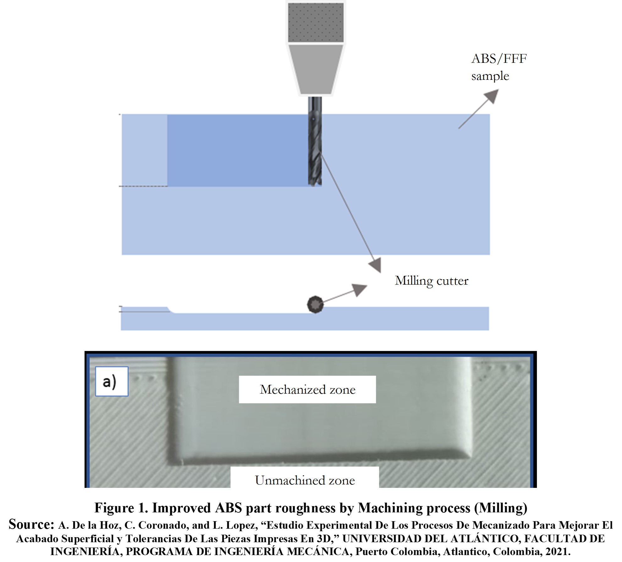
CP-02. The printed parts must be machined to improve the surface finish and tolerances (see Figure 1).
Machining achieves substantial improvements in part roughness and significant improvements in tolerances without reducing mechanical strength. However, the optimum results depend on the FFF process and machining parameters. It must be ensured that the part has sufficient perimeter layers to support machining [1], [6], [7], [8], [9], [10], [11], [12], [13].
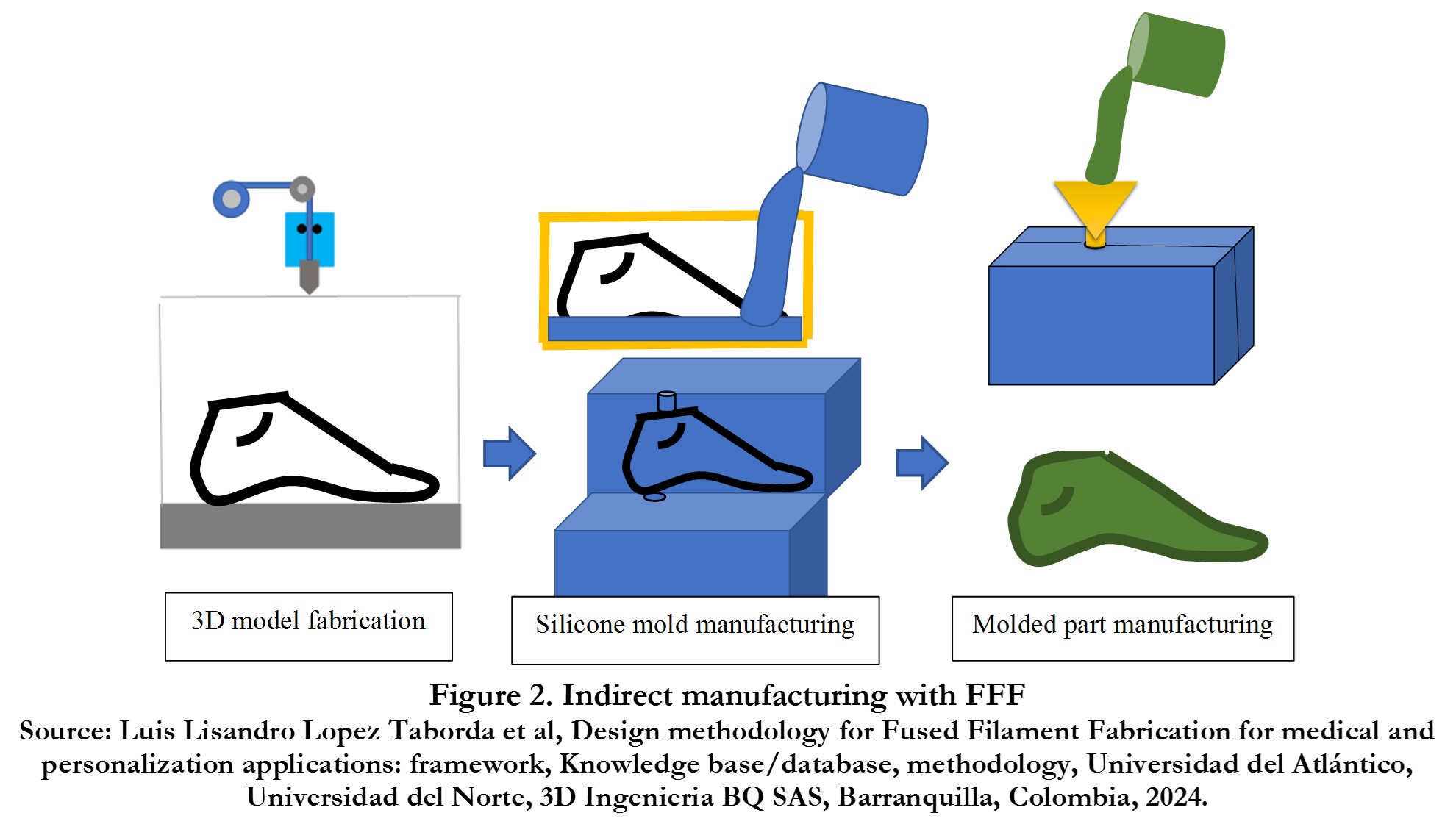
CP-08. Indirect manufacturing (example, molding with printed mold like Figure 2) should be used to expand the possibilities of FFF, both in terms of materials and processes, applications, and uses, while increasing strength, reducing manufacturing times and costs, reducing tolerances and fits, reducing roughness and reducing the weight of parts, among other competitive advantages [21], [22], [23], [24], [15], [25], [26], [27], [28], [29], [30], [31], [32], [33], [34].
For more guidelines using FFF process chain, go to the database.
Improvement in tolerances
During the case analysis, improvements in properties such as tolerances, roughness, mechanical strength, and times/costs were identified through the combination of FFF or FDM with conventional processes. Table 1 provides a partial overview of the results obtained specifically for the tolerances case
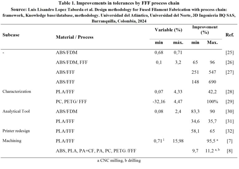

To interpret the findings in Table 1, an example is provided:
- The lowest Tolerances values associated with small percentages of dimensional tolerances are presented for tolerances characterization (0.07%), analytical tools (0.08%) and machining (0.71%) see these values below of the min variable header in the respective subcase. The tolerances improvement values are presented as ranges (min and max), because the specific values depend on the interaction of FFF processing factors and conventional manufacturing.
To use the figures in Table 1 or the process chain database, from which these figures are derived, when designing a product, one should:
a) To know in advance what properties or specifications the product being designed should have, and in that case, to determine which process combination achieves the desired properties.
b) On the other hand, in the case of redesigning parts manufactured with FFF, whose properties are not by the desired specifications, the same table indicates the percentages of improvement possible by combining FFF with other specific processes; in this case, the processes that achieve the required improvements for the application to be designed are identified.
c) Once the possible processes or processes have been identified, the process chain database must be consulted to consult how the processes and their parameters are combined with FFF and print parameters.
d) The same database also contains process costs and times and the health and environmental impacts of using additional materials. This information will allow making objective decisions about the properties and costs associated with combining other materials and processes.
e) any details to expand or clarify can be read directly in the coded bibliographic reference.
The handling for other properties, such as mechanical properties, assembly, and others, is similar.
References
[1] J. S. Chohan and R. Singh, “Pre and post processing techniques to improve surface characteristics of {FDM} parts: a state of art review and future applications,” Rapid Prototyp. J., vol. 23, no. 3, pp. 495–513, 2017.
[2] A. Boschetto and L. Bottini, “Roughness prediction in coupled operations of fused deposition modeling and barrel finishing,” J. Mater. Process. Technol., vol. 219, pp. 181–192, May 2015.
[3] A. Boschetto, L. Bottini, and F. Veniali, “Finishing of Fused Deposition Modeling parts by {CNC} machining,” Robot. Comput. Integr. Manuf., vol. 41, pp. 92–101, Oct. 2016.
[4] P. M. Pandey, N. V. Reddy, and S. G. Dhande, “Improvement of surface finish by staircase machining in fused deposition modeling,” J. Mater. Process. Technol., vol. 132, no. 1–3, pp. 323–331, 2003.
[5] A. Boschetto and L. Bottini, “Surface improvement of fused deposition modeling parts by barrel finishing,” Rapid Prototyp. J., vol. 21, no. 6, pp. 686–696, Oct. 2015.
[6] Z. Zhu, V. Dhokia, and S. T. Newman, “A novel decision-making logic for hybrid manufacture of prismatic components based on existing parts,” J. Intell. Manuf., vol. 28, no. 1, pp. 131–148, Sep. 2017.
[7] Z. Zhu, V. Dhokia, A. Nassehi, and S. T. Newman, “Investigation of part distortions as a result of hybrid manufacturing,” Robot. Comput. Integr. Manuf., vol. 37, pp. 23–32, Feb. 2016.
[8] A. De la Hoz, C. Coronado, and L. Lopez, “Estudio Experimental De Los Procesos De Mecanizado Para Mejorar El Acabado Superficial y Tolerancias De Las Piezas Impresas En 3D,” UNIVERSIDAD DEL ATLÁNTICO, FACULTAD DE INGENIERÍA, PROGRAMA DE INGENIERÍA MECÁNICA, Puerto Colombia, Atlantico, Colombia, 2021.
[9] D. A. Roberson, A. R. T. Perez, C. M. Shemelya, A. Rivera, E. MacDonald, and R. B. Wicker, “Comparison of stress concentrator fabrication for 3D printed polymeric izod impact test specimens,” Addit. Manuf., vol. 7, pp. 1–3, 2015.
[10] C. C. Ploch, C. S. S. A. Mansi, J. Jayamohan, and E. Kuhl, “Using 3D Printing to Create Personalized Brain Models for Neurosurgical Training and Preoperative Planning,” World Neurosurg., vol. 90, pp. 668–674, Jun. 2016.
[11] O. C. Burdall, E. Makin, M. Davenport, and N. Ade-Ajayi, “3D printing to simulate laparoscopic choledochal surgery,” J. Pediatr. Surg., vol. 51, no. 5, pp. 828–831, May 2016.
[12] Stratasys, “TECHNICAL APPLICATION GUIDE: Silicone Molding With FDM Patterns.” 2015.
[13] Y. He, G. Xue, and J. Fu, “Fabrication of low cost soft tissue prostheses with the desktop 3D printer,” Sci. Rep., vol. 4, no. 1, Nov. 2014.
[14] Stratasys, FDM for Composite Tooling. Stratasys, 2017.
[15] M. Chhabra and R. Singh, “Rapid casting solutions: a review,” Rapid Prototyp. J., vol. 17, no. 5, pp. 328–350, 2011.
[16] S. Singh and R. Singh, “Fused deposition modelling based rapid patterns for investment casting applications: a review,” Rapid Prototyp. J., vol. 22, no. 1, pp. 123–143, 2016.
[17] Stratasys, “APPLICATION GUIDE: Thermoforming.” 2015.
[18] M. HÉCTOR, A. ORTIZ, and L. LOPEZ, “DISEÑO Y CONSTRUCCIÓN DE PROTOTIPO DE MOLDE PARA RECONSTRUCCIÓN ÓSEA A PARTIR DE TOMOGRAFÍA COMPUTARIZADA MEDIANTE IMPRESIÓN 3D,” UNIVERSIDAD DEL ATLÁNTICO, FACULTAD DE INGENIERÍA, DEPARTAMENTO DE INGENIERÍA, PROGRAMA DE INGENIERÍA MECÁNICA, Puerto Colombia – Atlántico, COLOMBIA, 2021.
[19] L. Ruiz-Huerta, Y. C. Almanza-Arjona, A. Caballero-Ruiz, H. A. Castro-Espinosa, C. M. D\’\iaz-Aguirre, and E. E. y Pérez, “{CAD} and {AM}-fabricated moulds for fast cranio-maxillofacial implants manufacture,” Rapid Prototyp. J., vol. 22, no. 1, pp. 31–39, 2016.
[20] P. A. Thomas, P. K. Aahlada, N. S. Kiran, and J. Ivvala, “A Review On Transition In The Manufacturing Of Mechanical Components From Conventional Techniques To Rapid Casting Using Rapid Prototyping,” Mater. Today Proc., vol. 5, no. 5, pp. 11990–12002, 2018.
[21] O. Abdelaal, S. Darwish, K. A. Elmougoud, and S. Aldahash, “A new methodology for design and manufacturing of a customized silicone partial foot prosthesis using indirect additive manufacturing,” Int. J. Artif. Organs, vol. 42, no. 11, pp. 645–657, 2019.
[22] Stratasys, “TECHNICAL APPLICATION GUIDE FDM Tooling for Sheet Metal Forming: Hydroforming and Rubber Pad Press.” 2015.
[23] Stratasys, “TECHNICAL APPLICATION GUIDE: FDM FOR SAND CASTING.” 2013.
[24] Stratasys, “TECHNICAL APPLICATION GUIDE: Investment Casting with FDM Patterns.” 2015.
[25] J. Singh, R. Singh, and H. Singh, “Investigations for improving the surface finish of {FDM} based {ABS} replicas by chemical vapor smoothing process: a case study,” Assem. Autom., vol. 37, no. 1, pp. 13–21, Feb. 2017.
[26] L. M. Galantucci, I. Bodi, J. Kacani, and F. Lavecchia, “Analysis of Dimensional Performance for a 3D Open-source Printer Based on Fused Deposition Modeling Technique,” Procedia {CIRP}, vol. 28, pp. 82–87, 2015.
[27] M. Shahrain, T. Didier, G. K. Lim, and A. J. Qureshi, “Fast Deviation Simulation for `Fused Deposition Modeling’ Process,” Procedia {CIRP}, vol. 43, pp. 327–332, 2016.
[28] K. Tiwari and S. Kumar, “Analysis of the factors affecting the dimensional accuracy of 3D printed products,” Mater. Today Proc., vol. 5, no. 9, pp. 18674–18680, 2018.
[29] J. MARTÍNEZ, D. SEPÚLVEDA, and L. LOPEZ, “ESTUDIO EXPERIMENTAL PARA MEJORAR LA PRECISIÓN DIMENSIONAL Y SUPERFICIAL DE PIEZAS FABRICADAS MEDIANTE MODELADO POR DEPOSICIÓN FUNDIDA,” UNIVERSIDAD DEL ATLÁNTICO, FACULTAD DE INGENIERÍA, PROGRAMA DE INGENIERÍA MECÁNICA, Puerto Colombia, Atlantico, Colombia, 2021.
[30] A. Boschetto and L. Bottini, “Design for manufacturing of surfaces to improve accuracy in Fused Deposition Modeling,” Robot. Comput. Integr. Manuf., vol. 37, pp. 103–114, Feb. 2016.
[31] S. A. Tronvoll, C. W. Elverum, and T. Welo, “Dimensional accuracy of threads manufactured by fused deposition modeling,” Procedia Manuf., vol. 26, pp. 763–773, 2018.
[32] P. Minetola and M. Galati, “A challenge for enhancing the dimensional accuracy of a low-cost 3D printer by means of self-replicated parts,” Addit. Manuf., vol. 22, pp. 256–264, 2018.