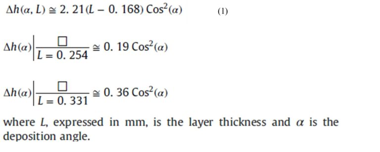
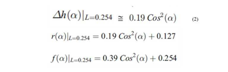
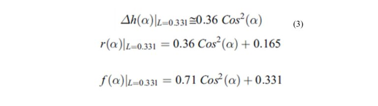
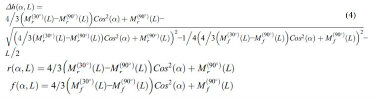
Mr and Mf are values of r-radius and f-spacing between filaments, measured at specific angles α indicated of 30° and 90°. Mr and Mf values were taken based on r and f measured in [3] and [4] at layer heights L of 0.254mm and 0.331mm, for FDM systems and ABS material.
References
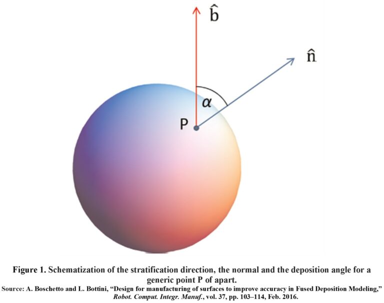
[1] A. Boschetto and L. Bottini, “Design for manufacturing of surfaces to improve accuracy in Fused Deposition Modeling,” Robot. Comput. Integr. Manuf., vol. 37, pp. 103–114, Feb. 2016.
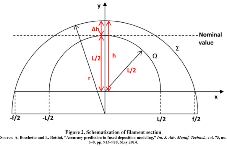
[2] A. Boschetto and L. Bottini, “Accuracy prediction in fused deposition modeling,” Int. J. Adv. Manuf. Technol., vol. 73, no. 5–8, pp. 913–928, May 2014.
[3] A. De la Hoz, C. Coronado, and L. Lopez, “Estudio Experimental De Los Procesos De Mecanizado Para Mejorar El Acabado Superficial y Tolerancias De Las Piezas Impresas En 3D,” UNIVERSIDAD DEL ATLÁNTICO, FACULTAD DE INGENIERÍA, PROGRAMA DE INGENIERÍA MECÁNICA, Puerto Colombia, Atlantico, Colombia, 2021.
[4] A. Boschetto, V. Giordano, and F. Veniali, “3D roughness profile model in fused deposition modelling,” Rapid Prototyp. J., vol. 19, no. 4, pp. 240–252, Jun. 2013.